
Measuring Prop Thrust
As a beginning electric flier, I became very interested in propeller thrust and the propeller equations suggested for predicting performance. My modeling is done in Idaho Falls, Idaho, at an elevation of more than 4,700 feet—predicting thrust of electric flight systems is important. I wanted accurate measurements of actual thrust with a particular system, and I wanted to know what thrust would be available if I changed the propeller or rpm.
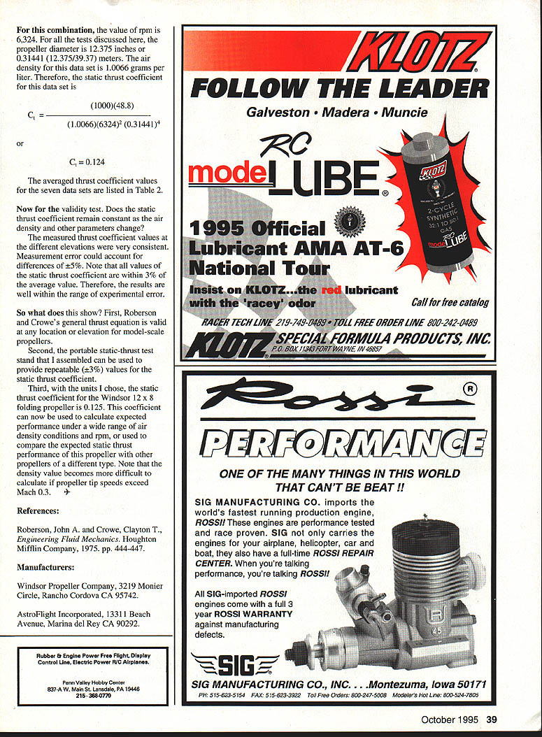
As a first step, I designed and built a portable thrust-test stand. With a portable test stand, I can measure propeller thrust anywhere.
The second step was testing the suggested thrust equations. To explain my own propeller thrust measurements, I tried applying equations found in modeling literature. None verified. Some of the suggested equations predicted results almost 30% different from the static thrust I measured with my equipment.
As a result, I decided to test a general thrust equation for full-scale propellers from an engineering text: Engineering Fluid Mechanics by John A. Roberson and Clayton T. Crowe.
My biggest concern was the "scale effect" of the propellers. Would shifting from propeller diameters measured in feet to diameters measured in inches cause the equation to fail?
The Roberson and Crowe equation differed from the other equations I had found—it included an air-density term. To test this equation I needed to vary and calculate the air density, measure rpm and static thrust, and calculate the static thrust coefficient. It's easy to change the air density if you have transportation—just change the test location to a different elevation.
I measured propeller thrust and rpm with my portable test stand at elevations ranging from approximately 1,400 feet to locations at more than 6,800 feet. Using the same drive system and propeller throughout the testing provided a series of measurements from different air-density conditions. I discovered that this equation really works!
The equation
Roberson and Crowe show the development of a general thrust equation for the thrust of a propeller:
F = C_t p n^2 D^4
In the units used here:
- Let f be the static thrust in ounces.
- Let p be the air density in grams per liter.
- Let n be the rpm.
- Let D be the propeller diameter in meters (inches / 39.37).
Changing the unit of force to ounces means F = 1000 f. Substituting and solving for the static thrust coefficient gives:
C_t = 1000 f / (p n^2 D^4)
Air density is calculated using:
p = 11.79 P / ([(T − 32) * (5/9)] + 273)
where:
- P is local station pressure in inches of mercury (in. Hg),
- T is temperature in degrees Fahrenheit (°F),
- p is in grams per liter.
Measurements and data processing
I collected seven sets of thrust measurements at five elevations to determine seven average values of the static thrust coefficient. Each data set consisted of measurements of thrust, rpm, motor voltage, and motor current.
At each location, measurements were made with as many battery combinations as possible. This produced a range of static-thrust and rpm values for each data set.
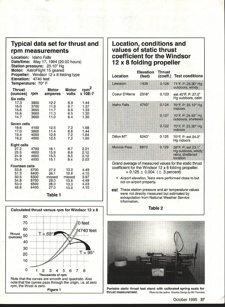
I plotted thrust versus rpm^2 for each data set. These plotted values should produce a straight line passing through the origin. The plotted points were averaged with a single straight data line through the origin. I then selected a convenient point on that line (a convenient number for thrust and rpm^2) for calculation. This procedure smoothed the data for each set and increased the reliability of each calculated static thrust coefficient.
For illustration, consider the Idaho Falls example data set. Convenient values for calculation are:
- rpm^2 = 4.0 × 10^7
- static thrust = 48.8 ounces
Typical data set for thrust and rpm measurements (Idaho Falls)
Location: Idaho Falls Date/time: May 17, 1994 (20:00 hours) Station pressure: 25.10" Hg Motor: AstroFlight 15 geared Propeller: Windsor 12 × 8 folding type Elevation: 4,740 feet Temperature: 70°F
Thrust (ounces) | rpm | Motor amperes | Motor volts | rpm^2 × 10^-7 --- | ---: | ---: | ---: | ---: Six cells 17.3 | 3800 | 12.2 | 6.9 | 1.44 16.0 | 3700 | 11.8 | 6.7 | 1.37 15.6 | 3650 | 11.7 | 6.6 | 1.33 15.6 | 3600 | 11.3 | 6.5 | 1.30 14.7 | 3600 | 11.0 | 6.4 | 1.30
Seven cells 19.6 | 4100 | 12.5 | 7.2 | 1.68 17.0 | 3800 | 11.4 | 6.6 | 1.44 19.4 | 4050 | 12.8 | 7.2 | 1.64 19.2 | 4000 | 12.5 | 7.2 | 1.60
Eight cells 27.2 | 4700 | 16.1 | 8.7 | 2.21 25.5 | 4600 | 15.8 | 8.6 | 2.12 24.9 | 4600 | 15.5 | 8.5 | 2.12 24.0 | 4500 | 15.1 | 8.4 | 2.03
Fourteen cells 53.8 | 6700 | 27.2 | 13.0 | 4.49 51.3 | 6500 | 26.1 | 12.8 | 4.10 50.5 | 6300 | missed | missed | 3.97 54.8 | 6700 | 29.0 | 13.6 | 4.49 53.0 | 6500 | 28.0 | 13.3 | 4.23 49.6 | 6400 | 27.0 | 13.0 | 4.10
(Table 1)
Location, conditions and values of static thrust coefficient for the Windsor 12 × 8 folding propeller
Location | Elevation (feet) | Thrust coefficient (C_t) | Test conditions --- | ---: | ---: | --- Lewiston | 1,438 | 0.128 | 71°F, P: 28.30" Hg outdoors, windy Coeur d'Alene | 2,318* | 0.123 | est 45°F, P: 27.5" Hg outdoors, calm Idaho Falls | 4,740* | 0.124 | 70°F, P: 25.10" Hg indoors (also Idaho Falls) | 4,740* | 0.127 | 70°F, P: 24.93" Hg outdoors, sheltered (also Idaho Falls) | 4,740* | 0.122 | 70°F, P: 25.30" Hg indoors Dillon, MT | 5,240* | 0.125 | 70°F, P: est 24.2" Hg indoors Monida Pass | 6,870 | 0.129 | 58°F, P: est 23.1" Hg outdoors, windy/rainy, sheltered location
Grand average of measured values for the static thrust coefficient for the Windsor 12 × 8 folding propeller:
- C_t = 0.125 ± 0.004 (±3 percent)
*Airport elevation. Tests were performed close to but not on airport property. est: station pressure and air temperature values were not directly measured but estimated by extrapolation from National Weather Service information.
(Table 2)
Example calculation
For the Idaho Falls example:
- rpm = 6,324
- propeller diameter D = 12.375 inches = 0.31441 meters (12.375 / 39.37)
- air density p = 1.0066 grams per liter
- thrust f = 48.8 ounces
Using:
C_t = 1000 f / (p n^2 D^4)
we get:
C_t = (1000 × 48.8) / (1.0066 × (6324)^2 × (0.31441)^4) = 0.124
The averaged thrust coefficient values for the seven data sets are listed in Table 2 (see above).
Validity and conclusions
Does the static thrust coefficient remain constant as air density and other parameters change? The measured thrust coefficient values at different elevations were very consistent. Measurement error could account for differences of about ±5%. Note that all values of the static thrust coefficient are within 3% of the average value; therefore, results are well within the range of experimental error.
Conclusions:
- Roberson and Crowe's general thrust equation is valid at any location or elevation for model-scale propellers.
- The portable static-thrust test stand assembled for this work can provide repeatable (±3%) values for the static thrust coefficient.
- With the units chosen here, the static thrust coefficient for the Windsor 12 × 8 folding propeller is C_t = 0.125. This coefficient can be used to calculate expected performance under a wide range of air-density conditions and rpm, or to compare expected static thrust performance with other propellers of different types.
Note: density calculation becomes more difficult if propeller tip speeds exceed Mach 0.3.
References
- Roberson, John A. and Crowe, Clayton T., Engineering Fluid Mechanics. Houghton Mifflin Company, 1975, pp. 444–447.
Manufacturers
- Windsor Propeller Company, 3219 Monier Circle, Rancho Cordova, CA 95742.
- AstroFlight Incorporated, 13311 Beach Avenue, Marina del Rey, CA 90292.
Transcribed from original scans by AI. Minor OCR errors may remain.

