
Mechanical Fast Fill
Dave McDonald
Here is a simple, effective fast-fill device that will work for a suction-feed fuel system, and with some very minor modifications, will work on a pressure system.
The lineage of the design is unknown. Bob Whitney provided me with a filler very similar to this, and further modifications have produced the version seen here. Many of these filler systems used a Glo-Bee clamp ring, and the top portion of a Cox .049 cylinder. This design is similar in appearance, but it is dimensionally different.
(These dimensions are what I used for a particular application; you may wish to change the dimensions to suit your particular needs. I am currently working on a slightly smaller design for a Scale Racing application.)
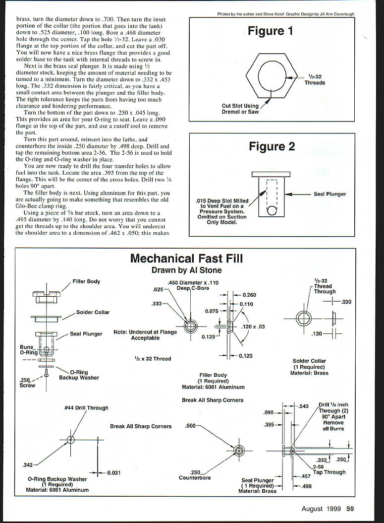
This filler may appear to be difficult to build; it is not. The first one is always more difficult than the second, third, etc. You should be able to build one of these in an hour or so. Simple machining is required to manufacture this design; this filler was made almost entirely using a small lathe. Only one part requires some mill work, and that may be accomplished using a drill press and mill vise.
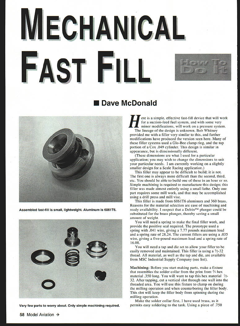
This filler is made from 6061-T6 aluminum and 360 brass. Reasons for the material selection are ease of machining and ready availability. I suspect that a Delrin™ plunger could be substituted for the brass plunger, thereby saving a small amount of weight.
You will need a spring to make the final filler work, and provide the positive seal required. The prototype used a spring with .041 in wire, giving a 7.77 lb maximum load and a spring rate of 28.24 lb/in. The current fillers are using a .035 in wire, giving a 5 lb maximum load and a spring rate of 16.08 lb/in.
You will need a tap and die set to allow your filler to be easily removed and maintained. This filler is using a 1/2-32 thread. All material, as well as the tap and dies, are available from MSC Industrial Supply Company (see Material list).
Machining
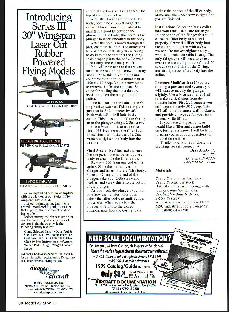
Before you start making parts, make a fixture that resembles the solder collar from the print from 3/4" hex material, 0.350 in long. You will want to tap this hex material 1/2-32. After tapping, cut a vertical slot through one wall into the threaded area. You will use this fixture to clamp on during the milling operation and when counterboring the filler body. This slot will keep the filler body from spinning during the milling operation.
Make the solder collar first. I have used brass, as it permits easy soldering to the tank. Using a piece of 0.750 in brass, turn the diameter down to 0.700 in. Then turn the inset portion of the collar (the portion that goes into the tank) down to 0.525 in diameter, 0.100 in long. Bore a 0.468 in diameter hole through the center. Tap the hole 1/2-32. Leave a 0.030 in flange at the top portion of the collar, and cut the part off. You will now have a nice brass flange that provides a good solder base to the tank with internal threads to screw in.
Next is the brass seal plunger. It is made using 1/2 in diameter stock, keeping the amount of material needing to be turned to a minimum. Turn the diameter down to 0.332 in for a length of 0.453 in. The 0.332 in dimension is fairly critical, as you have a small contact area between the plunger and the filler body. The tight tolerance keeps the parts from having too much clearance and hindering performance.
Turn the bottom of the part down to 0.250 in diameter by 0.045 in long. This provides an area for your O-ring to seat. Leave a 0.090 in flange at the top of the part, and use a cutoff tool to remove the part.
Turn this part around, reinsert into the lathe, and counterbore the inside 0.250 in diameter by 0.498 in deep. Drill and tap the remaining bottom area 2-56. The 2-56 is used to hold the O-ring and O-ring washer in place.
You are now ready to drill the four transfer holes to allow fuel into the tank. Locate the area 0.395 in from the top of the flange. This will be the center of the cross holes. Drill two 1/8 in holes 90° apart.
The filler body is next. Using aluminum for this part, you are actually going to make something that resembles the old Glo-Bee clamp ring.
Using a piece of 5/8 in bar stock, turn an area down to a 0.495 in diameter by 0.140 in long. Do not worry that you cannot get the threads up to the shoulder area. You will undercut the shoulder area to a dimension of 0.462 in x 0.050 in; this makes sure that the body will seal against the top of the solder collar.
After the threads are on the filler body, bore a hole 0.333 in through the center. This dimension is critical to maintain a good fit between the plunger and the body; this permits the plunger to work smoothly in the body.
After the hole is bored through the part, chamfer the hole. The dimension here is not critical; all you are trying to do is to make sure that the O-ring seals properly into the body. Leave a 0.120 in flange and cut the part off.
You will now use the fixture you made at the beginning; screw the body into it. Place this in your lathe and counterbore the top to a dimension of 0.450 in x 0.110 in deep. You are now ready to remove the fixture and part. Set aside for milling the slots that are used to tighten the body into the collar.
The last part on the lathe is the O-ring backup washer. This is simply a part that is 0.342 in diameter by 0.031 in thick with a #44 drill hole in the center. This is used to hold the O-ring on the plunger using a 2-56 screw.
Use a 1/8 in end mill to make two slots 0.075 in deep across the filler body. These slots permit the use of a Cox wrench to tighten the body into the solder collar.
Final Assembly
After making sure that the parts have no burrs, you are ready to assemble the filler valve.
Remove 0.100 in from one end of the spring. Slide the spring over the plunger and insert into the filler body. Place an O-ring on the end of the plunger, take your 2-56 screw and washer, and screw this into the bottom of the plunger.
As you work the plunger, you will note how the transfer holes open below the filler body, permitting fuel to transfer. When you allow the plunger to return to the closed position, note how the O-ring seals against the bottom of the filler body. Make sure the 2-56 screw is tight, and you are finished.
Installation
Solder the brass collar into your tank. Take care not to get solder on top of the flange; this could cause the filler body to not seal properly. Screw the filler body into the collar and tighten with a Cox wrench. Do not overtighten; all you want to do is make sure this is snug. The only things you will need to check over time are the tightness of the 2-56 screw, the condition of the O-ring, and the tightness of the body into the collar.
Pressure Modification
If you are running a pressure fuel system, you will want to modify the plunger slightly. Use a 1/8 in or smaller end mill to make vertical slots from the transfer holes (see Fig. 2). I suggest you mill approximately 0.015 in deep. This will still provide ample wall thickness and provide an avenue for your tank to vent while filling.
If you have any questions, or would like a filler and cannot build one, just let me know. I will be happy to assist you with questions, or in obtaining a filler.
Thanks to Al Stone for doing the drawings for this project.
Dave McDonald Box 384 Daleville, IN 47334 DMcD143@aol.com
Material
- 3/8 and 5/8 in aluminum bar stock
- 1/2 and 3/8 in brass bar stock
- 0.420 in OD compression spring, with 0.035 in dia. wire
- 1/4 x 3/16 in Buna N O-ring
- 2-56 x 1/4 in screw
All material may be obtained from MSC Industrial Supply Company; Tel.: (800) 645-7270.
Transcribed from original scans by AI. Minor OCR errors may remain.

