
Megas Aetos
Roger S. Greene
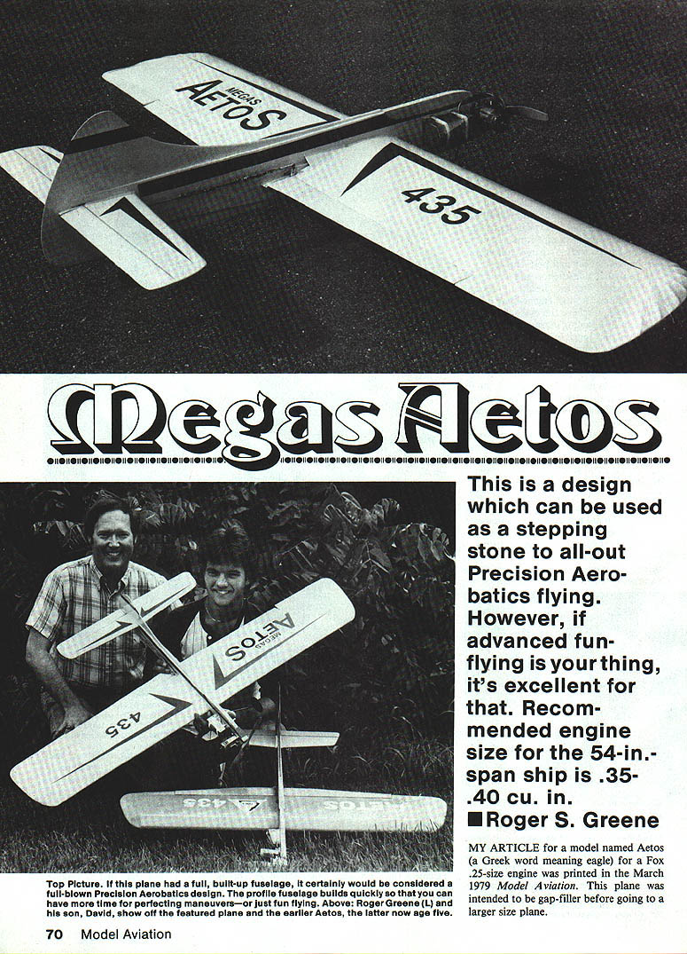
This is a design that can be used as a stepping stone to all-out precision aerobatics flying. However, if advanced fun-flying is your thing, it's excellent for that as well. The 54-in. span Megas Aetos is intended to fit a .35–.40 cu. in. engine and gives the novice the feel of a larger plane without too much expense.
Overview
- Name: Megas Aetos (Greek for "large eagle"). The original Aetos was a Fox .25-size design; this is an enlarged version.
- Wingspan: 54 in.
- Recommended engine: .35–.40 cu. in.
- Recommended tank capacity: approximately 3.75 fl. oz. (a 4-oz Sullivan tank may be used).
- Wing: 5.5:1 aspect ratio with an average of 20% flaps for very good turning ability.
- Controls: one-to-one ratio (same as used by many top stunt pilots for flaps and elevator).
- Landing gear: torsion bar setup for bounce-free takeoffs and landings.
- Notes: Stabilizer and elevator are large for smoother control through maneuvers; building the stabilizer and elevator as built-up surfaces can save about an ounce in tail weight.
Fuel Tank
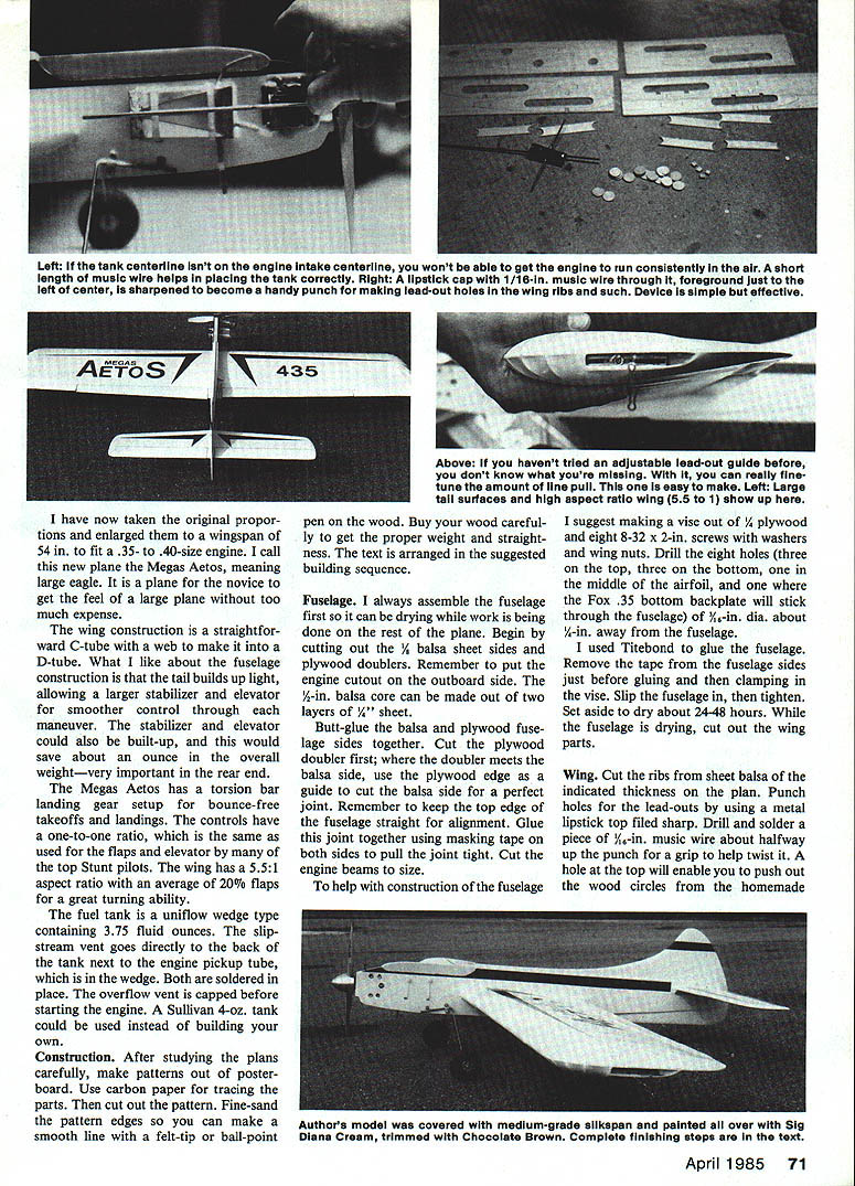
The fuel tank shown on the plans is a uniflow wedge type holding about 3.75 fl. oz. The slipstream vent goes directly to the back of the tank next to the engine pickup tube, which is in the wedge; both vents are soldered in place. The overflow vent is capped before starting the engine. A 4-oz. Sullivan tank may be used instead of building your own.
If you build the tank:
- Use 4 x 10-in. tin stock and 1/8-in. brass tubing.
- Use only one solder joint on the tank.
- A light-duty soldering gun can be used, but a heavy-duty gun will do a better job.
- Ensure the tank pickup aligns with the engine pickup (see Engine Installation).
Construction
After studying the plans carefully, make patterns out of posterboard. Use carbon paper for tracing the parts, then cut out and fine-sand the pattern edges so you can draw smooth lines on the wood with a felt-tip or ball-point pen. Buy wood carefully for proper weight and straightness.
The following sequence follows the suggested building order.
Fuselage
- Assemble the fuselage first so it can be drying while you work on other parts.
- Cut out the 1/8-in. balsa sheet sides and plywood doublers. Remember to put the engine cutout on the outboard side.
- The 1/2-in. balsa core can be made from two layers of 1/4-in. sheet.
- Butt-glue the balsa and plywood fuselage sides together. Cut the plywood doubler first; where the doubler meets the balsa side, use the plywood edge as a guide to cut the balsa side for a perfect joint. Keep the top edge of the fuselage straight for alignment.
- Glue the joint using masking tape on both sides to pull the joint tight. Cut the engine beams to size.
To help with fuselage clamping, make a simple vise:
- Materials: 1/4-in. plywood and eight 8-32 x 2-in. screws with washers and wing nuts.
- Drill eight holes in the vise base (three on top, three on bottom, one in the middle of the airfoil, and one where the Fox .35 backplate will stick through the fuselage). Make the holes 5/16-in. dia. about 1/2 in. away from the fuselage.
- Remove the tape from the fuselage sides just before gluing and then clamp in the vise.
- Set aside to dry about 24–48 hours.
I used Titebond for the fuselage glue.
Fuselage details (tail wheel, bulkhead, blocks)
After the fuselage has dried:
- Bend the tailwheel gear out of 1/16-in. music wire.
- Cut the bulkhead, bind with two wraps of copper wire around the notches, glue into the fuselage at the proper angle.
- Glue in both top and bottom 1/4-in. balsa blocks to the fuselage; pin and let dry.
Wing — Cutting ribs and preparing
- Cut ribs from sheet balsa of the thickness indicated on the plan. To avoid cracking, punch the lead-out holes before cutting the ribs out of the sheet.
- Punch holes for lead-outs using a metal lipstick-tube top filed sharp as a homemade punch. Drill and solder a piece of 1/16-in. music wire about halfway up the punched hole to provide a grip to help twist it out. A hole at the top will enable you to push out the wood circles from the punch.
- Fine-sand the ribs to the airfoil outline.
Wing — Building the panel
- Place a sheet of wax paper over the wing plan; splice the trailing edge sheeting over the plan.
- Glue the ribs in place on the trailing edge sheeting. Glue the two 1/4-in. square bellcrank supports at the same time the center five ribs are glued in place. Also glue in the bellcrank platform.
- Glue the top 1/4-in. square spar and top trailing edge planking at this time as well.
- While the wing is drying, start work on the solid surfaces: flaps, rudder, stabilizer, and elevator.
Solid surfaces — Stabilizer, elevator, flaps, rudder
- Stabilizer and elevator:
- Cut from 1/8-in. sheet balsa. If unavailable, 1/4-in. will do; 5/32-in. is preferred for strength.
- Draw a centerline on the edge side of each surface to use as a guide for sanding and hinging.
- Sand the leading edge of flaps and elevator to a wedge with about 30° on each side. Shape the airfoil per the plan, keeping the stabilizer leading edge blunt.
- Use a Sig wire-type control horn or make your own. I used three hinges per side on the flaps and two per side on the elevator. Glue the control horns with epoxy for strength. Epoxy the hinges into the stabilizer and elevator and the horn bearing to the stabilizer.
- Flaps:
- Cut and sand to the proper outline.
- Use a Sig offset horn; epoxy in place.
- Do not sand the flap tips where they are glued to the wing trailing edge.
- Do not glue the flaps or flap tips to the wing yet — wing and fuselage must be glued first.
- Rudder:
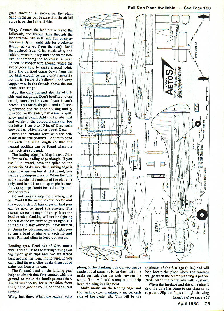
- Cut from 1/8-in. sheet with the grain direction as shown on the plan. Sand the airfoil curve so it is on the inboard side.
Wing again (bottom spar & leading edge)
- Remove pins, flip the wing over, pin the plan, and glue on the bottom spar (which is now on top) and the leading edge triangle. Let dry thoroughly.
Lead-outs, bellcrank and pushrod
- Connect the lead-out wires to the bellcrank and thread them through the inboard-side ribs (left side for counterclockwise flying, right side for clockwise flying as viewed from the rear).
- Bend the pushrod from 1/8-in. music wire. Solder a washer on top and one on the bottom, sandwiching the bellcrank. A wrap or two of copper wire where the solder goes helps make a good joint.
- Have the pushrod come down from the top high enough so the bellcrank arms do not hit it. Secure the bellcrank and wrap copper wire in the threads above the nut before soldering.
- Bend the lead-out wires with the bellcrank in neutral position. Be sure to bend the ends the same length so that the neutral position can be found when the pushrods are soldered.
Wing tips, adjustable lead-out guide, and tip weight
- Add wing tips and the adjustable lead-out guide. Materials for the guide:
- 3/64-in. plywood for the slide housing
- 1/4-in. plywood for the slider
- 4-40 x 1/2-in. screw and a T-nut
- Add tip ribs and weight the outboard wing tip. Recommended tip weight: 9–10 in. of 1/4-in. rosin-core solder (~1/4 oz).
Leading edge planking
- Glue planking first to the leading edge triangle. If using 3/16-in. wood, have the splice on the center rib.
- Ensure the planking edge is straight when you buy it — a warped edge builds in a warp.
- When glue is dry, moisten the outside of the planking only and bend it to the spar; pin carefully (use a sponge to "paint" on the water).
- Do not finish gluing until the water has evaporated and the wood is dry. Use a hair dryer or heat gun if needed. This pre-forming keeps the planking from fighting the structure.
- Unpin the planking and use a glue gun to run a bead of glue over each rib and spar. Pin and align to keep out warps.
- When the leading edge gluing is dry, add a web of scrap 1/16-in. balsa sheet with the grain vertical between the spars for strength and alignment.
Center planking and locating the fuselage
- Make marks on the leading and trailing edge planking 1/4 in. on each side of the center rib — this gives the fuselage thickness (1/2 in.) and locates where the fuselage will go when center planking is put on.
- Plank the center ribs with 1/16-in. sheet.
Landing gear
- Bend the landing gear from 1/16-in. music wire.
- Bolt it to the fuselage using two Sig nylon gear clips and two tin straps bent around the 1/16-in. music wire. If you can't find the gear clips, make them from strips cut from a tin can.
- The forward bend in the gear helps absorb initial ground contact for smoother landings. Aim for a smooth transition from glide to ground roll.
Assembly — Joining wing and fuselage
- When fuselage and wing glue are dry, slip the spars through the wing slot first, then the wing into the fuselage.
- Use a triangle to square wing and fuselage: the angle should be 90° at the wing leading edge. The fuselage should be at 90° to the workbench (elevate the wing tips equally). Have the fuselage touching the workbench.
- Epoxy the wing to the fuselage.
- When dry, drill a 1/4-in. hole into the fuselage from the bottom through the wing near the leading edge (as shown on the plan) and glue in a dowel to help keep the assembly secure over the years.
Flaps
- Epoxy three hinges on the inboard flap first, then three hinges on the outboard wing trailing edge.
- When dry, epoxy the other end of the hinges into the flap and wing. Start at the center and work toward each tip. Do all second-stage hinge epoxying at one time, pushing each hinge in as far as it will go and leaving only a very small gap.
- Epoxy the horn bearing to the trailing edge of the wing.
Tail surfaces
- Epoxy the stabilizer and elevator into the fuselage, making sure the unit is perfectly aligned.
- Eyeball the stabilizer from the front so the bottom of the stabilizer appears to "sit" on the top of the wing.
- Measure the distance from the stabilizer tip hinge straight forward to the flap hinge; these distances should be the same on each side to avoid yaw when controls are applied.
- Reinforce the stabilizer mounting with 1/4-in. triangle scrap under each side of the fuselage.
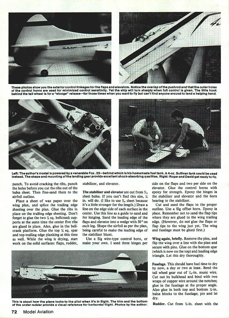
- Glue the rudder in place, including the lower portion (the lower portion provides a straight line reference during maneuvers).
Controls
- Start the hookup with the bellcrank and stabilizer in neutral. The stabilizer and bellcrank pushrod overlap 1–2 in.
- Wrap the overlap with copper wire in several small wraps spaced about 1/4 in. apart, then solder. Many small wraps are stronger than one long wrap.
- Solder the flap pushrod to the control surfaces the same way.
- I use a one-to-one hookup on the control surfaces; the airplane responds very quickly. The pushrods should go to the holes farthest from the control surface pivot point on the bellcrank. This setup makes the control response very fast. Adjust as you prefer.
Fuel tank (installation & alignment)
- If you use a purchased tank (3-1/2 to 4 oz. Sullivan slant tank or similar), ensure the center of the tank is on the centerline of the engine as viewed from the outboard tip.
- To check alignment: remove the glow plug and place a 1/16-in. music wire across the cooling fins toward the leading edge of the wing and over the tank; the tank pickup should be on this centerline.
- Locate the tank pickup correctly in relation to the engine pickup for consistent running.
Engine installation
- The cowling shown on the plans will fit most .35-size engines. A Fox .35 was used on the prototype.
- Location of the tank and pickup is crucial to consistent engine operation.
Finish
- Fine-sand the model with 400-grit sandpaper on a 2½ x 4 in. block for an even surface.
- Brush on three coats of clear dope; sand with 400-grit until smooth.
- Cover the wings with medium-grade silkspan. Brush on another three coats of clear over the silkspan and lightly sand with 400-grit wet-or-dry to smooth rough spots.
- Brush on one coat of sanding sealer over the entire plane. A homemade sealer: about eight tablespoons talcum powder per quart of clear (thin as needed). If using a light base color, add a small amount of that color to the sealer to help coverage.
- Sand the sealer with 400-grit. If wood grain still shows, apply another coat of sealer. When grain is covered, apply a coat of clear over the sealer.
- Apply base color (example: Sig Diana Cream) and trim (example: Chocolate Brown for letters and numbers). When color is dry, dilute clear at least 50% with thinner and brush one coat with a 1-in. or wider brush (single-stroke technique—do not brush repeatedly in one spot).
- Wait 24–48 hours between coats of color and clear, and a similar period before filling the tank so thinners can fully dry.
Flying
- The Megas Aetos flies smoothly and can perform the AMA Stunt pattern. It provides a good platform for learners progressing into aerobatics.
- Control surface deflection is limited to a maximum of 30° either side of neutral to reduce the possibility of over-control.
- The model is very stable because the stabilizer area is much larger than the elevator area, yet it will turn very sharply with full control input.
- Prototype weight: 42 oz. You can reduce weight by using iron-on covering and lighter wood.
Happy flying.
Transcribed from original scans by AI. Minor OCR errors may remain.

