
Messerschmitt — Bf110
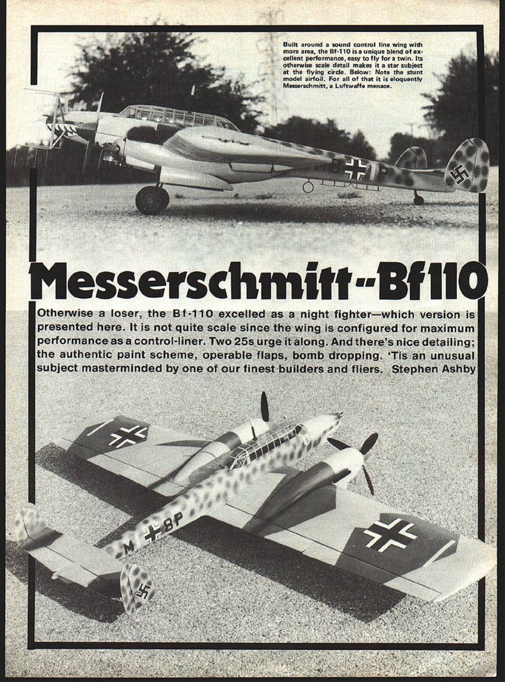
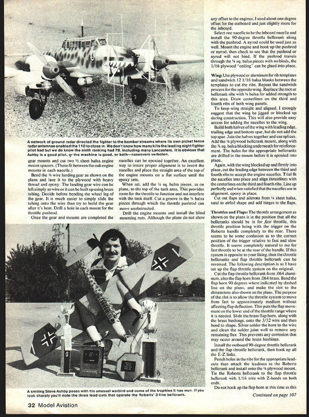
Otherwise a loser, the Bf 110 excelled as a night fighter — which version is presented here. It is not quite scale since the wing is configured for maximum performance as a control-line model. Two O.S. 25s urge it along. There's nice detailing: the authentic paint scheme, operable flaps, bomb dropping. 'Tis an unusual subject masterminded by one of our finest builders and fliers. — Stephen Ashby
Background
Billed by heavy prewar propaganda, the Bf 110 was to be the Luftwaffe's ultimate heavy-bomber escort and strategic fighter. With its long-range capabilities it would accompany its big brothers deep into enemy territory and at the same time the "Zerstörer" would wipe out all opposition along the way.
In early action with the invasion of Poland in 1939, the 110 was perhaps a mild success, considering it was fighting obsolete but highly maneuverable, high-winged PZLs. With all the 110's firepower — four 7.9-mm MGs and two 20-mm cannon located in the nose — its only advantage over the PZLs was a head-on attack. Even though the old PZLs could out-maneuver the 110, the small Polish Air Force was quickly defeated by sheer numbers.
During the Battle of France the 110 became even more vulnerable when more formidable Allied opposition learned to cope with its tactics. German pilots were forming offensive circles to protect one another from rear attacks, although this did nothing to prevent Allied attacks from either side.
Then came the Battle of Britain and the complete demise of the 110 as a long-range strategic fighter. It was simply no match for the British Spitfires and Hurricanes. Many were lost due to lack of maneuverability, rear protection and speed. To prevent further losses, Bf 109s were assigned as escort for the 110s. Even then the 109s didn't have the range the 110s had, thus leaving the 110s unprotected when the 109s returned for fuel.
Although the 110 was a failure in the Battle of Britain, it began to show promise elsewhere. Due to nocturnal RAF raids into Germany, a night-fighter force was hastily formed by the Luftwaffe. This early fighter force comprised Me 110-Cs, Ju 88s, and Me 109s, with the 110 proving to be the best suited aircraft for the task. In fact the first RAF bomber shot down at night over Germany was by a Me 110-C.
Because night interception tactics and equipment were primitive, intercepting the enemy was initially done solely by visual means and was at the mercy of the weather. To overcome these inefficiencies a network of ground radar stations was developed to guide a 110 to enemy bomber streams; the 110s could then use their own radar sets to make actual contact with the bombers.
The RAF countered this tactic with what became known as "Window" — thousands of small strips of aluminum dropped into the bomber slipstream producing false images on German radar screens. The Germans responded by developing new radar sets operating at higher frequencies that Window could not affect.
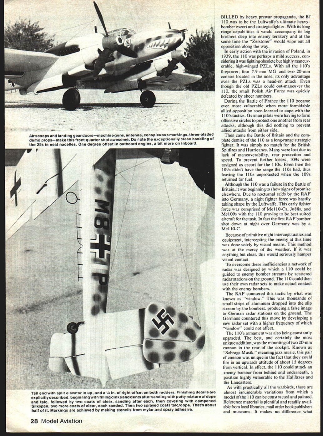
The 110's armament was also constantly upgraded. The best and most unique addition was the mounting of two 20-mm cannon in the rear of the cockpit. Known as Schräge Musik (literally "slanted music"), this pair of cannon could fire in an upwards attitude of about 15 degrees from the vertical. In effect, the 110 could attack an enemy bomber from behind and underneath, a position highly vulnerable to Halifaxes and Lancasters.
As with practically all warbirds, there are almost innumerable variations from which a model of the 110 can be constructed and painted. Reference material is plentiful and readily available from libraries, mail-order book publishers and museums. Whatever version or color scheme is chosen, the model will be an eye-catcher and a crowd pleaser.
Model Construction
Obviously the model isn't precision scale, primarily because the wing was built before the decision was made to turn the 110 into a control-line model. The 110 wing was constructed solely for the purpose of testing several ideas and designs. No minute spent building the model will be wasted the first time you hear both engines running, throttling down, landings, takeoffs and touch-and-gos.
Preliminary Construction
Construction is straightforward and presents no unusual problems — contrary to the fact that twins are usually more difficult to build. Study the plans carefully and become familiar with all the parts. Centerlines used during construction make this project considerably easier. Mark centerlines on all pieces requiring alignment.
Engine nacelles
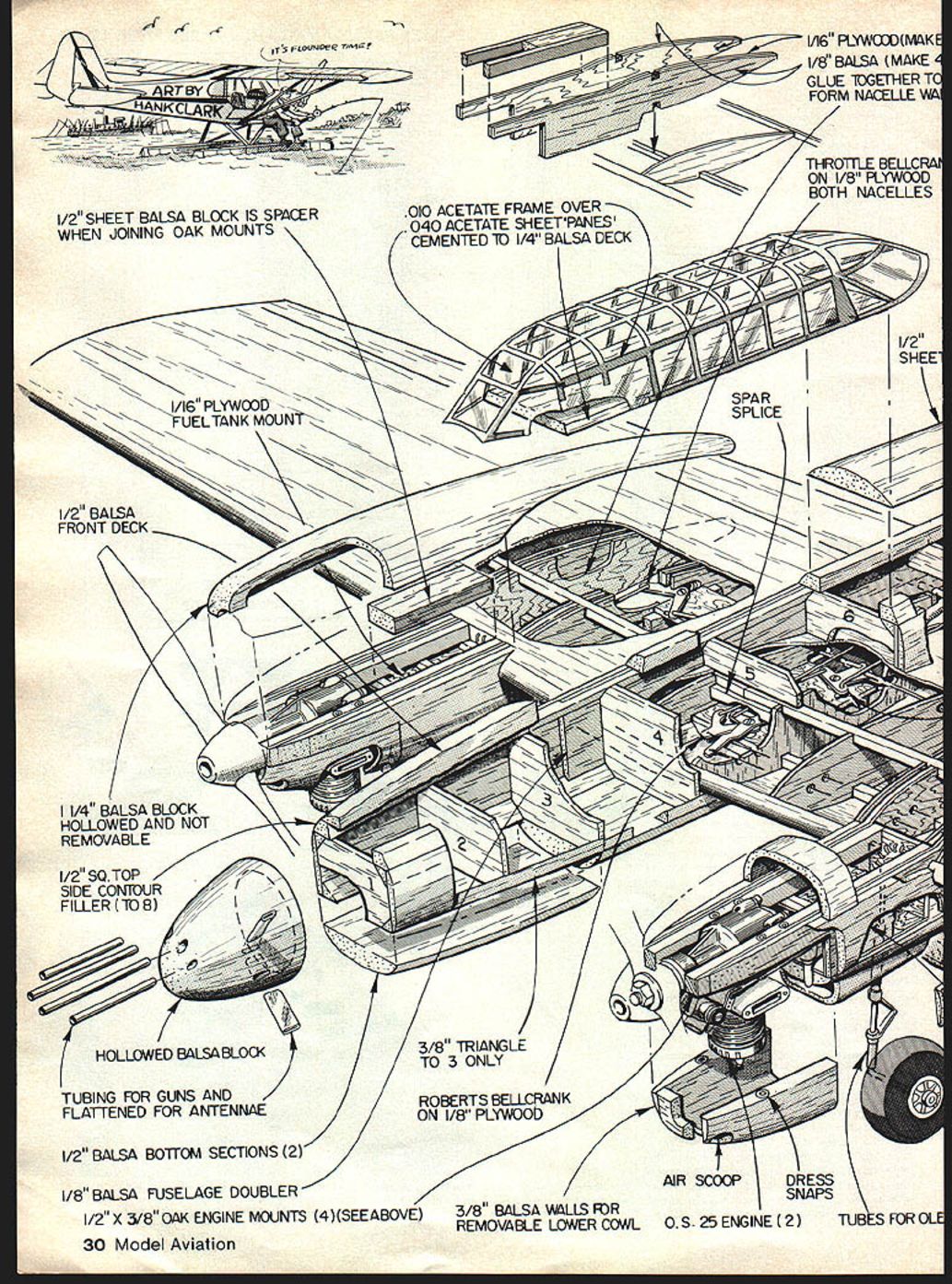
Use the nacelle side template from the plans to cut four 1/8" balsa sides and four 1/16" plywood nacelle sides. Use an aliphatic resin-type glue, such as Titebond, to adhere the plywood to the balsa sides. Mark thrust lines on the outside and inside of both nacelles; these will be needed when the nacelles are mounted into the wing.
Parts and materials (selected)
- 1/16" plywood (make 4)
- 1/8" balsa (make 4) — glue together to form nacelle wall
- 1/2" sheet balsa engine mount spacers (make 2)
- 1/2" x 3/8" oak engine mounts (4)
- 1/2" balsa front deck
- 1 1/4" balsa block (hollowed and not removable)
- 1/2" sq. top-side contour filler (7 to 8)
- Hollowed balsa block for tanks
- 1/2" balsa bottom sections (2)
- 1/8" balsa fuselage doubler
- 3/8" balsa walls for removable lower cowl
- 1/16" plywood fuel tank mount
- 1/8" plywood throttle bellcrank mounts (both nacelles)
- Throttle bellcrank on 1/8" plywood
- Spar splice
- Tubing for guns and flattened for antennae
- 1/4" balsa nacelle thickener
- Foam block clad in 1/16" sheet balsa
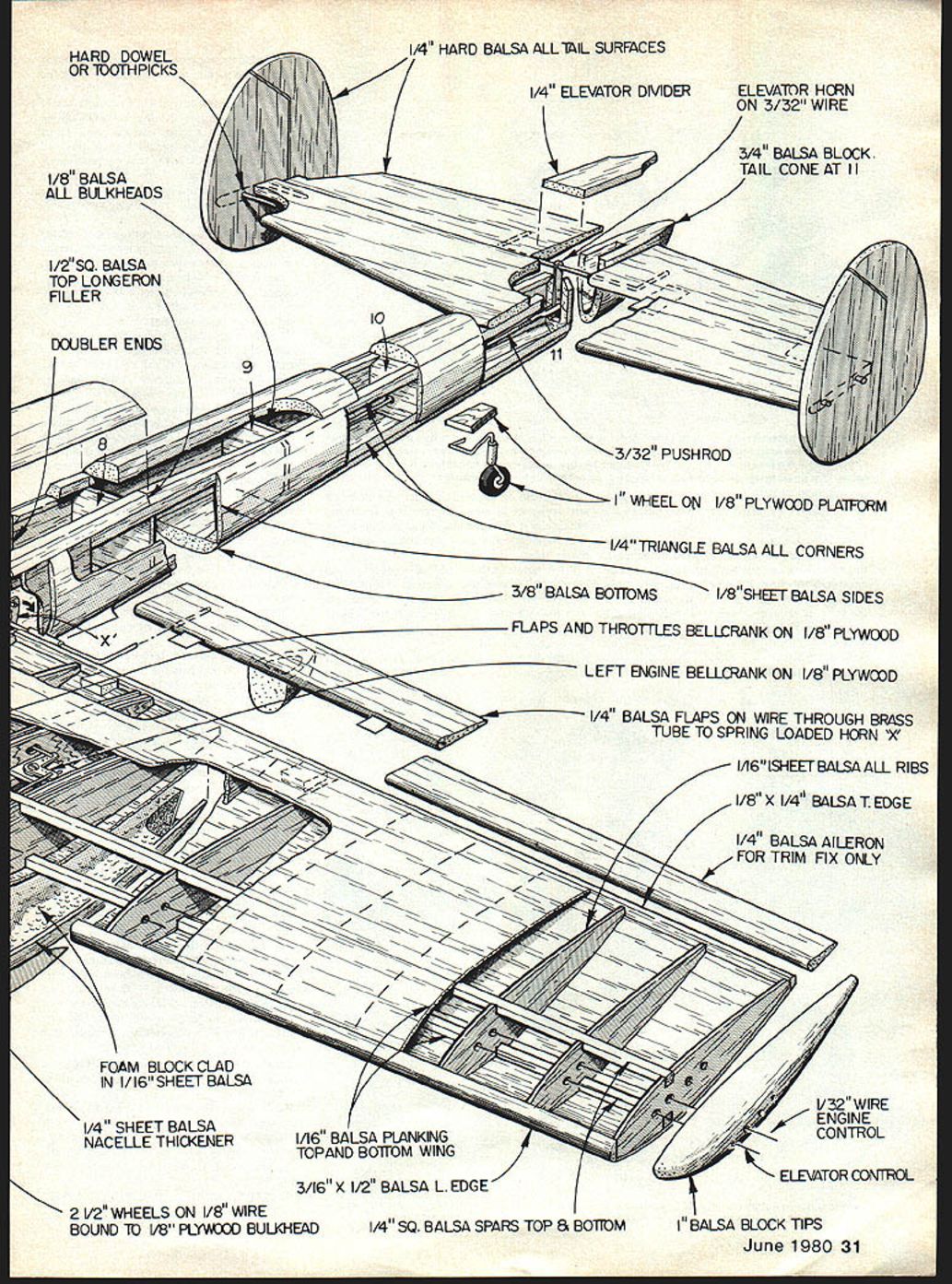
- 1/4" sheet balsa all tail surfaces
- 3/32" pushrod
- Elevator horn on 3/32" wire
- 1" wheel on 1/8" plywood platform
- 1/4" triangle balsa all corners
- 1/8" sheet balsa sides
- Flaps and throttles bellcrank on 1/8" plywood
- 1/4" balsa flaps on wire through brass tube to spring-loaded horn
- 1/16" sheet balsa all ribs
- 1/8" x 1/4" balsa trailing edge
- 1/4" balsa aileron for trim fix only
- 1/32" wire engine control
- 1/4" sq. balsa spars top & bottom
- 2 1/2" wheels on 1/8" wire bound to 1/8" plywood bulkhead
- O.S. 25 engine (2)
- Tubes for oil (hard dowel or toothpicks)
- Dress snaps for cowl fasteners
Make the gear mounts and cut two 1/2" sheet balsa engine mount spacers to fit between the oak engine mounts in each nacelle.
Bend the 1/4" wire landing gear as shown on the plans and lace it to the plywood with heavy thread and epoxy. The landing-gear wire can be left as simple wire or it can be built up using brass tubing. Decide before bending the wheel leg of the gear — it is much easier to slide the tubing onto the wire than to try to build the gear after it's bent. Drill a hole in each mount for the throttle pushrod.
Once the gear and mounts are completed the nacelles can be epoxied together. To ensure proper alignment, invert the nacelles and place the straight area at the top of the engine mounts on a flat surface until the epoxy sets.
When set, add the 1/4" square balsa pieces (as on plans) to the top of the tank area. This provides room for the throttle to function without interfering with the tank. Cut a groove in the 1/4" balsa pieces through which the throttle pushrod can move unobstructed.
Drill the engine mounts and install the blind mounting nuts. Although the plans do not show any offset to the engines, the author used about one degree offset for the outboard engine and slightly more for the inboard.
Select one nacelle to be the inboard nacelle and install the 90-degree throttle bellcrank along with the pushrod. Any rod could be used just as well. Mount the engine and hook up the pushrod or nyrod, then check to ensure the pushrod will not bind. If the pushrod travels through the 1/4" square balsa pieces with no binds, the 1/16" plywood "ceiling" can be glued into place.
Carve the flap fairing from a block of balsa and tack-glue it to the bottom of the flap. When satisfied with the shape of both nacelles, remove the top and bottom blocks, hollow out each one of these, then reglue permanently.
The landing doors are made by thoroughly soaking a piece of 1/8" balsa (large enough to make both doors of one nacelle). Wrap the soaked wood around the nacelle using wide masking tape to hold in place. With a hair dryer or heat gun, carefully dry the wood. When dry, split apart to make two doors and apply two coats of resin along with the braces shown on the plans. Repeat the process to make the second set of doors.
Engine exhaust stacks are 3/16" "Plastrut" plastic tubing. To bend the tubing, heat and place it into a simple jig: wrap sandpaper around a piece of the plastic tubing and sand a groove in a small block of balsa to a 90-degree angle. Heat the tubing by rolling it with your fingers about 6" above a candle flame. When the tubing becomes limp, quickly place the heated portion into the jig. With a little practice you should end up with 24 identical bent stacks.
Drill the 1/16" plywood stack plates for the exhaust, then epoxy them to the nacelle sides. Using the exhaust plates as guides, hand-drill into the balsa sides and glue the stacks into position with a cyanoacrylate adhesive (Hot Stuff). The stacks on the wing-tip side of the nacelles point upward, while the stacks on the fuselage side point downward.
The air scoops are built from 1/16" sheet balsa. Place ordinary window screen in these to simulate the grill. A resin finish gives strength as well as fuel proofing.
Wing
Use plywood or aluminum for rib templates and sandwich 12 1/16" balsa blanks between the templates to cut the ribs. Repeat for the opposite wing. Replace the root or bellcrank ribs with 1/8" balsa for added strength in this area. Draw centerlines on the third and fourth ribs of both wing panels.
To keep the wing straight and aligned, jig or block the wing during construction. This also provides easy access for adding the nacelles to the wing.
Build both halves of the wing with leading edge, trailing edge and bottom spar, but do not add the top spar. Join the halves together using splices. Add the 1/8" plywood bellcrank mount along with 1/4" square balsa blocking underneath for reinforcement. Drill holes for the appropriate bellcranks in the mount before epoxying it into place.
With the wing blocked up and firmly in place, cut the leading edge between the third and fourth ribs to accept the engine nacelles. Trial-fit the nacelles and align thrust lines with the centerlines on the third and fourth ribs. When satisfied with the alignment, epoxy the nacelles in place.
Cut out flaps and ailerons from 1/4" sheet balsa, sand to airfoil shape and add hinges to the flaps. Before planking the wing, check for trueness and accuracy. Plank the top of the wing with 1/16" balsa, then turn the wing over and plank the bottom. Cut holes for the elevator and flap pushrods. Mount the flap horn with epoxy and cloth to secure the brass bushings of the flap horn to the wing.
The wing-mounted radiators, underneath the wing, are made from 1/8" sheet balsa. Add window screen in these scoops for the grill effect and finish with resin.
Throttles and flaps
The throttle arrangement as shown on the plans places all the bellcranks for fast throttle with the trigger on the Roberts handle completely to the rear. If this orientation is opposite to your liking, the throttle bellcranks and the flap throttle bellcrank can be reversed. The following description follows the author's original setup.
Cut the flap throttle bellcrank from .064" aluminum and the flap horn from .064" brass. Bend the flap horn 90 degrees where indicated on the plans and make the slot to the dimensions shown. The purpose of the slot is to allow the throttle system to move from fast to approximately medium without affecting flap deflection. This places flap movement at the lower end of the throttle range where it is needed.
Slide the brass flap horn, along with the brass bushings, onto the 3/32" wire and then bend it to shape. Silver-solder the horn to the wire and clean the solder joint well to remove any remaining flux; this prevents corrosion around the brass bushings.
Install the outboard 90-degree throttle bellcrank and the flap throttle bellcrank, then hook up all the E-Z links. Punch holes in the ribs for the appropriate leadouts, attach the leadouts to the Roberts bellcrank and install onto the 1/8" plywood mount. Tie the Roberts bellcrank to the flap throttle bellcrank with 1/16" wire with Z-bends on both ends.
Do not hook up the flap horn at this time, as it will be connected after the fuselage has been added to the wing; however, check that there are no binds anywhere in the throttle system so that it works smoothly. If the bomb system is desired, mount the bomb-release bellcrank with its leadout at this time.
Springs for the bomb-release bellcrank and flap return can be purchased at a hardware store or made easily:
- Drill a small hole (1/16" dia. or preferably smaller) in a 3/16" dia. piece of brass tubing about 4" in length.
- Bend a 90-degree angle of about 1/2" in length on a piece of 36" .015" dia. music wire.
- Chuck the brass tubing into a variable-speed drill and insert the 1/2" bend of the wire into the hole in the tubing.
- Slowly turn the tubing with the drill until all the wire is wound around the tubing.
Note: The spring will flip back in reverse direction when released — use care and keep fingers clear.
Add the top spar (don’t forget to use splices) and glue the flap hinge reinforcements into place. Mount the flap horn stop and spring hardwood blocks inside the fuselage sides. Using the wing centerline on the fuselage side, set the flaps at neutral, epoxy the horn-stop block in place, and hook up the spring and pushrod to the flap horn. Adjust the spring so the flaps return to neutral easily. The flaps should deflect about 18 degrees.
Fuselage
Saw out both 1/8" balsa fuselage sides, 1/16" balsa doublers and all bulkheads per the plans. Draw fuselage centerlines on the outside of the balsa sides and the wing centerline in the wing-saddle area. Draw centerlines on the bulkheads. Drill holes in the bulkheads for the elevator pushrod.
Use Titebond to adhere the 1/8" balsa doublers to the 1/8" balsa sides. Glue all 1/4" triangular strips to the top inside edges of the balsa sides, except the 1/4" triangular strips from F3 rearward to the wing saddle.
Begin fuselage construction by gluing F3, F4, F5 and F6 into place using the top-view centerline for alignment. When dry, add F7 through F11. When thoroughly dry, glue the remaining bulkheads F1 and F2 in place.
If the balsa sides are difficult to bend around the nose bulkheads, use a damp sponge and lightly wet the outside of the fuse sides from F3 forward. This will cause the outside balsa to expand and produce a natural bend. After this, add the 1/4" triangular strips from F1 to F3 and glue the 1/4" triangular strips to the bottom inside of the fuselage.
Glue the 1/8" square strips onto the tops of the fuselage sides. Note that the 1/8" sq. balsa starts tapering at F6 rearward to F9. Epoxy the 3/32" plywood tailwheel mount to the bottom of the fuselage where indicated on the plans. Cut all 1/8" sheet balsa blocks for the top and bottom and tack-glue into place. Tack-glue the balsa nose block onto the fuselage nose. Add the 1/8" balsa strips on top of the fuselage sides in the canopy area.
Trace fuselage cross sections onto cardboard or posterboard and use these as guides for shaping the fuselage. Line up centerlines on the templates with the centerlines on the fuselage sides. Carve slowly and check frequently; finish by rough sanding.
Pop loose the nose, tail blocks, and all the 1/4" top and bottom blocks and hollow them.
Tail surfaces
All tail pieces are 1/4" sheet balsa. Airfoil both fins and rudders along with the stab and elevators. Epoxy the fins to the stab using round toothpicks as shown on the plans: drill starter holes for each toothpick, fill the holes with Titebond, then insert the toothpicks and let the glue surround them.
Epoxy the elevator control horn into the elevators along with the hinges. The stab sits on top of the fuselage sides so alignment is straightforward. Tack-glue the tail block into place plus the 1/4" piece of sheet balsa on top of the tail block. The top of the control horn may need to be ground down for clearance of movement — but do not remove too much so as to weaken the horn.
Details
Consider optional details now — it is simpler to add or plan for them before final finishing. Guns are fabricated from aluminum tubing and Hot Stuff glue. Drill small holes in the barrels to simulate cooling.
The radio gear under the fuselage is constructed with brass tubing and wire. Bend 1/16" wire around a broom handle to make the circular antenna and permanently epoxy it in place as indicated on the plans. The two bottom rear antennae are made per the plans. Crimp the 3/32" tubing of the antenna slightly to give a tight fit into the 3/32" tubing while still allowing it to be slipped in and out for transport.
In building the radar gear on the nose, make sure all joints are strongly soldered, preferably silver soldered. These parts can be dangerous to any spectator if they come apart or fall off.
Build the canopy by first carving a balsa block to shape and applying a finish (preferably resin). Draw a heated sheet of .040" acetate down over the mold. The frame of the canopy is formed the same way: with the .040" canopy still on the mold, draw a .010" acetate sheet over the formed canopy. With a sharp knife, cut out the canopy frame. Use Hot Stuff to adhere the frame to the canopy, taking extreme care with the adhesive. Before the canopy is permanently glued into position, complete the removable antenna mount: sandwich a small 2-56 nut between two pieces of 3/32" plywood, leaving slightly more than 5/8" of threads protruding. Cut a hole in the canopy just large enough for the nut; sand the nut between the plywood pieces so it nests flush. This removable antenna helps during transport.
Add the radio operator's gun, pilot and navigator figure, check fit, then glue the canopy to the fuselage.
Finish
The finish on the original was achieved by the talc-and-dope method. If you are unfamiliar with this method, use whichever finishing method you prefer. If you want to try talc and dope, follow this guide:
- Sand the balsa smooth with #320 sandpaper and fill all dings with a putty of dope and talcum powder, mixed to a syrupy consistency.
- Spray or brush on two coats of clear dope to bare wood, sanding between coats with #320.
- Apply Silkspan (SGM medium) to all surfaces with the Silkspan lightly dampened.
- Apply two more coats of clear dope and sand lightly between coats.
- Brush or spray on a mixture of dope and talcum powder thinned just enough to spray; add a little color dope (preferably white) to make flaws more visible.
- Sand with #320 to remove most of the talc; apply two more coats of filler and sand with #400 between coats.
- When satisfied, add a coat of 50% thinned dope, then wet-sand with #400.
- Fuel-proof the engine compartments and epoxy the dress-snap-on cowl fasteners into place before color coats.
Aeroglaze dope was used throughout on the original, with colors mostly mixed from Military Flats. Use stencils cut from drafting mylar and spray adhesive for markings; cover marking areas until the overall color is applied. Mask the shark's mouth with masking tape or liquid mask.
Suggested colors and mixes:
- Top surfaces — Light Gray: Storm Gray.
- Dark Gray — 1 part Storm Gray to 1 part Flat Black.
- White — Flat White.
- Yellow — 1 part Flat Cub Yellow to 1 part Flat White with a touch of Stearman Red.
- Red — Stearman Red with a touch of flat to flatten the finish.
- Black — Flat Black.
- Bottom surfaces — Light Blue: 1 part Navy Blue to 16 parts Flat White.
The back cover of Wings magazine (June 1972) was used as a guide for colors and camouflage.
Flying
Pick a calm day for your initial flight. The 110 will handle wind, but eliminating variables is wise.
Balance the model with the CG marked on the plans; use this as a guide to your preference. The original needed no nose or tail weight, but your build may differ.
Use the ailerons and rudders for trim. The author used a rudder offset of about 1/4° to keep the airplane taut on the lines at low throttle. Lightly glue the ailerons at neutral; they can be adjusted in the field.
Until you are well acquainted with the model's flying characteristics, avoid slow landings and takeoffs directly into the wind. Instead, perform these somewhat perpendicular to the wind. With deflected flaps and heading into the wind the model will balloon due to excessive lift, creating loose line tension.
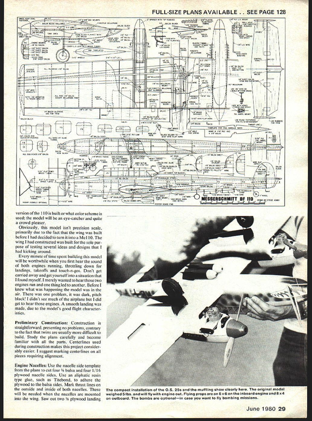
The O.S. 25s pull the 110 with no problem. The best prop arrangement seemed to be an 8x6 for the inboard engines and an 8x4 for the outboard. The original weighed just over 5 lbs and would fly on either engine (not recommended as a practice, but reassuring if one engine quits in flight).
Very realistic takeoffs, taxi, touch-and-gos and landings can be achieved, as well as bombing missions. If you have half the fun the author had with this model, the project will have been well worth the time spent.
Transcribed from original scans by AI. Minor OCR errors may remain.

