
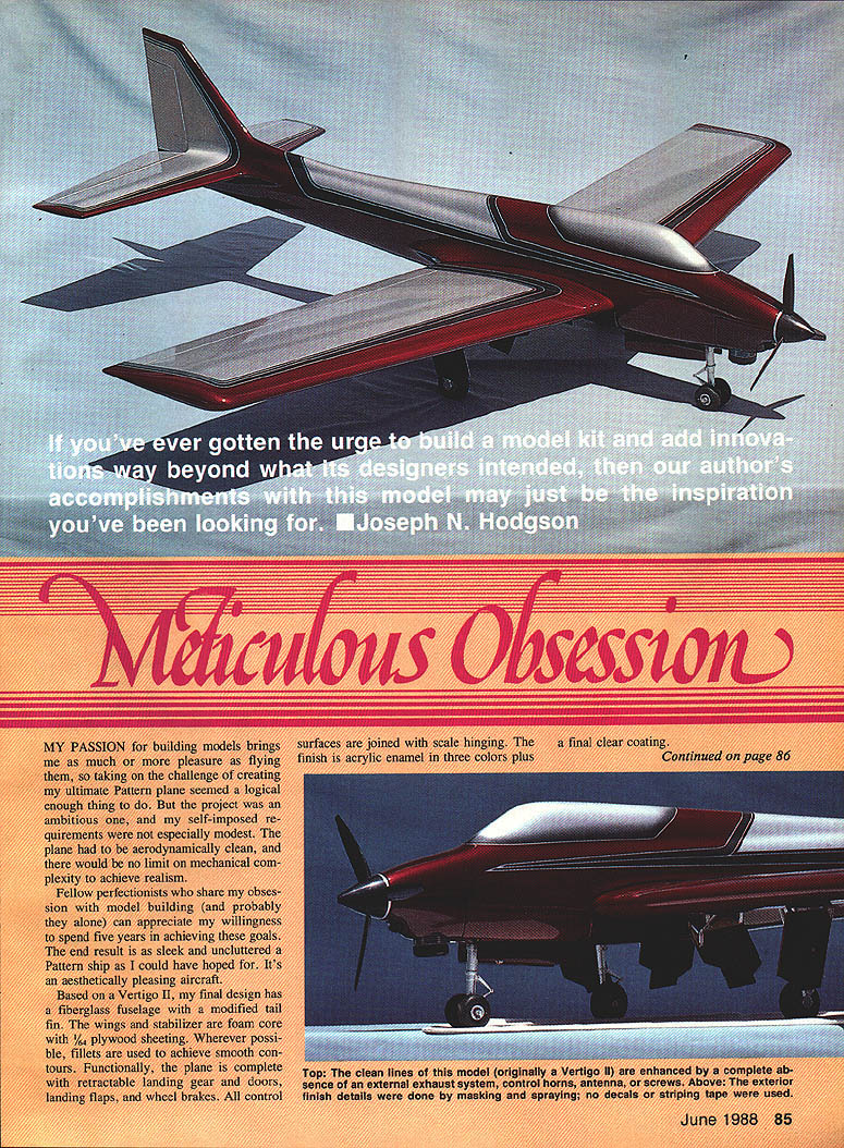

Meticulous Obsession
My passion for building models brings me as much or more pleasure as flying them, so taking on the challenge of creating my ultimate Pattern plane seemed a logical thing to do. The project was ambitious, and my self-imposed requirements were not modest. The plane had to be aerodynamically clean, and there would be no limit on mechanical complexity to achieve realism.
Fellow perfectionists who share my obsession with model building can appreciate my willingness to spend five years achieving these goals. The end result is as sleek and uncluttered a Pattern plane as I could have hoped for—an aesthetically pleasing aircraft.
Based on a Vertigo II, the final design has a fiberglass fuselage with a modified tail fin. The wings and stabilizer are foam core with 1/64" plywood sheeting. Wherever possible, fillets are used to achieve smooth contours. Functionally, the plane is complete with retractable landing gear and doors, landing flaps, and wheel brakes. All control surfaces are joined with scale hinging. The finish is acrylic enamel in three colors plus a final clear coating.
Major features include:
- Retractable landing gear with precision doors
- Landing flaps and wheel brakes
- Internal manifolding and tuned pipe exhaust
- Series fuel tanks with pump and overflow routing
- Scale hinges, hidden hardware, and realistic mechanical action
Mechanical complexities
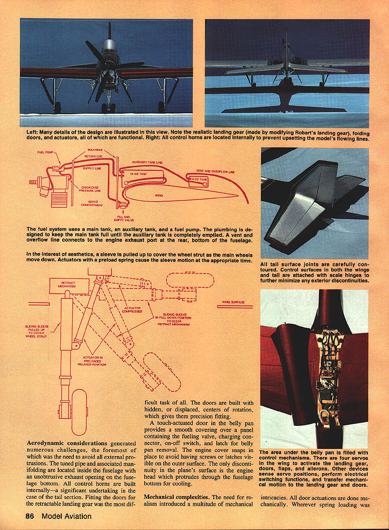
The need for realism introduced a multitude of mechanical intricacies. All door actuations are done mechanically. Wherever spring loading was required, or a preload was desired to provide a positive feel in the operation, springs were used. The mechanical systems are designed such that the landing gear, doors, flaps, and all moving parts operate in a scale, realistic manner.
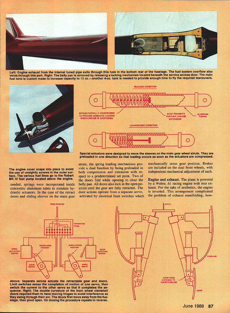
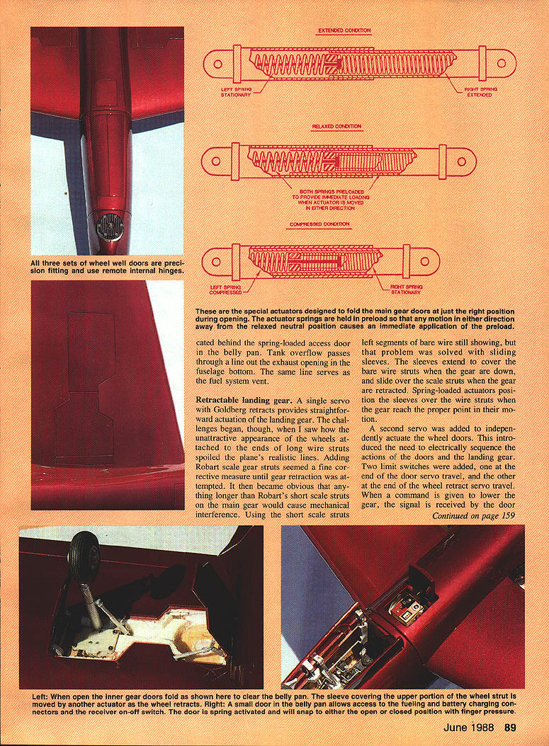
The area under the belly pan is filled with small mechanisms. There are four servos in the wing to activate the landing gear, doors, flaps, and ailerons. Other devices sense servo positions, perform electrical switching functions, and transfer mechanical motion to the landing gear and doors. The various fuel lines run to a Robart MK IV fuel pump located above the engine. As needed, springs were incorporated inside concentric aluminum tubes to simulate hydraulic actuators. In the retract doors and sliding sleeves on the main gear struts, the spring-loading mechanisms provide a dual function by being preloaded in both compression and extension relative to a predetermined set point. Two of the doors fold while opening to clear the belly pan. All doors lock in the open position until the gear are fully retracted. The door actions operate from a separate servo, activated by electrical limit switches which mechanically sense gear position. Brakes are included on the dual front wheels, with independent mechanical adjustment of each.
In the interest of aesthetics, a sleeve is pulled up to cover the wheel strut as the main wheels move down. Actuators with a preload spring cause the sleeve motion at the appropriate time.
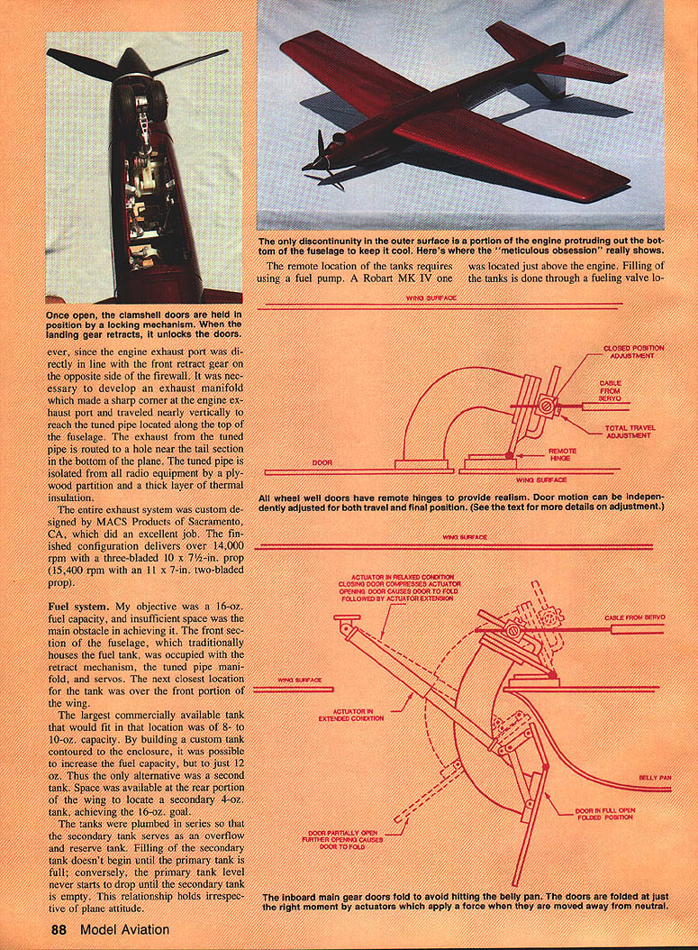
A touch-actuated door in the belly pan provides a smooth covering over a panel containing the fueling valve, charging connector, on-off switch, and latch for belly pan removal. The engine cover snaps in place to avoid having screws or latches visible on the outer surface. The only discontinuity in the plane's surface is the engine head, which protrudes through the fuselage bottom for cooling.
Engine and exhaust
The plane is powered by a Webra .61 racing engine with rear exhaust. For the sake of aesthetics, the engine is inverted. This arrangement complicated the problem of exhaust manifolding, however, since the engine exhaust port was directly in line with the front retract gear on the opposite side of the firewall. It was necessary to develop an exhaust manifold that made a sharp corner at the engine exhaust port and traveled nearly vertically to reach the tuned pipe located along the top of the fuselage. The exhaust from the tuned pipe is routed to a hole near the tail section in the bottom of the plane. The tuned pipe is isolated from all radio equipment by a plywood partition and a thick layer of thermal insulation.
The entire exhaust system was custom designed by MACS Products of Sacramento, CA, which did an excellent job. The finished configuration delivers over 14,000 rpm with a three-bladed 10 x 7-1/2" prop (15,400 rpm with an 11 x 7" two-bladed prop).
Fuel system
My objective was a 16-oz. fuel capacity, and insufficient space was the main obstacle. The front section of the fuselage, which traditionally houses the fuel tank, was occupied with the retract mechanism, the tuned pipe manifold, and servos. The next closest location for the tank was over the front portion of the wing.
The largest commercially available tank that would fit in that location was 8 to 10 oz. By building a custom tank contoured to the enclosure, it was possible to increase capacity to only 12 oz. Thus the only alternative was a second tank. Space was available at the rear portion of the wing to locate a secondary 4-oz. tank, achieving the 16-oz. goal.
The tanks were plumbed in series so that the secondary tank serves as an overflow and reserve tank. Filling of the secondary tank doesn't begin until the primary tank is full; conversely, the primary tank level never starts to drop until the secondary tank is empty. This relationship holds irrespective of plane altitude.
The remote location of the tanks requires a fuel pump. A Robart MK IV pump is located just above the engine. Filling of the tanks is done through a fueling valve located in the bottom of the fuselage, behind the spring-loaded access door in the belly pan. Tank overflow passes through a line out the exhaust opening in the fuselage bottom; the same line serves as the fuel system vent.
Retractable landing gear
A single servo with Goldberg retracts provides straightforward actuation of the landing gear. The challenges began when I saw how the unattractive appearance of wheels attached to the ends of long wire struts spoiled the plane's realistic lines. Adding Robart scale gear struts seemed a fine corrective measure until gear retraction was attempted. It then became obvious that anything longer than Robart's short scale struts on the main gear would cause mechanical interference. Using the short scale struts left segments of bare wire still showing, but that problem was solved with sliding sleeves. The sleeves extend to cover the bare wire struts when the gear are down and slide over the scale struts when the gear are retracted. Spring-loaded actuators position the sleeves over the wire struts when the gear reach the proper point in their motion.
Special actuators were designed to fold the main gear doors at the right position during opening. The actuator springs are held in preload so that any motion in either direction away from the relaxed neutral position causes an immediate application of the preload.
A second servo was added to independently actuate the wheel doors. This introduced the need to electrically sequence the actions of the doors and the landing gear. Two limit switches were added: one at the end of the door servo travel and the other at the end of the wheel retract servo travel. When a command is given to lower the gear, the signal is received by the door servo. When the door servo reaches the end of its travel—i.e., the doors are fully opened—the limit switch that connects the wheel servo is tripped and the wheels are lowered. The retract command activates the reverse sequence. When the wheels are fully retracted, the wheel retract servo limit switch is tripped and the door servo is activated to close the doors.
Landing gear doors
Designing the doors taxed my fund of ingenuity. The ground rules were that the doors should be precision fitted and that all hinges should be hidden. It followed that the hinges had to have remote locations. On the main gear doors, the hinges were located back inside the wing about one inch from the doors. This arrangement allows the doors not only to rotate but also to immediately clear the wing surface when opening begins.
The solution for locating the front gear door hinges was less straightforward. Because of the double curvature of these clamshell doors, remote hinging would have to be at least 1/2" away; these hinges would interfere with other fuselage structure. Since the fuselage is not wide enough to accommodate the required remote hinge locations, an alternate scheme had to be devised.
The answer was to make the hinges themselves movable. Each of the four hinges on the doors is built into concentric aluminum tubing sliders. When the doors are actuated to the open position, the first motion that occurs is hinge movement. The doors move away from the fuselage about 1/8" without beginning any rotational motion. As actuation continues, the doors rotate to the open position. Upon closing, the sequence reverses: the doors first rotate to the closed position, and then move in unison 1/8" until they're flush with the fuselage.
On the main gear doors, achieving the proper door travel required special mechanisms. The lever arm, which spans the distance between the hinge and the actuator cable attachment point, was made adjustable on each door. This adjustment controls the magnitude of the angle that the door sweeps. A second adjustment varies the length of the actuation cable, providing control of the door stopping position. Simultaneously setting these adjustments regulates the arc of door travel from closed to open. The front gear doors required no special method of adjustment; excess motion is absorbed by a spring linkage in the actuation cable.
All doors lock once they reach the fully open position to ensure wind loading cannot accidentally partially close a door and prevent wheel retraction. The main gear doors lock open by a gravity-actuated lock, which is deactivated by the wheels when they reach full retract position. The front door lock is more elaborate: the clamshell sections have spring-loaded pins that slide into position when the doors are fully open. The pins are withdrawn by the action of front wheel retraction.
An unexpected problem was discovered with the inboard main gear doors: they could not be opened far enough because they were extending into the belly pan. Either the entire retract system had to be moved, or a folding section adjacent to the door had to be incorporated into each inboard door. The latter design was selected. Hinging the doors was simple enough, but having them fold and unfold at just the right point was another matter. The folding action required that the hinged section have an actuator which would push during part of the door travel and then pull for the remainder of the motion.
The necessary dual action was achieved with actuators that have two internal springs, one preloaded in compression and the other preloaded in tension. The results were excellent. For about three-quarters of the door opening motion, no folding occurs. At the point the doors rapidly fold, and remain folded for the rest of the opening motion. The converse actions occur when the doors close.
Building a Pattern plane as intricate as this one obviously took time, imagination, and patience. In this article I've covered only the more significant design features involved. The whole project was challenging but fun. Each step was enjoyable as it came; in retrospect, I wouldn't want to do it again. I anticipate building many more planes, but from now on my aspirations will be more conventional.
Transcribed from original scans by AI. Minor OCR errors may remain.

