
Michael's Mustang
Model building is somewhat contagious, partially genetic—and frequently addictive. How else could it spread so fast? I caught it early, at about age six. My oldest son, Michael, was hooked a bit earlier, and each of my other children seems to be affected in varying degrees from time to time. So far, Michael shows every sign of being incurable.
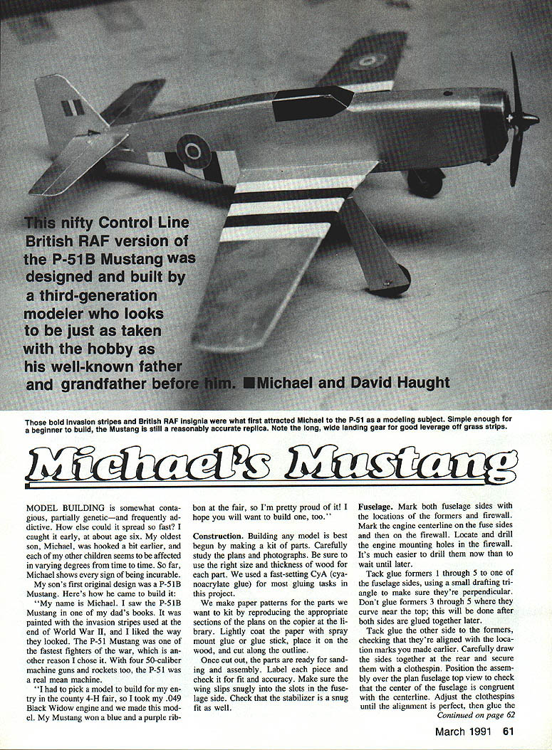
"My name is Michael. I saw the P-51B Mustang in one of my dad's books. It was painted with the invasion stripes used at the end of World War II, and I liked the way they looked. The P-51 Mustang was one of the fastest fighters of the war, which is another reason I chose it. With four .50-caliber machine guns and rockets too, the P-51 was a real mean machine.
"I had to pick a model to build for my entry in the county 4-H fair, so I took my .049 Black Widow engine and we made this model. My Mustang won a blue and a purple ribbon at the fair, so I'm pretty proud of it! I hope you will want to build one, too."
Construction
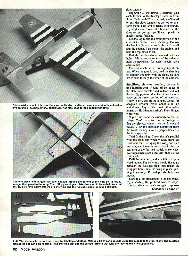
Building any model is best begun by making a kit of parts. Carefully study the plans and photographs. Be sure to use the right size and thickness of wood for each part. We used a fast-setting CyA (cyanoacrylate) glue for most gluing tasks in this project.
We make paper patterns for the parts we want to kit by reproducing the appropriate sections of the plans on the copier at the library. Lightly coat the paper with spray mount glue or a glue stick, place it on the wood, and cut along the outline.
Once cut out, the parts are ready for sanding and assembly. Label each piece and check it for fit and accuracy. Make sure the wing slips snugly into the slots in the fuselage side. Check that the stabilizer is a snug fit as well.
Fuselage
- Mark both fuselage sides with the locations of the formers and the firewall. Mark the engine centerline on the fuselage sides and then on the firewall. Locate and drill the engine mounting holes in the firewall now — it's much easier than waiting until later.
- Tack-glue formers F1 through F5 to one fuselage side, using a small drafting triangle to ensure they're perpendicular. Do not glue formers F3 through F5 where the curve near the top will be formed after both sides are glued together.
- Tack-glue the other side to the formers, checking alignment with your location marks. Draw the sides together and secure the rear with clothespins. Position the assembly over the plan fuselage top view and check that the fuselage center is congruent with the centerline. Adjust clothespins until alignment is perfect, then glue the sides together.
- Beginning at the firewall, securely glue each former to the fuselage sides in turn. Since F3 through F7 are curved you'll need to pull the sides together at the top; conforming isn't as tricky as it sounds. Glue one former at a time and let the CyA set. When done you'll end up with a nicely shaped fuselage.
- Cut the top block for the front portion and cockpit from 1/4-in. sheeting. Hollow the block slightly to clear both the firewall and the engine. Test-mount the engine and trim the top block to fit.
- Drill the needle-valve access and fuel-tank holes. File a groove on the top to hold a screwdriver for easier needle-valve adjustments.
- Cut and attach 1/16-in. fuselage top sheeting. When the glue is dry, sand the sheeting to contour smoothly to the sides. Be careful not to sand through the wood at the corners.
Stabilizer, elevator, rudder, bellcrank and landing gear
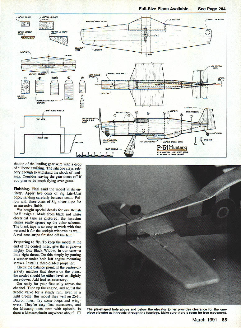
- Round off the edges of the stabilizer, elevator and rudder. Cut out the two 1/32-in. plywood doublers and glue them in place on the center section of the elevator. Allow to dry and fit the hinges. Check for adequate elevator travel — about 3/8 in. up and down. Small, thin nylon hinges or Sig Manufacturing's Easy Hinges work well.
- Slip-fit the stabilizer assembly into the fuselage. You will likely need to trim the fuselage so the elevator clears on its downward travel. View stabilizer alignment from the front, making sure it's perpendicular to the fuselage sides.
- Trial-fit the wing. Check that it is parallel with the stabilizer when viewed from the front and rear. Bringing the wing and stabilizer into alignment now is important to the appearance of the finished model. Make any necessary adjustments and set the parts aside.
- Drill the bellcrank and attach it to its plywood mount. The bellcrank should fit snugly between the fuselage sides just under the wing position. Slide the wing into place and pin securely. Fit and pin the bellcrank mount.
- Starting at its attachment to the bellcrank, begin bending the pushrod wire to shape. Note that the wire travels straight to approximately where the wing trailing edge begins, then gently bends upward toward the elevator horn. Trim the wire about 2 in. overlength.
- Mount the elevator horn to the elevator. Slip the stabilizer back in its slot, holding it in place with pins and tape while you finish bending the pushrod to hook up the elevator. Check that the stabilizer moves freely through the full range of elevator travel before gluing it in place.
- Don't forget to add the tailwheel strut and balsa blocking (a small wedge cut from trailing edge stock fits nicely) to secure the stabilizer. Glue everything thoroughly with CyA.
- Carefully glue the top of the wing to the fuselage, leaving the bottom free. Bend the landing gear from 1/16-in. music wire, slip it through the bottom of the wing slot in the fuselage, and clip it in place with clothespins. Glue the gear to the wing using a tiny bit of CyA at a time.
- Thoroughly coat one side of each 1/32-in. plywood landing-gear plate with white glue, then clamp it securely over the wires and up against the fuselage. Glue the bottom of the wing to the fuselage.
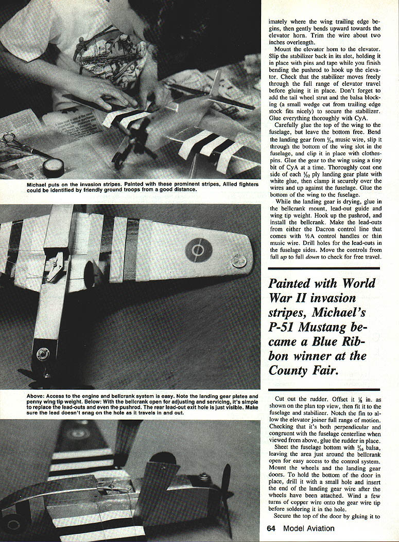
- While the landing gear is drying, glue in the bellcrank mount, lead-out guide and wingtip weight. Hook up the pushrod and install the bellcrank.
- Make the lead-outs from either the Dacron control line that comes with 1/2A control handles or thin music wire. Drill holes for the lead-outs in the fuselage sides. Move the controls from full up to full down to check for free travel.
- Cut out the rudder. Offset it 1/16 in. as shown on the plan top view, then fit it to the fuselage and stabilizer. Notch the fin to allow the elevator joiner full range of motion. Check that the rudder is both perpendicular and congruent with the fuselage centerline when viewed from above, then glue it in place.
- Sheet the fuselage bottom with 1/16-in. balsa, leaving the area just around the bellcrank open for easy access to the control system.
- Mount the wheels and the landing-gear doors. To hold the bottom of the door in place, drill it with a small hole and insert the end of the landing-gear wire after the wheels have been attached. Wind a few turns of copper wire onto the gear wire tip before soldering it in the hole. Secure the top of the door by gluing it to the fuselage.
Finishing
Final-sand the model in its entirety. Apply five coats of Sig Lite-Coat dope, sanding carefully between coats. Follow with three coats of Sig silver dope for an attractive finish.
We purchased special decals for our British RAF insignia. The invasion stripes were made from black and white electrical tape, which really spruce up the color scheme. The black tape is easy to work with and was also used for the cockpit windows. A red nose stripe finished off the trim.
Preparing to fly
- To keep the model at the end of the control lines, give the engine — a Cox Black Widow in our case — a little right thrust. Do this by putting a washer under both left engine mounting screws. Install a three-bladed propeller.
- Check the balance point. If the center of gravity matches that shown on the plans, the model should be either level or slightly nose-down. Add lead as necessary.
- Tune up the engine and adjust the needle valve for a steady run. Even in a light breeze, this model flies well on 25-ft. Dacron lines. Try some loops and wing-overs; they're easy first maneuvers, and the Mustang does them with aplomb.
Is there a Messerschmitt anywhere about?
Transcribed from original scans by AI. Minor OCR errors may remain.

