
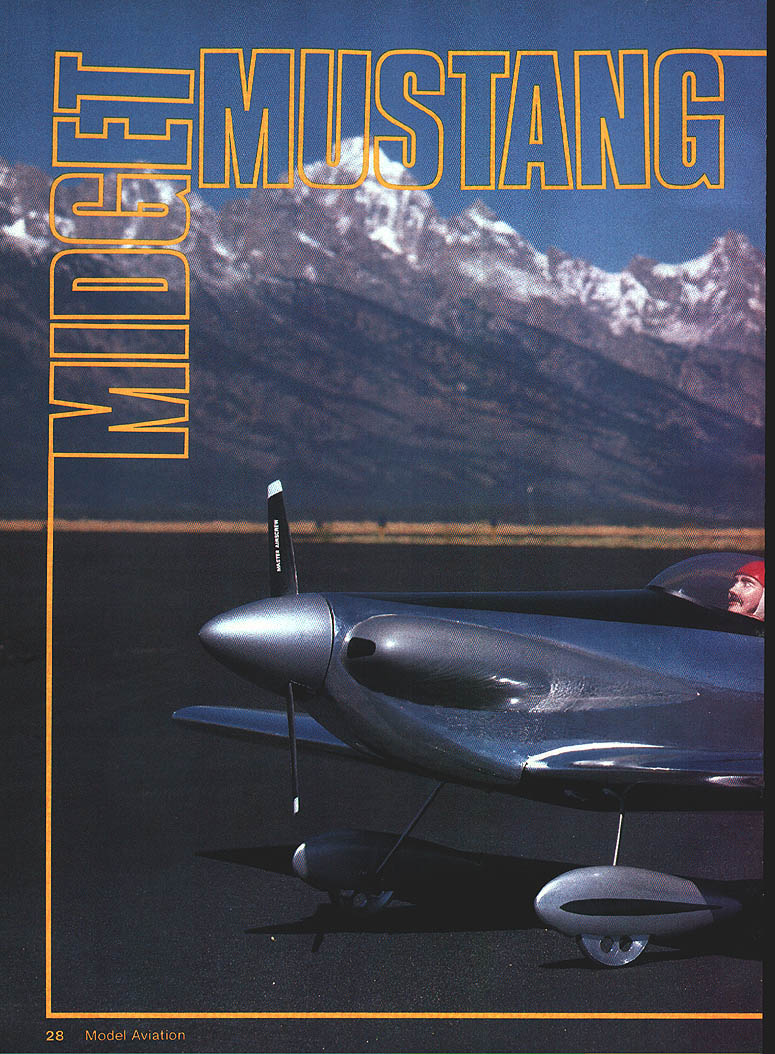
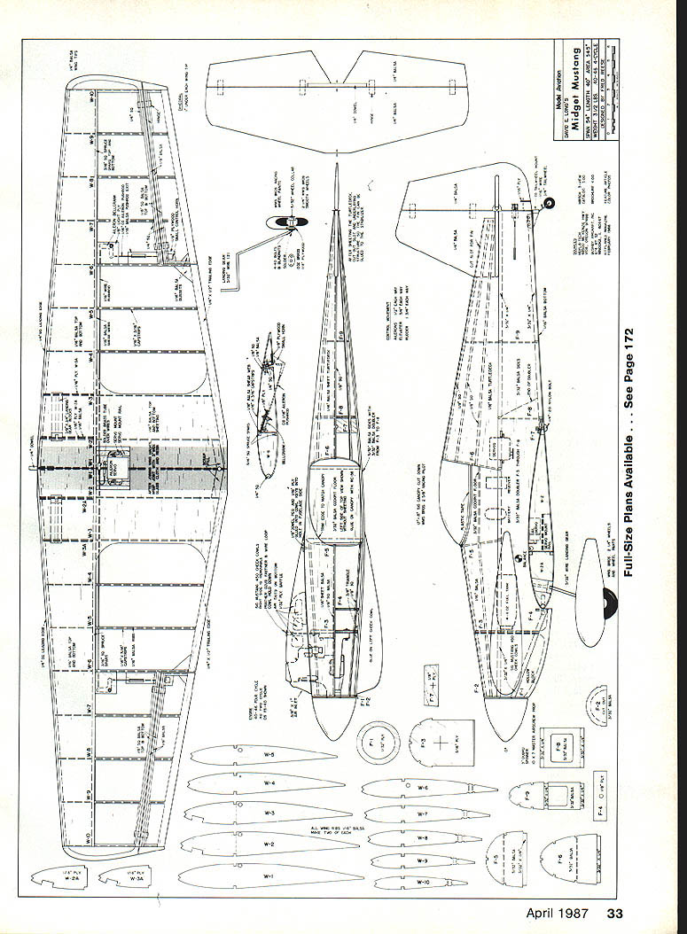
Midget Mustang
Fred Reese
Introduction
With a .40-size four-stroke engine and lightweight construction as per the plans and instructions, this semiscale radio-control model is amazingly versatile and forgiving in flight.
Last year I designed and built a lightweight sport-pattern model called the Swallow, which turned out to be a really fine flying machine. The Swallow, along with a lightweight scale Taylorcraft built by fellow club member Harry Stewart, became the inspiration for a contest we called the 3-1/2-lb. Four-Cycle Challenge. The rules called for a scale model weighing not more than 3-1/2 lb., with a wing area of at least 450 sq. in., and powered by a four-cycle .40 to .46 engine. Simple scale judging and an uncomplicated flying routine coupled with a barbecue almost doubled the anticipated turnout.
I designed and built the Midget Mustang for that challenge. The full-size plane has always attracted me (particularly the polished-aluminum look of the P‑Shooter and other race Mustangs), and I knew someday I'd have to have one.
A Brief History
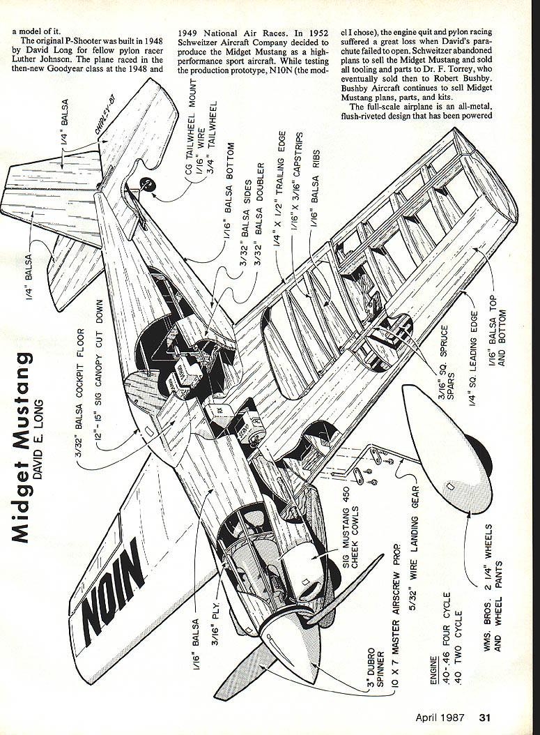
- The original P‑Shooter was built in 1948 by David Long, a pylon racer. Luther Johnson flew it in the new Goodyear class at the 1948–49 National Air Races.
- In 1952 the Schweitzer Aircraft Company tested a production prototype of the Midget Mustang. After Long suffered a fatal accident (parachute failure following an engine failure while pylon racing), Schweitzer abandoned plans to sell the Midget Mustang and sold the tooling and parts.
- Dr. F. Torrey later sold the tooling and parts to Robert Bushby. Bushby Aircraft continues to sell Midget Mustang plans and parts kits.
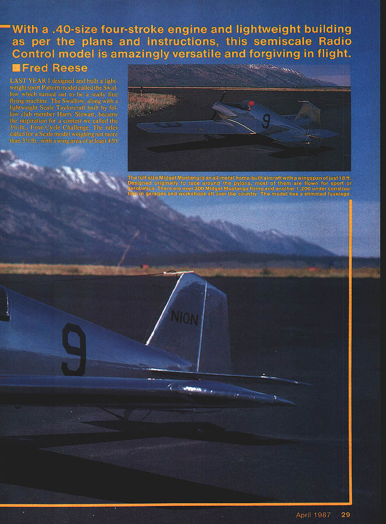
- The full-scale Midget Mustang is an all-metal, flush-riveted design, stressed to 9 Gs and well suited to aerobatics. It has been powered by engines from roughly 65 to 150 hp and cruises about 175 mph with a 135-hp engine. Variants have included retractable gear, tricycle gear, folding wings, and the two-place Mustang II.
There are approximately 300 Midget Mustangs flying and another 1,200 under construction across the country.
Design Objectives and Scale
- Objective: produce a pattern-capable scale model using O.S. or Enya four-cycle .40 engines (quiet, lower rpm/power than two-strokes) while keeping the model light for spirited performance.
- Scale: wing is exactly quarter scale; fuselage is slightly smaller (closer to fifth scale). The fuselage was slimmed by 1/8 in. in width and height to allow use of a 3-in. spinner (Du-Bro and CB both make 3-in. spinners).
- Weight: complete airframe, ready to fly (less radio and engine), should weigh about 1-1/2 lb.
If using an Enya .46, consider moving the wing forward 1/16 in. and adjusting formers F-4, F-7, and F-8 to fit the larger engine and tank.
Flight Characteristics
- With a .40 four-stroke the Midget Mustang will happily fly the IMAC Sportsman pattern and performs clean inside/outside square loops and figure eights. Wing is near-symmetrical and needs a touch of down elevator inverted.
- Knife-edge flight is good due to large fuselage side area, requiring little aileron correction.
- Snap rolls are not strong—wing forgivingness and light wing loading resist quick-breaking stalls. Sharpening the leading edge near the tips or adding triangular stock to the leading edge can help. Moving the balance aft (toward the spar) increases snap-roll performance but makes the elevator sensitive.
- Takeoffs: excellent—requires slight right rudder as the tail comes up, stays on mains until lift-off; can do realistic smooth takeoffs or be ripped off in 10 ft.
- Landings: require practice because of very low flying speed and light wing loading—you must start the pattern farther out and lower than other models; the final flair is smooth if not rushed.
- Lightly loaded models fly better at high altitudes (e.g., Wyoming).
Construction Overview
General approach: build using typical model techniques but with lighter/thinner wood. Use Zap CA+ for most construction. Be careful handling the thin balsa shell tissue.
Materials & adhesives
- Fuselage sides: 3/32-in. balsa, with a 3/32-in. doubler through the radio compartment.
- Top of fuselage: 1/16-in. light, straight-grained balsa, stiffened with 1/16-in.-sq. stringers.
- Wing ribs and sheeting: 1/16-in. balsa; spars: 3/16-in.-sq. spruce (or 1/4-in.-sq. hard balsa).
- Use Zap CA+ for gluing (including firewall and gear blocks).
- Covering: EconoKote or MonoKote; chrome MonoKote is an option (difficult to work), Sig Polykote chrome also available.
- Finish protection: Balsarite (brush at least one coat in radio compartment and seams around engine bulkheads for oil/fuel protection).
Cutting parts
- Put small parts on the end of the plan and photocopy for cutting.
- Glue two sheets of wood together and cut both wing rib sets simultaneously with spray contact or rubber cement between sheets; peel apart afterward.
- True parts with a sanding block.
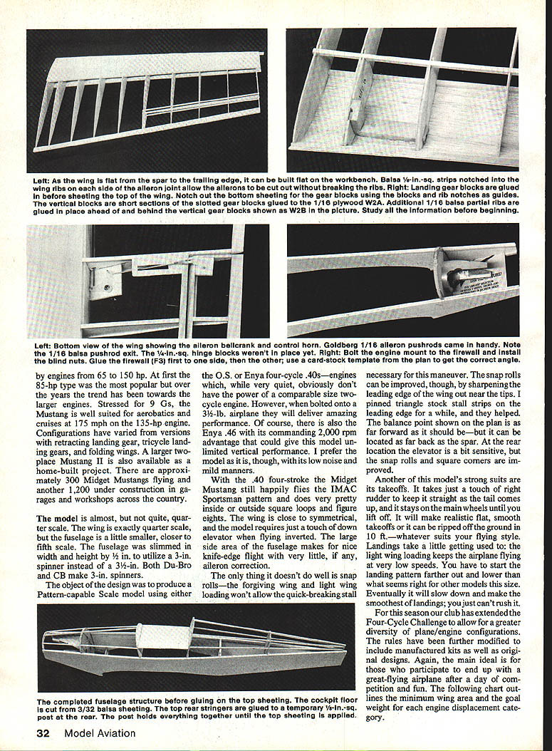
Wing Construction
- Pin bottom leading edge sheet to wax-paper-covered plan.
- Glue 3/16-in.-sq. spruce bottom spar to back edge of bottom sheet (1/4-in.-sq. hard balsa is an alternate).
- Pin trailing edge (1/4 x 3/8 in.); taper trailing edge before building.
- Pin 1/16-in. balsa strip ahead of trailing edge to hold ribs up 1/16 in. for cap strips.
- Glue ribs W-1 and W-10; glue 1/16-in. plywood doublers to W-2 and W-3; finish ribs and add top spar.
- Glue on 1/16-in.-sq. leading edge; pull up bottom sheet and glue to ribs/leading edge.
- Cut slots in bottom sheeting for landing gear blocks (use notches in W-2 and W-3 as guides). Glue gear blocks; add vertical blocks and 1/16-in. reinforcement front/back of vertical block. Drill 3/32-in. through vertical block and landing gear block for wire gear.
- Pin wing flat and glue top front 1/16-in. sheeting. Glue 1/16-in. vertical-grained shear webs between spars and ribs (pin wing flat to avoid twist).
- Ailerons: glue in 1/16-in.-sq. top and bottom pieces so ailerons can be cut out without breaking ribs. Face ailerons/back edge with 1/8-in. sheet for a light cap strip. Notch ribs for 1/4-in.-sq. aileron spars so top edge is even with cap strip. Glue cap strip and center sheeting.
- Install 3/32-in. light-ply bellcrank mounts and control horn mounts; use 1/8-in. wire pushrods cut 1/8 in. longer for overlap and soldering. Hole in rib W-4 acts as a bearing for pushrod.
- Install aileron bellcranks and Goldberg 1/16-in. aileron pushrods; attach control horns to ailerons with two #2 sheet-metal screws (these will hold).
- Glue on 1/4-in. balsa pushrod exits and 1/4-in. balsa wing tips.
- Sand root ends to dihedral and glue halves together. Set one tip 2 in. under (use W-10). No spar joiners: strength at center is provided by 3-in.-wide fiberglass cloth and resin. Fillet with resin + microballoons; blot excess with tissue; sand and finish.
Fuselage Construction
- Cut sides; glue 3/8 x 1/4-in. strip down top edge from nose to tail. Glue balsa doubler from front firewall to past F-8; doubler back edge extends past F-8 at an angle for 1/2 in. Add 3/32 x 1/4-in. strip from nose to F-4 along bottom.
- Cut firewall F-3 from 3/32 ply; attach engine mount with 4-40 bolts and blind nuts.
- Make a cardstock template for firewall angle from top view; glue firewall to one fuselage side then glue on the second side.
- Cut other bulkheads; glue on 3/8 x 1/4-in. strips to stiffen balsa bulkheads. Glue in F-4 and F-8, pull tail together and glue. Add F-9, F-7, F-5, F-6 and cockpit floor. Glue F-2 and 5/8-in.-sq. top forward stringers. Add 3/16-in.-sq. tail post and top rear 1/4-in.-sq. stringers.
- Top 1/16-in. sheeting applied in two pieces (F-2 to F-6 and F-6 to tail post). Choose light straight-grained balsa and piece sheets slightly oversize. Tape forward sheet in place and mark canopy opening; cut opening smaller than canopy for later trimming.
- Add cockpit detail before gluing top front sheet (paint instrument panel/seat and install pilot). Apply bead of glue along top 5/8-in. stringer and glue top front sheet; pull sides down and trim to fit. Repeat for top rear sheet, making relief cut down center at rear as needed for bend. Dampen outside after gluing to help form.
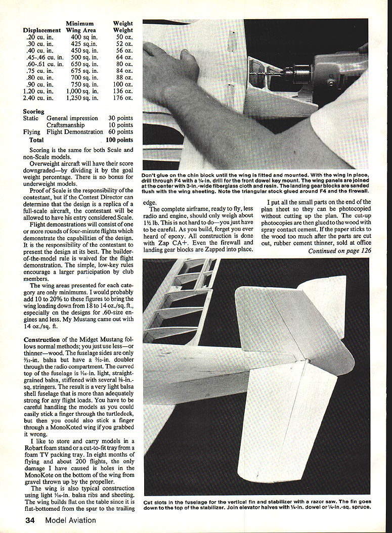
Tail Surfaces
- Cut fin and stabilizer from 1/8-in. light balsa; sand to symmetrical airfoil.
- Sand elevator as one piece; do not cut the V for the rudder until after shaping and gluing in the 1/16-in. dowel joiner.
- Cut slot through turtledeck for fin; cut carefully to avoid weakening stringer ends. Cut stabilizer slots in turtledeck sides; glue stabilizer to top edge of sides, then glue fin into slot and to stabilizer top.
- Finish sand fuselage and tail with #200 sandpaper. Remove engine and mount, then brush Balsarite over fuselage and seams around F-4 and F-7. Lightly sand off any fuzz.
Engine Installation and Cowling
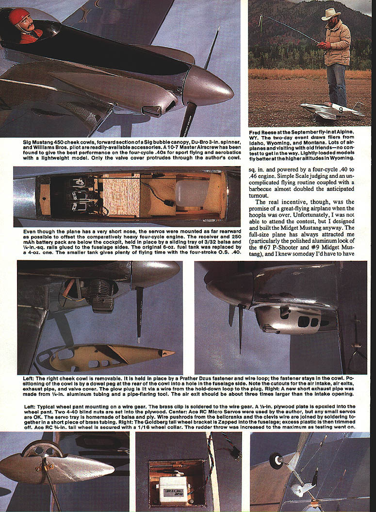
- Use a Sig Mustang 450 cheek cowl (fit cheek cowls to fuselage sides). Paint left cowl before final fitting; fit right cowl without engine first, then install engine and make cutouts.
- Cut air inlet and exit holes; exit should be about three times the size of the intake. Glue in air baffle and rear positioning peg; drill matching 1/4-in. hole in fuselage side.
- Cowl mounting: Prather Dzus fasteners for cheek cowl, wire-loop fastener for the cowl front. Dzus fastener locks with quarter-turn; install by drilling hole with 1/64-in. drill bit. Wire loop attaches to firewall with sheet-metal screws; secure and Zap to keep stable.
- Valve cover may protrude through cowl; make a wire hold-down loop for glow plug and solder a ground/start wire as needed.
- Exhaust: short 1-in. aluminum pipe from 3/8-in. tubing (pipe flaring tool) works well; this directs oil/exhaust under wing and keeps airframe cleaner. Make a cutout for exhaust. Wrap insulated wire around glow plug and solder to loop for starting battery leads. Use alligator clips on the loop and exhaust pipe for starting.
Landing Gear & Wheel Pants
- Typical wheel pant mounting: wire gear, a brass clip soldered to wire gear, and 1/8-in. plywood plate epoxied in wheel pant. Two 4-40 blind nuts in plywood secure attachment.
- Goldberg tailwheel bracket works well; trim excess plastic where bracket mounts. Ace RC 1/4-in. tailwheel secured with 1/16-in. wheel collar.
- Increase rudder throw for better ground handling.
- Wheels: originally used Formula One racing wheels (light), but “O” ring wheels transmitted landing shock and cracked wing sheeting above gear blocks. Switched to Du-Bro 2-3/16-in. wheels and problem stopped. These can be used with built-up pants or Sig/Cessna 150 plastic pants.
- Wheel pants on wire gear can rack backward on hard landing and tear covering; on this design the covering only tears and patches easily. Williams Bros. slimmer racing wheel pants are noted on the plan.
Radio, Servos & Pushrods
- Use Ace RC micro servos or small servos; nose servos should be mounted as far forward as possible to offset four-cycle engine weight.
- Receiver and 250 mAh battery pack fit below cockpit on a sliding tray made from 3/32-in. balsa with 1/4-in.-sq. rails glued to fuselage sides (foam padding and sliding sheet for access).
- Servo tray homemade from balsa plywood. Use 1/4-in.-sq. balsa pushrods with 1/16-in. wire bent at right angles at servo end; adjustable clevises at control horns. Wrap wire-to-balsa joints with thread and secure with a drop of Zap.
- Bellcranks: glue 3/32-in. light-ply bellcrank mounts in wing; use 1/8-in. wire pushrods overlapped and soldered with a short piece of brass tubing over the joint.
Fuel Tank
- Original 6-oz. tank replaced with a 4-oz. tank to reduce nose weight—gives plenty of flying time with a four-stroke .05 to .40 engine.
- If using a two-stroke .40 or Enya .46, a larger tank will be needed.
Covering, Paint & Canopy
- Cover with EconoKote or MonoKote. Chrome MonoKote is an option (harder to work); Sig’s chrome Polykote may be easier.
- Trim: Coverite Graphics trim sheets (thin vinyl; fuel-proof) available in red, black, white, yellow, and blue. Vinyl is fuel-proof and does not shrink with heat (it will melt if overheated).
- Canopy: forward part of a Sig 12–15-in. bubble canopy works well. Lay canopy over plan to find matching section. Back edge overlaps turtledeck and F-6 by about 3/16 in. Leave 1/8-in. edge for gluing, pierce covering every 1/8 in. to allow glue to wick, and glue canopy with RC-56. Apply 1/4-in. colored plastic tape around canopy joint for a neat finish.
- Paint cheek cowls and spinner: Pactra Formula U silver works well. Chrome epoxy sprays are not fuel-proof.
Flight Trim, Testing & Performance Tips
- During taxi and initial flight testing, adjust throws and verify center of gravity. Increase maximum throw in elevator and rudder if needed for improved maneuverability.
- Light wing loading and forgiving nature allow recovery from stalls with power; the model is rock-solid stable with no tendency to tip-stall.
- Prop: Master Airscrew 10x7 gave the best performance with four-cycle .40–.46 on this lightweight model.
- At IMAC Nationals the author and others flew uninterrupted sequences and still had several minutes of fuel remaining with the 4-oz tank on a four-stroke .40.
- For high-altitude flying, keep model lightly loaded.
Other Notes & Final Impressions
- Construction is conventional but light: fuselage shell is thin and requires careful handling. Store and carry in a Robart foam stand or cut-to-fit foam tray.
- In about eight months and 200 flights, only minor covering damage occurred (gravel kick-up under prop).
- The Swallow and the Midget Mustang are the author's two favorite light O.S. FS-40 models—very similar in size, power, weight, and configuration. Both are exceptionally pleasant to fly and have improved the author's piloting skills, especially landings.
- The Midget Mustang is versatile, forgiving, and fun—capable of relaxed sport flying, IMAC Sportsman maneuvers, and impressive scale-style performance.
Transcribed from original scans by AI. Minor OCR errors may remain.

