
Midi-slow
Dave Clarkson
Introduction
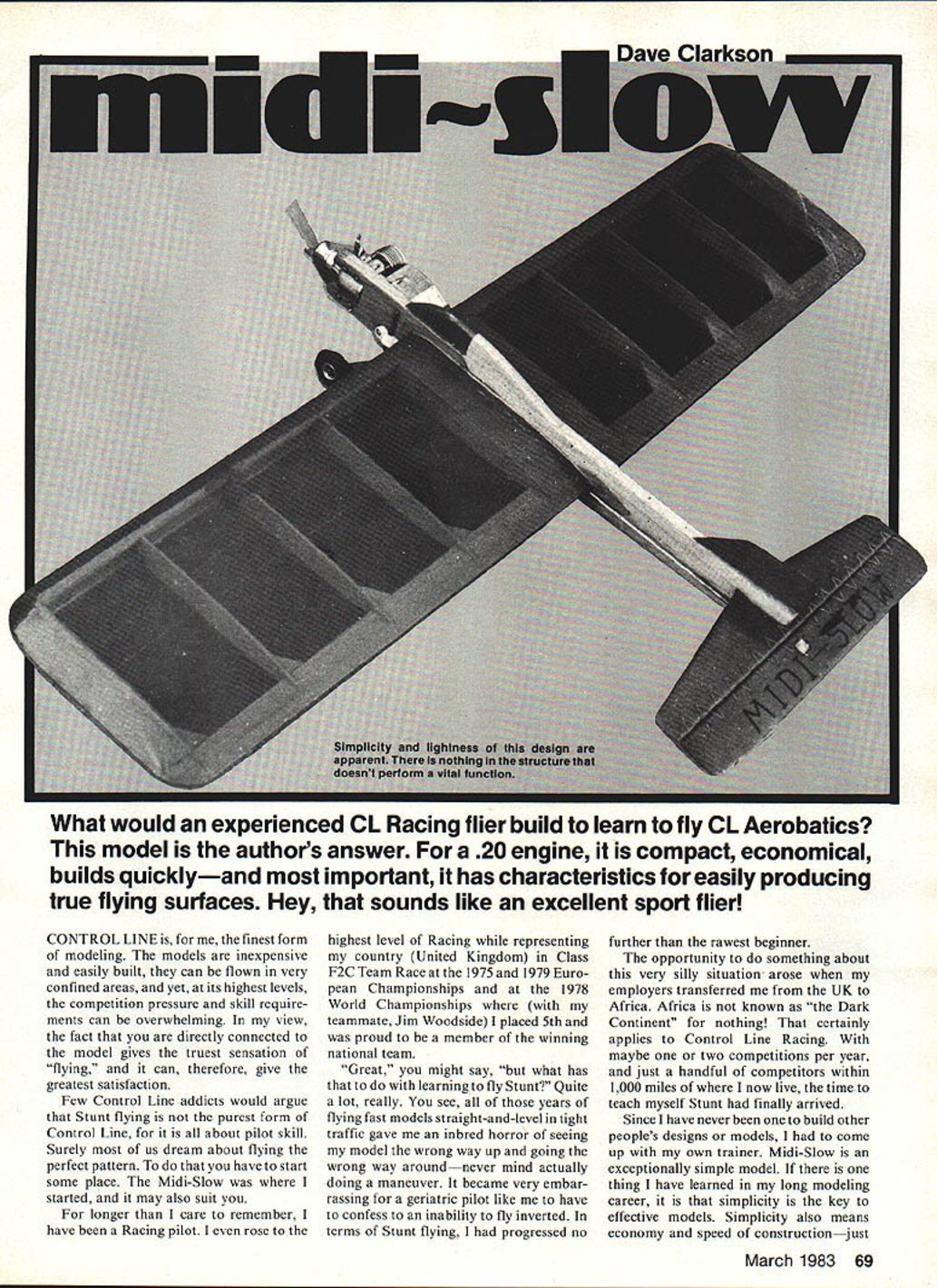
What would an experienced C/L Racing flier build to learn to fly C/L Aerobatics? This model is the author's answer. For a .20 engine, it is compact, economical, builds quickly—and, most important, it has characteristics for easily producing true flying surfaces. Hey, that sounds like an excellent sport flier!
Control Line is, for me, the finest form of modeling. The models are inexpensive and easily built, they can be flown in very confined areas, and yet, at its highest levels, the competition pressure and skill requirements can be overwhelming. In my view, the fact that you are directly connected to the model gives the truest sensation of "flying," and it can, therefore, give the greatest satisfaction.
Few Control Line addicts would argue that Stunt flying is not the purest form of Control Line, for it is all about pilot skill. Surely most of us dream about flying the perfect pattern. To do that you have to start someplace. The Midi-Slow was where I started, and it may also suit you.
Background
For longer than I care to remember, I have been a Racing pilot. I even rose to the highest level of Racing while representing my country (United Kingdom) in Class F2C Team Race at the 1975 and 1979 European Championships and at the 1978 World Championships where (with my teammate, Jim Woodside) I placed 5th and was proud to be a member of the winning national team.
"Great," you might say, "but what has that to do with learning to fly Stunt?" Quite a lot, really. All of those years of flying fast models straight-and-level in tight traffic gave me an inbred horror of seeing my model the wrong way up and going the wrong way around—never mind actually doing a maneuver. It became very embarrassing for a geriatric pilot like me to have to confess to an inability to fly inverted. In terms of Stunt flying I had progressed no further than the rawest beginner.
The opportunity to do something about this arose when my employers transferred me from the UK to Africa. Africa is not known as "the Dark Continent" for nothing! That certainly applies to Control Line Racing. With maybe one or two competitions per year, and just a handful of competitors within 1,000 miles of where I now live, the time to teach myself Stunt had finally arrived.
Since I have never been one to build other people's designs or models, I had to come up with my own trainer. Midi-Slow is an exceptionally simple model. If there is one thing I have learned in my long modeling career, it is that simplicity is the key to effective models. Simplicity also means economy and speed of construction—just the things to suit beginners. The Midi-Slow flies nice and slow with good line tension, impressive stability, and more than adequate maneuverability.
Some of you, when viewing the plan, will look at the airfoil and go no further. True, it is not an NACA 0018, or some other scientific profile, but those of you who saw Richard Wilkins' Combat models at the 1975 AMA Nationals (at Lake Charles) will recognize it and know that it works. I believe that it was no less a Combat personality than Sherwood Buckstaff who, on seeing Wilky's models before they flew, gave his polite opinion that, with such an airfoil, their flight could not be anything but poor. Next day, after seeing them perform, Sherwood drawled to Richard, "I have an apology to make—those models sure do fly." I am not saying that this UK-style "flat" airfoil is better than an NACA 0018, but it really helps in getting a quickly built, light and strong, warp-free wing which "sure do fly."
Key design and construction notes
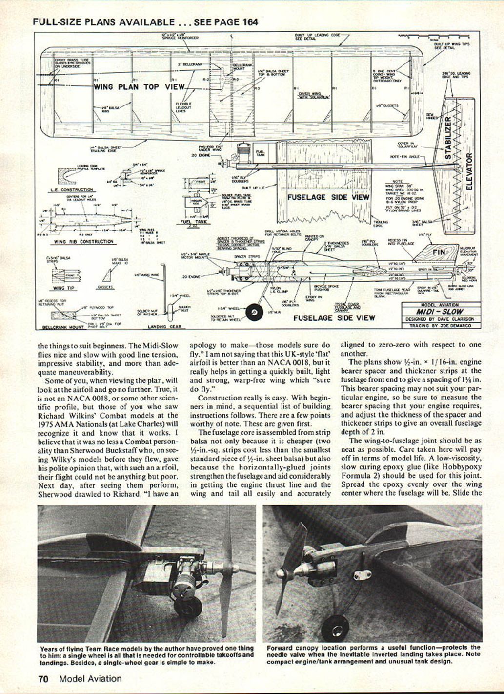
- The fuselage core is assembled from strip balsa because it is cheaper (two 1/2-in.-sq. strips cost less than the smallest standard piece of 1/8-in. sheet balsa). Horizontally-glued joints strengthen the fuselage and aid considerably in getting the engine thrust line and the wing and tail all easily and accurately aligned to zero-zero with respect to one another.
- The plans show 1/2-in. x 1/16-in. engine bearer spacer and thickener strips at the fuselage front end to give a spacing of 1 1/8 in. This spacing may not suit your particular engine, so measure the bearer spacing your engine requires and adjust the thickness of the spacer and thickener strips to give an overall fuselage depth of 2 in.
- The wing-to-fuselage joint should be as neat as possible. Use a low-viscosity, slow-curing epoxy (like Hobbypoxy Formula 2) for this joint. Spread epoxy evenly over the wing center where the fuselage will be, slide the wing into the fuselage, measure to make sure it is square and centered, then fillet the joint with the same epoxy using your fingers—rub hard to force epoxy well into the joint.
- Select unflawed, straight-grain balsa of the strengths specified on the plans. If you cut out wing and tail components carefully, you will only need one sheet each of 1/8 x 4, 3/16 x 3, and 1/4 x 3 balsa. Careful cutting of the wing and tail covering film will result in only a 26 x 36-in. piece of covering material being needed.
Construction details and tools
- When I refer to "epoxy," I mean the low-viscosity, slow-curing type (like Hobbypoxy Formula 2). "Glue" means an aliphatic wood glue (like Sig-Bond).
- For cutting out balsa and thin plywood parts, use a steel rule and a strong knife with a new blade. Use a vise and a small hacksaw to cut out the bellcrank platform and the engine bearers.
- I use a lot of sticky tape to hold things together while glue sets, augmenting this with pins and clothespins when gluing fuselage doublers and wing center sheeting.
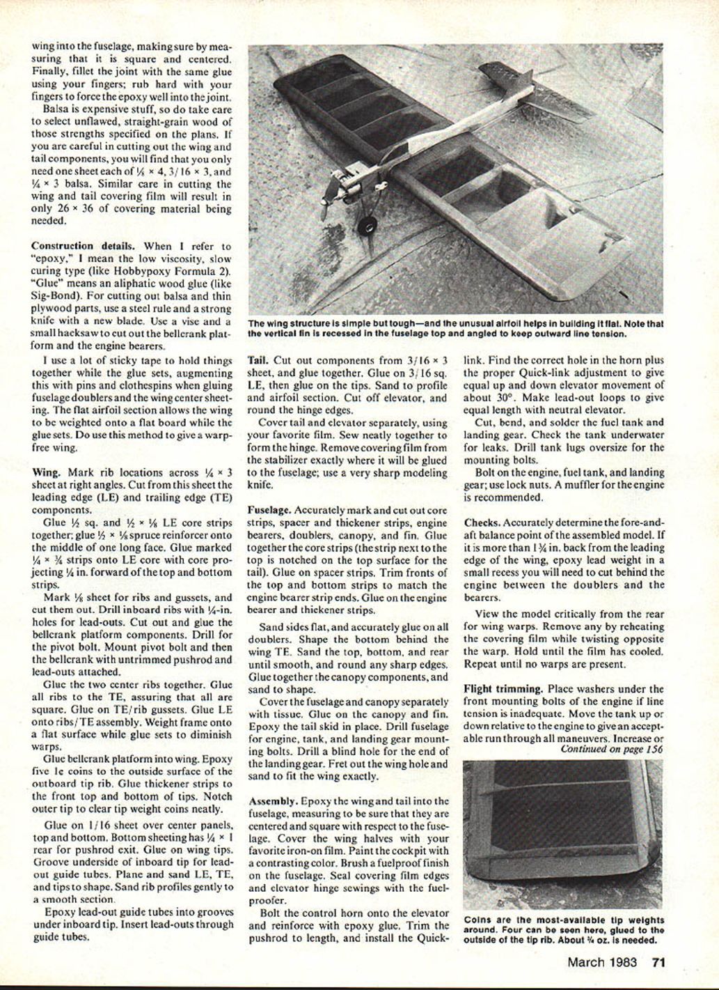
- The flat airfoil section allows the wing to be weighted onto a flat board while the glue sets—do use this method to give a warp-free wing.
Wing (assembly steps)
- Mark rib locations across 1/4 x 3 sheet at right angles. Cut from this sheet the leading edge (LE) and trailing edge (TE) components.
- Glue 1/8 sq. and 1/16 x 1/8 LE core strips together; glue 1/8 x 1/16 spruce reinforcer onto the middle of one long face.
- Glue marked 1/4 x 3 strips onto the LE core with the core projecting 1/8 in. forward of the top and bottom strips.
- Mark 1/8 sheet for ribs and gussets, and cut them out. Drill inboard ribs with 1/4-in. holes for lead-outs.
- Cut out and glue the bellcrank platform components. Drill for the pivot bolt, mount the pivot bolt, and then the bellcrank with untrimmed pushrod and lead-outs attached.
- Glue the two center ribs together. Glue all ribs to the TE, assuring that all are square. Glue on TE/rib gussets. Glue LE onto the ribs/TE assembly.
- Weight the frame onto a flat surface while the glue sets to diminish warps.
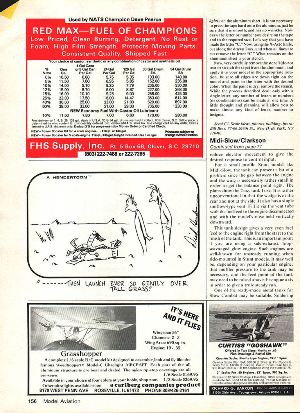
- Glue the bellcrank platform into the wing. Epoxy five one-cent coins to the outside surface of the outboard tip rib. Glue thickener strips to the front top and bottom of tips. Notch outer tip to clear tip weights neatly.
- Glue on 1/16-in. sheet over center panels, top and bottom. Bottom sheeting has 1/4 x 1 rear for pushrod exit. Glue on wing tips.
- Groove underside of inboard tip for lead-out guide tubes. Plane and sand LE, TE, and tips to shape. Sand rib profiles gently to a smooth section.
- Epoxy lead-out guide tubes into grooves under the inboard tip. Insert lead-outs through guide tubes.
Tail
- Cut out components from 3/16 x 3 sheet, and glue together.
- Glue on 3/16 sq. LE, then glue on the tips. Sand to profile and airfoil section.
- Cut off elevator and round the hinge edges.
- Cover tail and elevator separately with your favorite film. Sew neatly together to form the hinge.
- Remove covering film from the stabilizer exactly where it will be glued to the fuselage; use a very sharp modeling knife.
Fuselage
- Accurately mark and cut out core strips, spacer and thickener strips, engine bearers, doublers, canopy, and fin.
- Glue together the core strips (the strip next to the top is notched on the top surface for the tail). Glue on spacer strips. Trim fronts of the top and bottom strips to match the engine bearer strip ends. Glue on the engine bearer and thickener strips.
- Sand sides flat, and accurately glue on all doublers. Shape the bottom behind the wing TE. Sand the top, bottom, and rear until smooth, and round any sharp edges.
- Glue together canopy components and sand to shape.
- Cover the fuselage and canopy separately with tissue. Glue on the canopy and fin.
- Epoxy the tail skid in place. Drill fuselage for engine, tank, and landing gear mounting bolts. Drill a blind hole for the end of the landing gear. Fret out the wing hole and sand to fit the wing exactly.
Assembly
- Epoxy the wing and tail into the fuselage, measuring to be sure that they are centered and square with respect to the fuselage.
- Cover the wing halves with your favorite iron-on film. Paint the cockpit with a contrasting color. Brush a fuelproof finish on the fuselage.
- Seal covering film edges and elevator hinge sewings with epoxy.
- Bolt the control horn onto the elevator and reinforce with epoxy glue. Trim the pushrod to length, and install the quick-link.
- Adjust the control horn/quick-link to give equal up and down elevator movement of about 30°.
- Make lead-out loops to give equal length with neutral elevator.
- Cut, bend, and solder the fuel tank and landing gear. Check the tank underwater for leaks. Drill tank lugs oversize for the mounting bolts.
- Bolt on the engine, fuel tank, and landing gear; use lock nuts. A muffler for the engine is recommended.
Checks
- Accurately determine the fore-and-aft balance point of the assembled model. If it is more than 1 3/8 in. back from the leading edge of the wing, epoxy lead weight in a small recess you will need to cut behind the engine between the doublers and the bearers.
- View the model critically from the rear for wing warps. Remove any by reheating the covering film while twisting opposite the warp. Hold until the film has cooled. Repeat until no warps are present.
Flight trimming
- Place washers under the front mounting bolts of the engine if line tension is inadequate.
- Move the tank up or down relative to the engine to give an acceptable run through all maneuvers.
- Increase or reduce elevator movement to give the desired response to control input.
For a small profile Stunt model like Midi-Slow, the tank can present a bit of a problem since the gap between the engine and the wing is necessarily rather small in order to get the balance point right. The plans show the 2-oz. tank I use. It is rather unconventional in that the wedge is at the rear and not at the side. It also has a single uniflow-type vent. Fill it via the vent tube with the fuel feed to the engine disconnected and with the model's nose held vertically downward.
This tank design gives a very even fuel feed to the engine right from the start to the finish of the tank. This is an important point if you are using a side-exhaust, loop-scavenged glow engine. Such engines are well-known for unsteady running when side-mounted in Stunt models. Depending on your particular engine, muffler pressure to the tank may be necessary, and the feed point of the tank may need to be raised above the engine axis in order to give a truly steady run.
One of the ready-made metal tanks for Slow Combat may be suitable. Soldering tanks is one of the skills needed for Control Line, so you might as well begin now. The tin-plate of a soft drink can is ideal for tank construction, provided that the paint on the outside and the lacquer on the inside are scrubbed off using a wet Brillo pad. Lapping all of the joints and using a powerful electric soldering iron (I use a 60W iron, and it is only just powerful enough), plus lots of flux (and cleanliness) is the way to ensure no leaks.
Wait for a calm day to do the trimming flights. You will learn nothing in windy conditions except, perhaps, that you are a brave fool!
Any .20 cu. in. engine should prove acceptable. This size engine is inexpensive and widely available. When equipped with a muffler, it should be quiet enough to keep most of the populace content.
The sharp-eyed among you will have noticed that Midi-Slow is equipped with an old, smelly diesel — a MK III Oliver Tiger. The Oliver is a lovely old engine with impeccable manners, but it is far from common and not ideal for Stunt.
A good friend in the UK has built a Midi-Slow using a muffled OS .20 glow engine, and he reports that this combination is ideal. If you are intending to use such an engine, an 8 x 6 nylon prop and 52 ft. of .012 Pylon Brand lines will prove best and give Midi-Slow the flight characteristics I have found with mine.
Final thoughts
Can I now fly Stunt? Well, the old saying about old dogs and new tricks has a lot of truth to it, but Midi-Slow has been a great aid for me in trying to prove that this saying is not always true. For the beginner who does not have any prejudices built in by many years of Control Line Racing experience, the transition from straight-and-level flying to the full AMA C/L pattern recognizably, if not beautifully, should come easily with Midi-Slow.
Some of you may be thinking that Midi-Slow may be a perfect stepping stone, but boy is it ugly! Even I would not boast about its looks, but what do you build for a Stunt trainer? Beauty is about bottom of the list of concerns. Ease, speed, economy of construction, and flight performance are what you need—and Midi-Slow has these aplenty. Save that beautiful model plan for when Midi-Slow has done its job and you can fly Stunt properly. I have—and I'm glad I did.
Transcribed from original scans by AI. Minor OCR errors may remain.

