
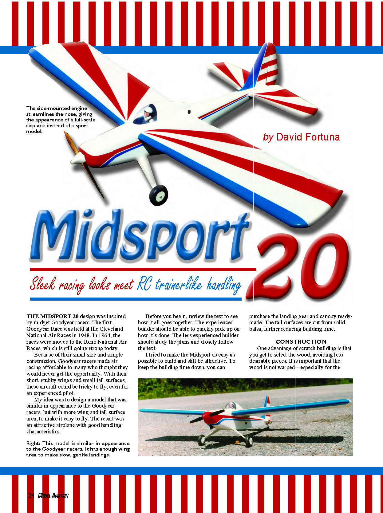
Midsport 20 - 2009/07
Sleek racing looks meet RC trainer-like handling
by David Fortuna
The Midsport 20 design was inspired by midget Goodyear racers. The first Goodyear Race was held at the Cleveland National Air Races in 1948. In 1964, the races were moved to the Reno National Air Races, which is still going strong today.
Because of their small size and simple construction, Goodyear racers made air racing affordable to many who thought they would never get the opportunity. With their short, stubby wings and small tail surfaces, these aircraft could be tricky to fly, even for an experienced pilot.
My idea was to design a model similar in appearance to the Goodyear racers, but with more wing and tail surface area to make it easy to fly. The result was an attractive airplane with good handling characteristics.
Before you begin, review the text to see how it all goes together. The experienced builder should be able to quickly pick up on how it's done. The less experienced builder should study the plans and closely follow the text.
I tried to make the Midsport as easy as possible to build and still be attractive. To keep the building time down, you can purchase the landing gear and canopy ready-made. The tail surfaces are cut from solid balsa, further reducing building time.
Specifications
- Type: RC sport
- Skill level: Beginner builder, intermediate pilot
- Wingspan: 55 inches
- Wing area: 497 square inches
- Length: 37.75 inches
- Weight: 4 pounds
- Construction: Balsa and plywood
- Finish: Builder’s choice (author used silk and paint)
- Other: 4-ounce fuel tank, four-channel radio with four standard servos, 2-inch spinner, 2.5-inch main wheels, aluminum landing gear, clear bubble canopy
- Engine/motor: .25–.32 two-stroke / 500 watts
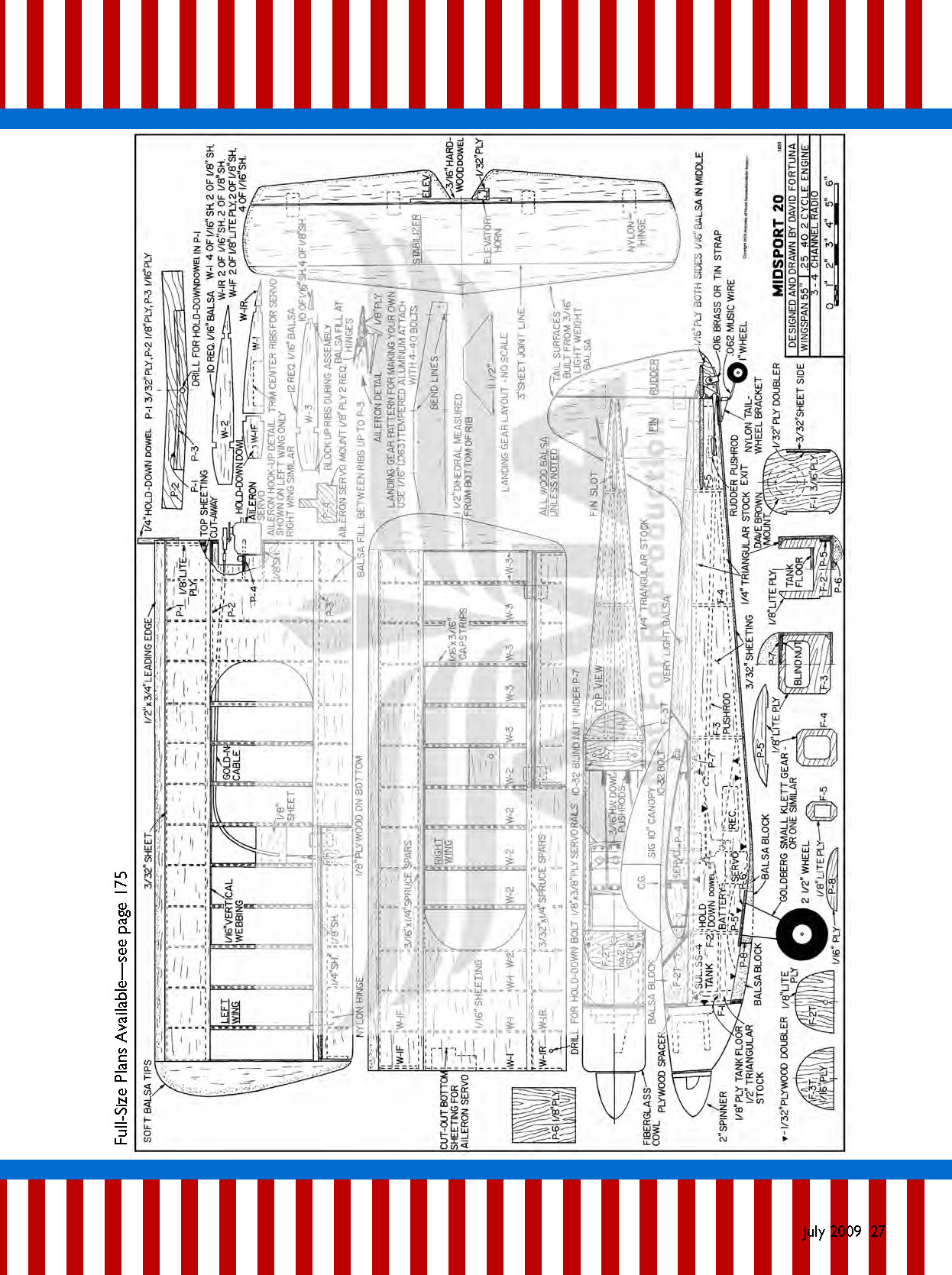
- Full-size plans available — see Page 175
Construction
One advantage of scratch building is that you get to select the wood, avoiding less-desirable pieces. It is important that the wood is not warped—especially for the wing spar, wing sheeting, and tail surfaces.
The wing ribs and fuselage sides are cut from C-grain balsa. The wing sheeting should be a softer grade of wood that bends easily, such as A-grain. The tail surfaces and the rear fuselage top block are cut from medium-soft balsa—very light, or 4- to 6-pound stock.
Spruce is used for the wing spars. It is only a bit heavier than balsa but is much stronger and has less tendency to warp. Best results come from using a slow-setting glue for maximum penetration of glue joints.
Plywood is specified as either aircraft plywood or light plywood. Use aircraft plywood on heavy-stress areas, and light plywood where density is required.
Please forgive me for not having taken pictures of the wing while building the prototype. Studying the plans should suffice for the builder.
Tail Surfaces
Since there is not much here, it’s a good place to start. The entire tail is built from 3/16-inch sheet balsa. I used 3-inch sheets and joined them as shown on the plans. Notice that the wood grain varies on the fin.
- Elevators are joined with a 3/16-inch hardwood dowel. Epoxy and microballoons are used to fair it all in. At the elevator horn, 1/32-inch plywood was recessed to keep the horn from crushing the balsa.
- The bottom part of the rudder is made from 1/16-inch balsa, sandwiched between pieces of 1/16-inch plywood.
- I used Du-Bro nylon hinges on the elevators and rudder.
Wing
Take your time and work accurately when building the wing. How well the model performs depends largely on how precisely the wing is built. If warps are built into it, it is almost impossible to eliminate them after the wing is finished.
- Cut the ribs and punch holes for the aileron control rods. An easy way to make the holes is to sharpen a piece of brass tube and twist the tube as you press it into the rib.
- Cut the 3/16 x 1/4-inch bottom spars to length, and epoxy them to dihedral brace P-2. After it’s dry, you are ready to build one side of the wing.
- Start on the left panel (or the right if you prefer) by pinning down the 3/16 x 1/4-inch main spar and attached brace. Doing so will raise the right spar due to the dihedral angle. By building the wing this way, the wing becomes a complete unit, assuring that it all fits together.
- Pin a 1/8-inch square fixture strip under the leading-edge (LE) portion of the ribs. You can add a similar strip at the trailing edge (TE) if needed.
- Glue in ribs, starting with W-2 and W-3. Although the plans show rib W-3 in two pieces, it’s easier to glue it in one piece and cut it later for the ailerons.
- Glue rib sections W-1, checking alignment against the other ribs. Add front rib sections W-1F. Cut out the center ribs for the hold-down dowel and epoxy the dowel in. Then add front wing brace P-1 and the 3/32-inch LE. Now add the front and rear top spars.
- After the wing panel is dry, remove it from the building board. Block the left wing panel up and pin the right main spar down; build the right panel onto the left.
- Add the bottom 3/32 x 1/4-inch rear spar, wing brace P-3, and rib sections W-1R. Sheet the bottom of the wing and cut out the ailerons. There will be a 3/16-inch gap between the aileron sheeting and rear wing spar—add a 1/8-inch balsa TE behind the rear spar at the aileron and balsa between the rear spars where hinges are to go.
- Trim aileron ribs for the LE. Glue the LE in place and add plywood for the aileron horn mount.
- To mount the aileron servo, cut the bottom sheeting out as shown on the plans. The servo mounts to P-4, which should be cut to fit your servo. Route Sullivan Products Gold-N-Cable through the wing with a threaded coupler used on the aileron end. Use an aileron connector and Du-Bro Ball Link Dual Take-Off on the servo end.
- Once hooked up and working properly, add the top wing sheeting and then the 1/2 x 3/4-inch LE and wingtips. Wingtips are made from lightweight balsa and can be carved out on the inside to reduce weight.
- Plans show 1/16-inch vertical webbing between the wing ribs. I did not add vertical webbing on my model, but my flying method doesn’t put a lot of stress on the wing. If you use a larger engine or fly more aggressively, add vertical webbing.
- Add wing capstrips. These should be medium-soft balsa, which bends easily.
- After sanding and shaping the LE, glue 2-inch-wide fiberglass tape along the center section as reinforcement. Use 15-minute epoxy or slow CA to put this down.
- Balsa that makes the top part of the fuselage is glued on the wing center section at a later time.
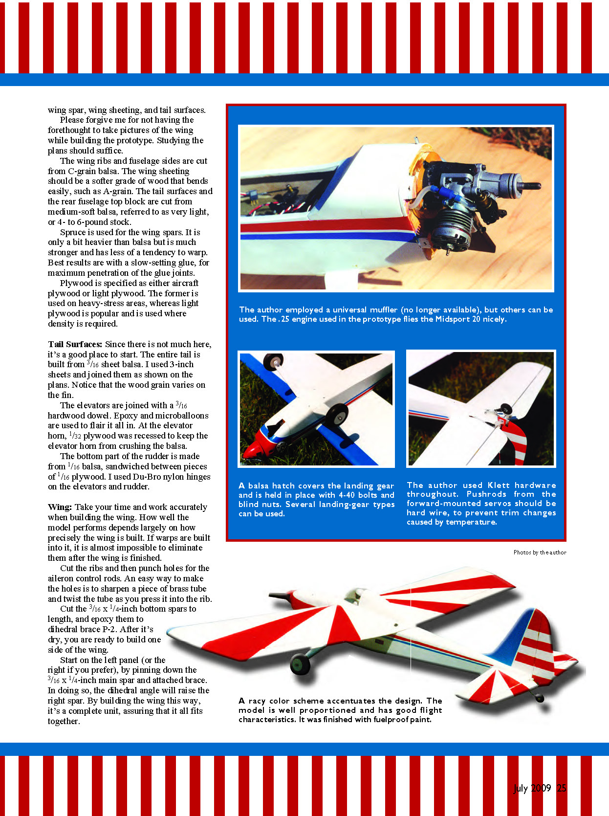
A racy color scheme accentuates the design. The model is well proportioned and has good flight characteristics. It was finished with fuelproof paint.
Fuselage
- Cut the sides from 3/32-inch balsa. Make the right side 3/32 inch shorter at the nose to provide right thrust.
- Cut 1/32-inch plywood nose doublers and glue them in place. The doublers are glued inside the 1/4-inch triangular stock, so leave a 1/4-inch border for this. Make a left and right side.
- Bevel the 1/4-inch triangular stock at the rear using the top view, then glue it in place. Note the triangular stock extends past the sides at the bottom just behind the landing gear; trim flush after gluing.
- Mark the fuselage formers’ locations on the fuselage sides and cut out for landing-gear plate P-6, stabilizer opening, and pushrod exits at the rear. Glue in the 1/8-inch light-plywood doubler P-5 around the landing-gear cutout. Glue balsa in the tail inside the triangular stock and sand to shape.
- All fuselage formers are cut from plywood. F-1 is 3/16-inch plywood, the remaining formers are 1/8-inch light plywood. Glue F-2 and F-3 to one side of the fuselage and ensure they are 90° to the side. When dry, add the other side.
- Before epoxying in F-1, decide what engine you will use and how you will mount it. I used a Dave Brown Products mount and a .25 engine. With this setup I added a 3/8-inch plywood spacer behind the mount; alternatively, you can use a long mount.
- I chose a Du-Bro universal muffler extending out the cowl bottom. It is no longer available, but others can be used. The .25 engine used in the prototype flies the Midsport 20 nicely.
Pushrods and controls:
- Popular pushrod types include Du-Bro Lazer Pushrods or Sullivan Gold-N-Rods. When using these, glue supports on the fuselage formers and epoxy the rods in.
- I made pushrods from 3/16-inch-diameter dowel rods. Make a 5/64-inch hole 3/4 inch from the end of the dowel. Make a 90° bend 5/16 inch from the end of a 2-56 rod and insert this end in the drilled hole. Secure the metal rod to the dowel by wrapping it tightly with strong cord (e.g., 1/2A flying-line thread) and coating it with epoxy or cyanoacrylate.
- Servos are mounted on 1/8 x 3/8-inch plywood rails glued to the fuselage sides, with 3/16 x 1/4-inch balsa strips glued under the rails. Servos might need to be shifted slightly for balance—ensure they don't interfere with the aileron servo.
With the rudder and elevator in place, check controls for smooth operation and make certain that no binding occurs. For control throws I used:
- Rudder: 1/2 inch
- Elevator: 1/2 inch up, 1/4 inch down
- Aileron: 1/2 inch up, 3/8 inch down
Sheet the rear bottom section of the fuselage, and glue the rear top block in place. Use extremely light balsa for it; you can carve the inside portion of the block to a 1/4-inch wall thickness to reduce weight. Glue F-3T in place.
Mount the wing, glue balsa on top of the wing as shown on the plans, and open the wing-bolt holes. Shape and sand the entire top deck and wing center section together. Glue the fin in place.
Cowl
You can make a simple, open-ended sport cowl by gluing 1/4-inch balsa sheet to the fuselage sides, leaving the top and bottom open. This setup works best for an upright engine installation.
I made a fiberglass cowl using the balloon method:
- Make a cowl plug from sheet and block balsa. Sand the structure to shape, leaving it 1/32 inch undersized.
- Glue a 3/8-inch-diameter dowel about 3 inches long on the back of the cowl; hold it in place by putting the dowel in a vise.
- Drape Saran Wrap over the cowl, then heavyweight fiberglass cloth. Hold the cloth in place with thumbtacks pushed into the back of the cowl.
- Coat the cloth with slow-drying (15- or 30-minute) epoxy. Inflate a balloon and push it over the cowl while slowly letting the air out. The balloon should be large enough that it doesn't burst when forced over the cowl. Have more than one balloon available.
- Once the balloon is over the cowl, let it set overnight. Then peel off the balloon and add another layer of fiberglass cloth. Sand the cowl and fuselage together so they match up.
Covering and Finishing
- Fill any imperfections with lightweight spackling paste. Make fillets with epoxy and microballoons.
- Carefully sand the model with 320-grit paper, and apply the covering of your choice.
- I covered the fuselage and tail with medium-weight silkspan and the wing with Dave Brown Products Skyloft. This bonded nylon material is inexpensive, lightweight, and extraordinarily strong.
- My finishing method: apply two coats of clear dope to the entire model, followed by a light sanding, then dope the covering in place and trim.
- Brush on two coats of clear dope, followed by four coats of a dope/talcum powder mix (or use sanding sealer). After drying for several days, sand with 320- and 400-grit paper until most of the buildup is removed.
- Epoxy the canopy in place, tape it, and spray the model with colored dope for a lightweight, scale-type finish that is durable and easy to touch up.
Flying
- Epoxy the control surfaces in place and check the controls. Make sure they move in the correct direction.
- The model should balance on the main spar, with the nose level or pointing slightly down.
- Do a radio range check and inspect the model carefully—many crashes are caused by small things that were overlooked.
- If you have flown several sport models, the Midsport 20 should present no problems. Make the first flights on a calm day. If the model is out of trim, wind will only make things worse.
Everything went smoothly on the first flight; only a small trim adjustment was needed. That was the result of thoroughly checking for warps and alignment during construction, making sure the balance was right, and verifying that everything worked correctly before flying.
Many happy flights! David Fortuna 5065 Wards Rd. Evington, VA 24550
Sources
- Du-Bro — (800) 848-9411 — www.dubro.com
- Carl Goldberg Products / Great Planes Model Distributors — (800) 637-7660 — carlgoldbergproducts.com
- Sullivan Products — (410) 732-3500 — www.sullivanproducts.com
- Sig Manufacturing — (641) 623-5154 — www.sigmfg.com
- Dave Brown Products — (513) 738-1576 — www.dbproducts.com
Transcribed from original scans by AI. Minor OCR errors may remain.

