
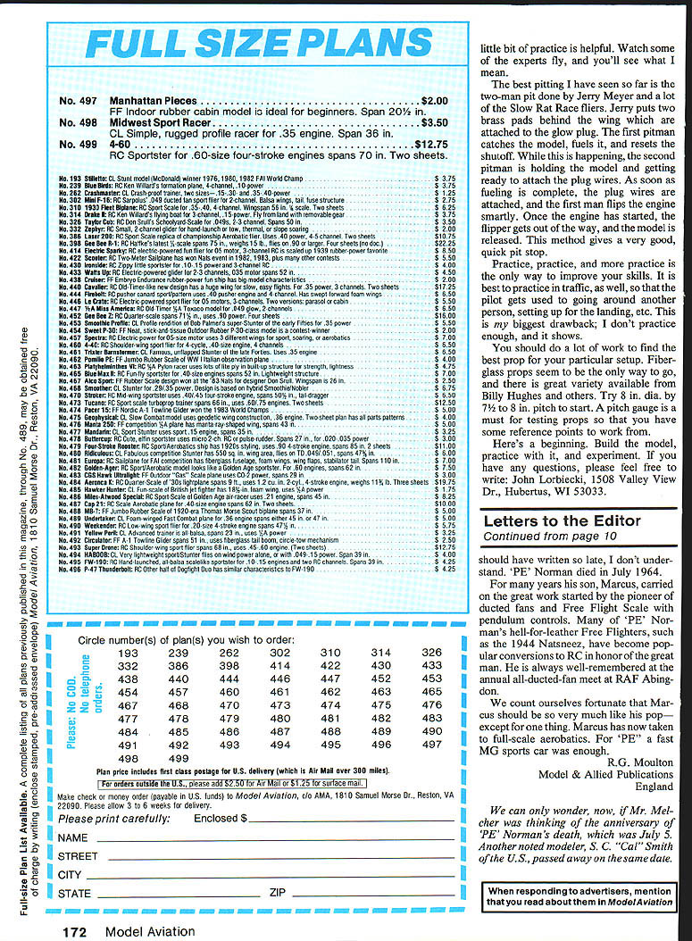
Midwest Sport Racer
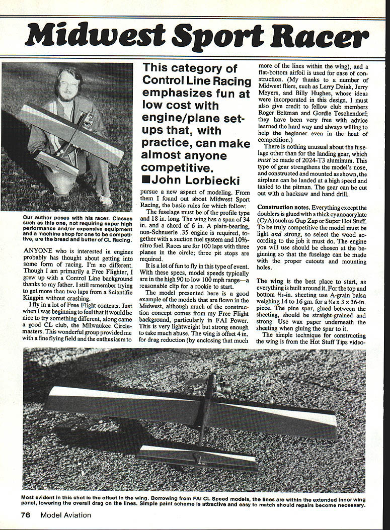
This category of Control Line racing emphasizes fun and low-cost engine/plane setups that, with practice, can make almost anyone competitive. The model and techniques described here are representative of Midwest Sport Racing and reflect ideas contributed by a number of Midwest fliers, including Larry Dziak, Jerry Meyers, Billy Hughes, Roger Beitman, and Gordie Teschendorf.
Rules (basic)
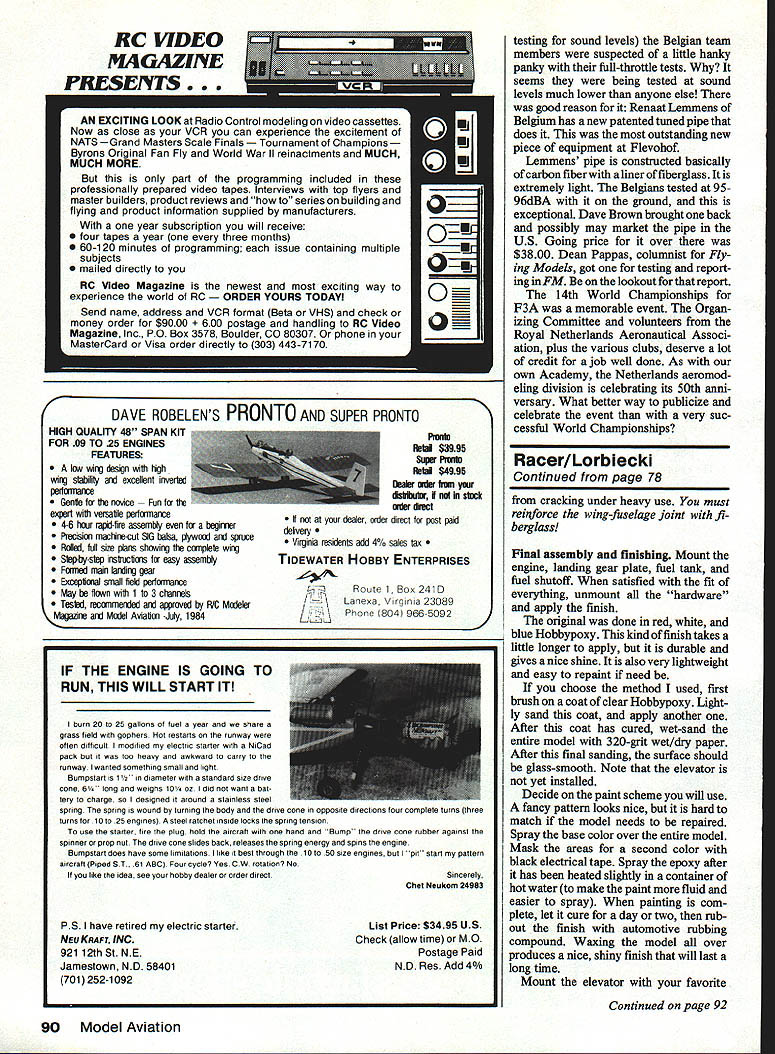
- Fuselage: profile type, 18 in. long.
- Wing: span 34 in., chord 6 in.
- Engine: production .35 plain-bearing, non‑Schnuerle (loop‑scavenged) required; all internal components stock.
- Fuel system: suction tank; 10% nitro fuel.
- Race format: 100 laps; three planes in the circle; three pit stops required.
Typical model speeds are high 90s to low 100 mph — a reasonable clip for a rookie.
Design overview
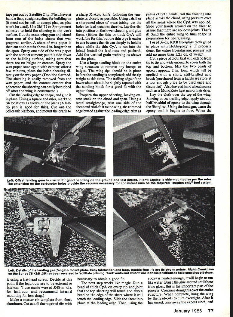
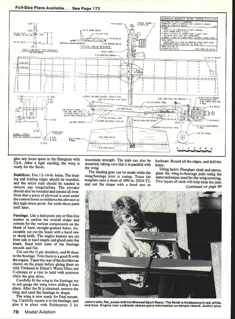
The model described is lightweight but strong, borrowing construction concepts from Free Flight (particularly FAI Power). The wing is offset 4 in. to enclose more of the lines within the wing and reduce drag. A flat‑bottom airfoil is used for ease of construction. The landing gear must be made from 2024‑T3 aluminum; this strengthens the nose so the airplane can be landed at high speed and taxied to the pitman. The gear can be cut out with a hacksaw and a hand drill.
Construction notes (general)
- Everything except the doublers is glued with a thick cyanoacrylate (CyA) such as Gap Zap or Super Hot Stuff.
- To be competitive, the model must be light and strong—select wood according to the job it must do.
- Choose the engine at the start so fuselage cutouts and mounting holes can be laid out correctly.
- The wing is the best place to start; everything is built around it.
Wing construction
Materials and preparation:
- Top and bottom sheeting: A‑grain balsa, 1/16 in. thick; cut to about 6 x 36 in. to match the wing chord and span.
- Spar: straight‑grained pine, glued between the sheeting.
- Use wax paper under the sheeting when gluing the spar.
Building surface and holding sheeting:
- Use a firm, straight surface for building.
- Use 3M 77 or Spraymount adhesive to hold the sheeting to the work surface.
- Cut a sheet of wax paper about 4 in. longer than the span; spray one side with contact cement and lay it down smooth on the work surface. Spray the exposed side of the wax paper and, after a few minutes, place the balsa sheeting onto it. The sheeting can be removed later and the cement residue rubbed off.
Assembling ribs and structure:
- Cut and glue the leading edge to shape.
- Using a square and ruler, mark rib locations as shown on the plans.
- Cut the bellcrank platform and fit the bellcrank; follow the template closely, trimming with a sharp X‑Acto knife where needed.
- Drill holes for lead‑outs through the ribs using a drill or sharpened brass tubing.
- Lay ribs into position on the lower sheeting and glue them. Thin CyA is easiest here because it wicks into joints while you hold parts in place.
- Install lead‑outs and the pushrod. Add vertical‑grain webbing as shown on the plans.
- Use a large sanding block to fair the entire wing structure; install wing tips and tip weight before finishing sanding.
- Taper the trailing edge of the lower sheeting slightly for a good fit with the upper sheeting.
Upper sheeting and bonding:
- Prepare the upper sheeting with excess at chord and span; trim to fit using a metal straightedge.
- Run a bead of thick CyA on every rib and joint that the top sheeting will touch and on the edge of the sheet where it meets the leading edge.
- Slide the sheet into place at the leading edge and roll the sheeting into position with the palms of both hands, applying pressure over all glued areas to ensure full bond.
- Sand the entire wing to final shape in preparation for fiberglassing.
Fiberglassing the wing
- Use 0.6‑oz fiberglass cloth and epoxy (Hobbypoxy 2 recommended).
- Cut a piece of cloth tip to tip, wide enough to cover top and bottom.
- Mix epoxy and apply with a short, stiff‑bristled acid brush.
- Lay the cloth over the wing. Starting at the trailing edge, apply epoxy through the cloth in small sections.
- Use a heat gun or hair dryer to warm the epoxy until it flows, then brush until the gloss disappears.
- Hang the wing by the lead‑outs to cure overnight.
- Trim excess cloth, glue loose spots with CyA, and lightly sand. Properly done, fiberglassing should add no more than about 1.25 oz. If desired, use two layers of cloth at the wing‑fuselage joint for extra strength.
Stabilizer and elevator
- Use 12–14‑lb balsa for the stabilizer (choose straight‑grained stock).
- Round the leading and trailing edges and sand the center stab to remove irregularities.
- Round and sand the elevator; reinforce the elevator at the control‑horn area with a piece of plywood.
- Set these parts aside until final assembly.
Fuselage
- Trace the overall shape and cutouts on a blank of hard, straight‑grained balsa using a ball‑point pen or fine‑line marker.
- Cut the blank accurately with a bandsaw or sharp knife. Sand both sides smooth and fair.
- Cut engine bearers from oak or hard maple and glue them onto the blank.
- Cut 1/8‑in. plywood doublers, fit them to the fuselage, and trim for a good fit with the engine. Taper the rear of the doublers as shown on the plans.
- Glue doublers with Titebond or Elmer's Wood Glue and clamp with C‑clamps or a vise while drying.
Wing fitting and mounting:
- Carefully fit the wing to the fuselage without gouging the wing. Remove the wing and sand the fuselage to shape as required.
- Square the wing to the fuselage and glue it in place with Hobbypoxy 2 for maximum strength.
- Mount the stabilizer, ensuring it is parallel to the wing.
Landing gear
- Trace the template onto .090‑in. 2024‑T3 aluminum sheet and cut the shape with a bandsaw or hacksaw.
- Round all edges and drill mounting holes as shown on the plans.
- Attach the gear plate as part of final assembly.
Reinforcing the wing‑to‑fuselage joint
- Reinforce the joint with heavy fiberglass cloth and epoxy, using the same technique as the wing covering.
- Two layers of cloth are recommended to prevent cracking under heavy use.
Final assembly and finishing
- Mount the engine, landing gear plate, fuel tank, and fuel shutoff. Verify fit, then unmount hardware for finishing.
- Finish: Hobbypoxy been used with good results. Brush on a clear coat, sand lightly, apply another coat, then wet‑sand with 320‑grit wet/dry paper until glass‑smooth.
- Paint: spray the base color, mask areas for additional colors with black electrical tape, and spray the epoxy after warming it in hot water for better flow. Let cure, then rub out with automotive rubbing compound and wax for a durable shine.
- Reinstall hardware: mount elevator with preferred hinges (Klett hinges work well), install control horns (one for flight control, one for the fuel shutoff), hook up pushrod and shutoff linkage. The shutoff should activate with full‑down elevator and snap firmly.
- Mount engine, tank, tail and wing skids. The model is then ready to fly.
Engine selection and preparation
- Rules require a production .35, plain‑bearing, loop‑scavenged engine (K&B .35 Series 75 and Super Tigre .35C plain bearing were common).
- A stock unit is a good starting point; a few tuning steps help for racing:
Piston ring and liner:
- Fit piston ring to liner by sliding the ring in and inspecting for light leaks; find a set with no light visible around the ring.
- Check ring end gap with a feeler gauge: target .002–.004 in. If greater, the ring will not seat; if less, file to the proper gap.
- Relieve (choke) the lower part of the liner about 0.25 in. above the exhaust port to reduce ring drag. Use an automotive brake hone with light oil, stroking slowly; remove only about .0015–.0025 in. total. Clean all parts thoroughly after honing.
Crankshaft/intake timing:
- Reworking the crank to change intake timing to close at 62° after top dead center (TDC) can increase power. This requires a 360° protractor, a vise, a pointer (music wire), and a mechanical stop. Mount the protractor on the crank and use the pointer on an engine lug to time accurately.
Glow plugs:
- Short glow‑plug life can be a problem; one solution is to raise the head .004 in. at a time to reduce damage. The K&B Long plug has provided good runs for many.
Fuel system and needle setup
- The suction tank system and venturi selection are critical. A larger venturi hole gives more power but can cause fuel‑draw problems.
- Spraybar: enlarge the hole to approximately .055 in. diameter and position it about .15 in. below the lip of the venturi (manometer tests showed maximum draw at this position).
- Favorable venturi: extends about .6 in. out of the housing, with the needle valve centered about .2 in. above the housing. A central hole of about .343 in. diameter with a machined venturi shape has worked well.
- Fuel tank location is critical: as little as .12 in. up or down can change whether the engine runs consistently or goes rich at the start and lean at the end. Experimentation is necessary.
Assembly and break‑in:
- Assemble the engine carefully and keep parts clean. The engine should flip over smartly. If the ring leaks, try running the engine for some time to seat the ring before replacing it; some rings require fuel and running to seat properly.
- Test with an 8‑8 Rev‑Up prop initially; aim for something around 16,000 rpm in test runs.
Flying and operating tips
- Cut a set of lines to match the airplane. Test‑run the engine and exercise the shutoff several times before flying.
- Always fill the tank for each takeoff; with the feed line as far forward as it is, the engine may stop before leaving the ground if the tank isn’t full.
- If the engine runs rich, have the pilot fly a little high to see if it leans out. If it runs lean, shut it off and richen the needle setting before the ring seal is damaged.
- On each landing, practice catching the model and restarting it; every flight teaches trimming and engine behavior.
- Practice in traffic so the pilot becomes comfortable flying around other people and setting up landings.
Pitting technique
- The two‑man pit is highly effective: one pitman catches the model, fuels it, and resets the shutoff while the second pitman holds the model, attaches plug wires, and prepares to release. Jerry Meyer and many Slow Rat Race fliers use brass pads behind the wing attached to the glow plug to ease plug hookup. This method yields quick, reliable pit stops.
Propellers
- Spend time finding the best prop for your setup. Fiberglass props are recommended. Try 8 in. diameter by 7.5 in. pitch as a starting point.
- A pitch gauge is essential for testing props and developing reference points.
Final advice
Build the model, practice with it, and experiment with engine and fuel system settings. Watch experienced fliers, practice pitting and flying in traffic, and expect to learn from every flight.
If you have questions, write to: John Lorbiecki 1508 Valley View Dr. Hubertus, WI 53033
Transcribed from original scans by AI. Minor OCR errors may remain.

