
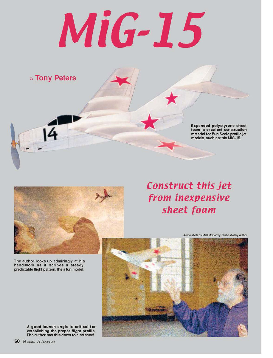

MiG-15: Construct this jet from inexpensive sheet foam
by Tony Peters
I love building model airplanes. There is something wonderful about turning a flat drawing and bits of wood and tissue into a three-dimensional sculpture that magically flies through the air. For years I churned out model after model, hanging them wingtip-to-wingtip in my summer home and in my son's bedroom. Now that I am more or less retired, I have little time to build. Those of you on the working side of Social Security will scoff at this—I know I did—but most of my aging peers are probably nodding in agreement.
Some time ago a neighbor—a retired building contractor—asked me how I liked being retired and whether or not I was making lots of new models. I told him how busy I was and how the days seemed to slip like sand through my fingers, leaving me little time to build. He thought about that for a moment. "Put on more men," he advised me. This has become my geriatric cohort's motto, but there is a better solution to the embarrassment and boredom of showing up week after week with the same tired models: a foam profile model.
These models have advantages beyond quick and easy construction: they are cheap; they're sturdy (my MiG has survived countless collisions with walls and table legs, was knocked out of the grasp of trees with a wildly flailing pole, and even spent a rainy week in a tree as it worked its way down to where I could get at it); and last but not least, they look really neat.
Construction
Materials and supplies
- Sheet foam (sources recommended: Aerospace Composites, Kenway Microflight, Peck-Polymers). Disposable foam dinner plates, take-out food containers, or trays can also be used and butt-joint-glued together.
- Tyvek (plastic-reinforced paper; commonly available as FedEx/Express Mail envelopes).
- Water-based white glues or solvent-based glues suitable for foam (test on scrap first).
- Water-based acrylic clear varnish for decorations (test first).
- X-Acto or razor blade.
- Balsa: nose block and motorstick.
- Hard balsa 1/16 x 1/4 inch for motorstick.
- Wire for rear motor mount, thin plastic for radio mast.
- Clear-plastic cup for propeller blades, tubing or hardwood for prop shaft lining.
- Non-water-based felt-tip pen for panel lines and details.
- Black Contact paper for numbers and canopy (or similar self-adhesive sheet).
Preparing the foam and glue notes
- Many inexpensive foam alternatives are too small for a whole wing or fuselage; butt-joint and strengthen joints with a glue skin and optional Tyvek reinforcement.
- Tyvek can be cut with a razor or scissors (it does not tear cleanly). Split with a razor and glue fuzzy-side down.
- For gluing foam, use water-based white glues or compatible solvent glues (Goo-Loo, Duco, etc.). Always test adhesives on scrap.
- I use a water-based acrylic varnish to attach decorations such as red tissue-paper stars.
Cutting and basic assembly
- Cut the parts from the plan. The fuselage and the lower half of the vertical fin are one piece; you only need one wing. Omit the wing fences if desired.
- Cut two small square holes in each pattern and use them to tape the pattern to the foam.
- Use thicker foam (about 2 mm) for the fuselage and wing; use thinner foam (about 1 mm) for the tail and fences.
- Cut out the foam with a new X-Acto or razor blade. After cutting the fuselage outline, cut the wing-mount space and the fuselage airfoil.
- The first 5/8 inch of the nose is balsa to match the thickness of the fuselage foam. Glue the balsa nose to the foam and round all the edges for a finished look.
- The motorstick is 1/16 x 1/4-inch hard balsa and runs from the nose to the rear of the fuselage.
- The motor mount is a sandwich of three bits of 1/16-inch balsa. The rear motor mount is a loop of wire sandwiched between the motor mount and a bit of 1/16-inch balsa, and secured with Tyvek. Glue the motor mount onto the fuselage between the marks on the plan.
- Note: I mounted my motorstick on the right side because I'm right-handed and prefer not to see it when I hold the model up. Mount it wherever pleases you.
Skin and gluing
- The plastic skin on sheet foam imparts much of the strength. To get a good glue joint, sand it lightly where the motorstick attaches to the fuselage and where the horizontal stabilizer sits on the fin.
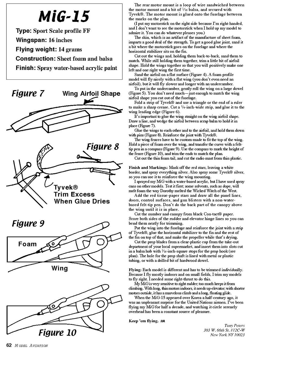
- Glue the wings to each other and to the fuselage airfoil; hold with pins and reinforce the joint with Tyvek.
Wings and airfoil
- Cut out the wings and, holding them back-to-back, sand them to match. While still holding them together, trim a little airfoil shape. This ensures you make one true left and one true right wing the first time.
- Sand the airfoil on a flat surface. A flat wing will fly, but an undercamber makes it fly slower and longer.
- To add undercamber, gently roll the wing on a large dowel—only a little is needed to match the fuselage airfoil.
- Fold a strip of Tyvek and crease it sharply with a triangle or the end of a ruler. Cut a 1/4-inch-wide strip and glue it to the wing leading edge.
- Draw a center line for alignment and wedge the airfoil between scrap balsa to hold it in place while gluing.
Wing fences
- The wing fences must be custom-fit to the top of the wing. Hold a piece of thin foam over the wing and transfer the curve with a felt-tip pen in a compass. Use the compass to mark the fence height and trim the ends to match the plan.
Tail and radio mast
- Cut out the thin-foam tail pieces and cut the radio mast from thin plastic.
- Score both sides of the rudder and elevator hinge lines so you can bend them neatly for trimming and to make them movable.
Finish and markings
- Mask off the red stars, leaving a white border, and spray the model silver. Also spray some Tyvek silver for use as reinforcement at the wing mounting.
- I used a water-based acrylic spray; avoid solvent dopes that can melt foam. Test any finish first.
- Add red tissue-paper stars and draw panel lines, doors, control surfaces, and gun blisters with a non-water-based felt-tip pen. Do not do the rear part of the canopy above the wing until the wing is installed.
- Cut the number and canopy shapes from black Contact paper (or similar) and apply.
Propeller and hub
- Cut propeller blades from a clear-plastic cup (take-out department). Insert blades into slots cut in a balsa hub, with 1/16-inch-square stops for the prop hook (see plan).
- Line the prop shaft hole with metal or plastic tubing or a drilled bit of hardwood dowel.
Flying and trimming
- Each model must be trimmed individually. I fly mostly indoors and on small fields, so I trim my models to fly right and typically add some right-thrust.
- My MiG is very sensitive to right rudder; too much right rudder prevents it from climbing. With long, thin motors (indoors) it needs up-elevator; with shorter motors (outdoors) it gives a marvelous climb and a long, floating glide.
When the MiG-15 appeared over Korea a half-century ago, it was an unpleasant surprise for United Nations airmen. I've been flying my MiG for half a decade, and watching it circle serenely overhead has been a constant source of pleasure.
Keep 'em flying.
Tony Peters 303 W. 66th St. 11-2C-W New York, NY 10023
Plan notes and dimensions
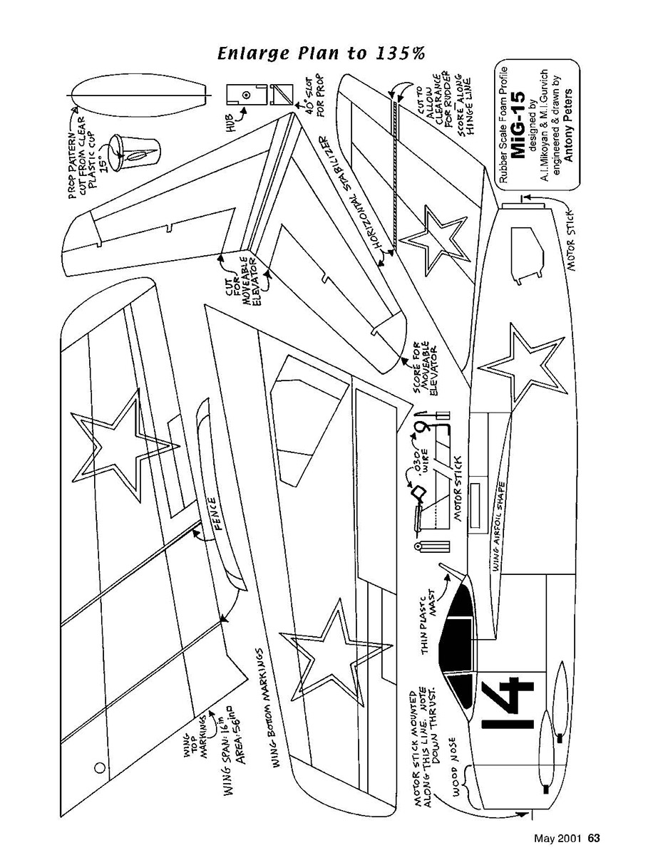
- Enlarge plan to 135%
- Prop pattern cut from plastic cup — 15°
- Hub
- 40° slot for prop
- Horizontal stabilizer
- Cut to allow clearance for prop rod; score along hinge line
- Cut movable elevator
- Score for hingable elevator
- Fence
- Wing bottom markings
- Wing span: 18 in.; Area: 56 sq. in.
- Thin plastic mask
- Wing airfoil shape
- Motor stick
- Motor stick mounted along this line to allow down-thrust
- Wood nose
Rubber Scale Foam Profile MiG-15 A. I. Mikoyan & Gurevich Designed & drawn by Anthony Peters
Transcribed from original scans by AI. Minor OCR errors may remain.

