
MiG-29 Catapult Glider
Dennis O. Norman
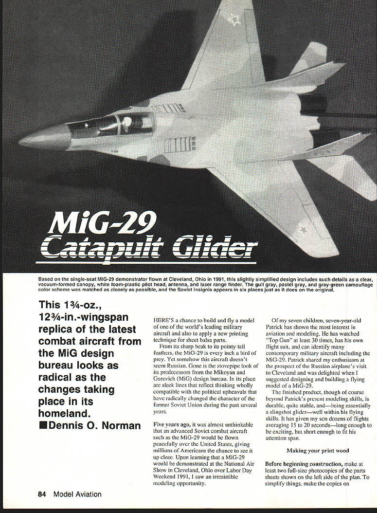
This 1 3/4-oz., 12 3/4-in. wingspan replica of the latest combat aircraft from the MiG design bureau looks as radical as the changes taking place in its homeland.
HERE'S a chance to build and fly a model of one of the world's leading military aircraft and also to apply a new printing technique for sheet balsa parts.
From its sharp beak to its pointy tail feathers, the MiG-29 is every inch a bird of prey. Yet somehow this aircraft doesn't seem Russian. Gone is the stovepipe look of its predecessors from the Mikoyan and Gurevich (MiG) design bureau. In its place are sleek lines that reflect thinking wholly compatible with the political upheavals that have radically changed the character of the former Soviet Union during the past several years.
Five years ago, it was almost unthinkable that an advanced Soviet combat aircraft such as the MiG-29 would be flown peacefully over the United States, giving millions of Americans the chance to see it up close. Upon learning that a MiG-29 would be demonstrated at the National Air Show in Cleveland, Ohio over Labor Day weekend 1991, I saw an irresistible modeling opportunity.
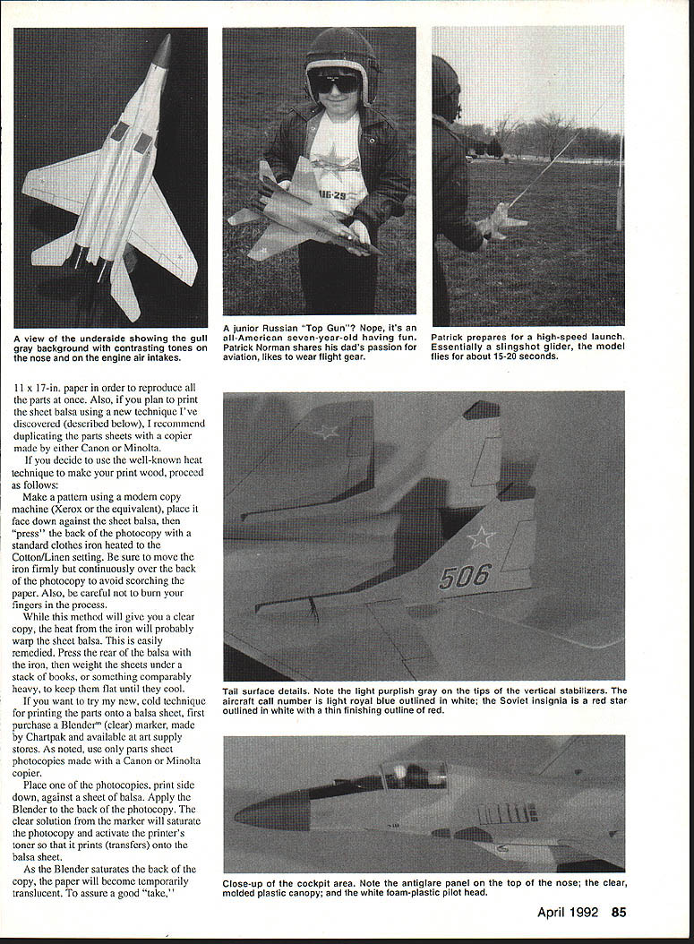
Of my seven children, seven-year-old Patrick has shown the most interest in aviation and modeling. He has watched "Top Gun" at least 30 times, has his own flight suit, and can identify many contemporary military aircraft including the MiG-29. Patrick shared my enthusiasm at the prospect of the Russian airplane's visit to Cleveland and was delighted when I suggested designing and building a flying model of a MiG-29.
The finished product, though of course beyond Patrick's present modeling skills, is durable, quite stable, and—being essentially a slingshot glider—well within his flying skills. It has given my son dozens of flights averaging 15 to 20 seconds—long enough to be exciting, but short enough to fit his attention span.
Making your print wood
Before beginning construction, make at least two full-size photocopies of the parts sheets shown on the left side of the plan. To simplify things, make the copies on 11 x 17-in. paper. Also plan to print sheet balsa using a technique described below. I recommend duplicating parts sheets on a copier made either by Canon or Minolta.
Heat-transfer technique (iron)
If you decide to use the well-known heat-transfer technique to make print wood, proceed as follows:
- Make a pattern using a modern copy machine (Xerox equivalent).
- Place the copy face down against the sheet balsa.
- Press the back photocopy with a standard clothes iron heated to the Cotton/Linen setting.
- Move the iron firmly and continuously over the back photocopy to avoid scorching the paper. Be careful not to burn your fingers.
- After transferring, the heat will probably warp the sheet balsa. Press the balsa under a stack of books or something comparably heavy until cool to keep it flat.
This method will give a clear copy but has the hazard of a hot iron and possible warping.
Cold-transfer technique (Blender marker)
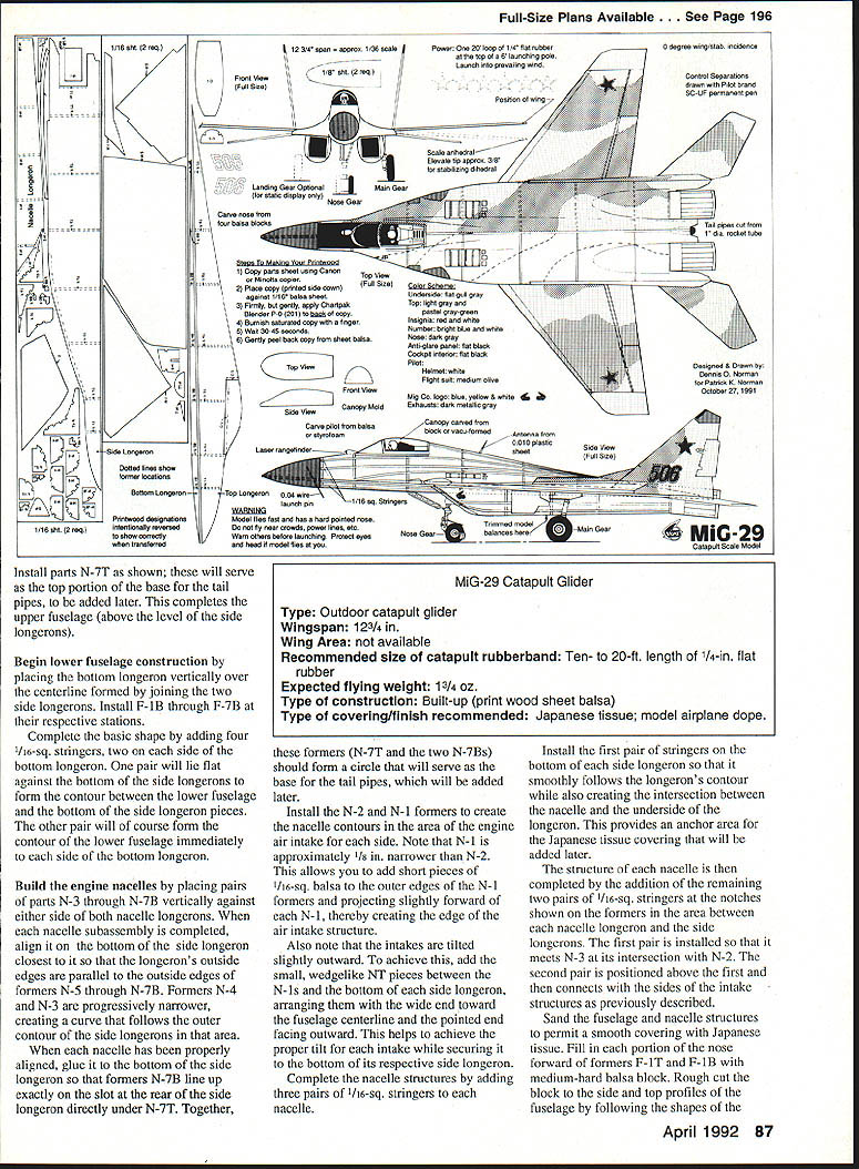
If you want to try a cold technique for printing parts onto balsa, first purchase a Blender™ (clear) marker, made by Chartpak and available at art-supply stores. Use only parts-sheet photocopies made with a Canon or Minolta copier.
Procedure:
- Place one of the photocopies, print side down, against a sheet of balsa.
- Apply the Blender to the back of the photocopy. The clear solution will saturate the copy and activate the printer's toner so that it transfers onto the balsa.
- As the Blender saturates the paper, the copy will become temporarily translucent. Rub the saturated paper firmly with your finger to burnish the transfer.
- Allow 30–45 seconds for the paper to lose some moisture before gently peeling it away from the balsa.
- As you peel, hold the transferred part firmly in place and check the transfer. If any portion is light or incomplete, lay the paper back down and reapply the Blender over the poorly printed portions, let it set, and try again.
This cold technique avoids the hazards of a hot iron and the hassle of warped balsa sheets.
Construction
Begin construction by joining the side longerons at their centerlines. Note that locations of the top fuselage formers appear on the top left side of the longerons (and on the bottom right side) as guides to placement.
- Install the top longeron directly over the centerline of the joined side longerons to form the basic "keels" for the upper fuselage. Add formers F-1T through F-4T.
- Assemble each half of the wing by joining parts W-1 and W-2 so that the flattened tip of W-1 is at the centerline facing forward.
Although the MiG-29 wing has an anhedral (droop), the model has dihedral for greater stability. To set the dihedral:
- Place a 1/16-sq. balsa strip beneath each wing half at its intersection with the side longeron.
- Press the centerline of each wing half flat into the joint of the top and side longeron; this elevates the tip of each wing half approximately 3/8 in. This contributes to excellent flight characteristics without radically changing appearance.
Once the wing halves are joined to the fuselage, install F-5T through F-7T. Complete the basic contour of the fuselage top by adding 1/16-in. stringers as shown on the plan. If stringers misalign slightly after notching, widen or narrow the spacing until contours are smooth and flowing.
Add the long, curved F-ws to either side of the forward portions of the side longerons to fair them into the wing contour. Install C-1 and C-2 to define the cockpit area.
Install parts N-7T as shown; these will serve as the top portion of the base for the tail pipes to be added later. This completes the upper fuselage (above the level of the side longerons).
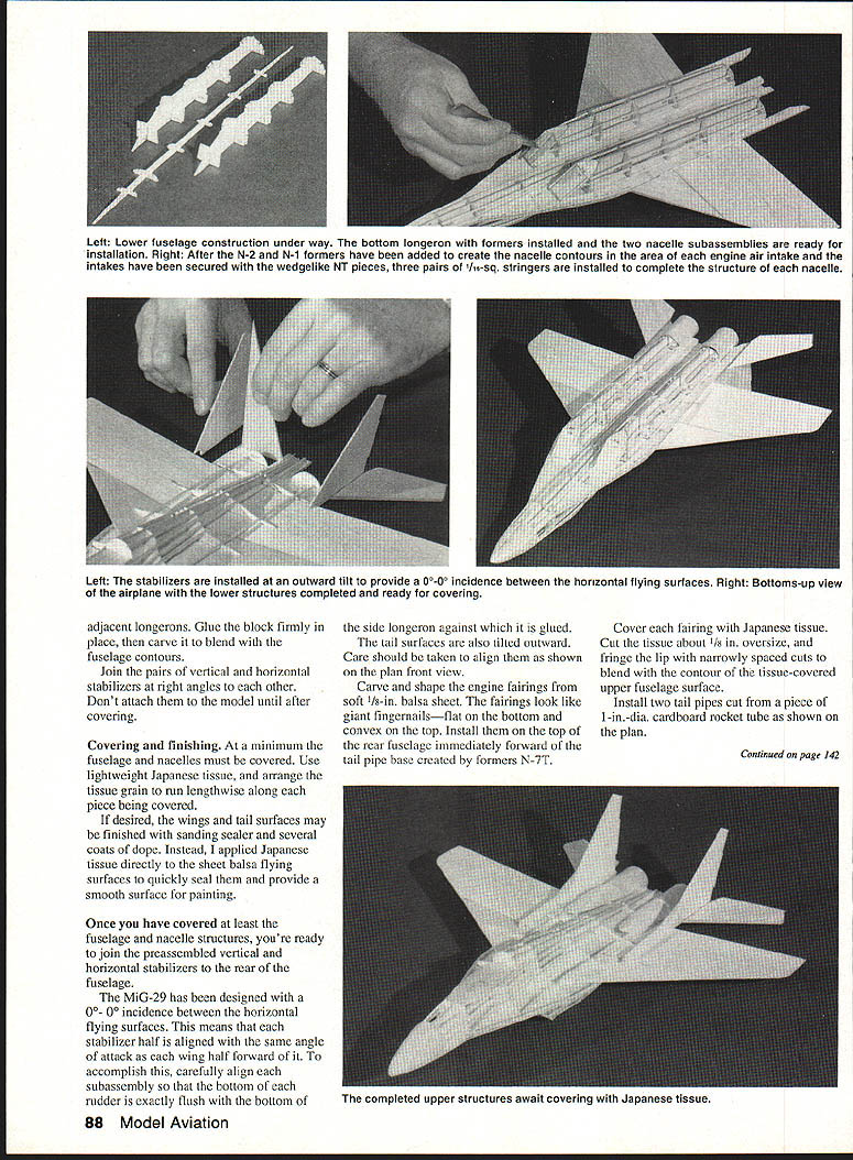
Begin lower fuselage construction by placing the bottom longeron vertically over the centerline formed by joining the two side longerons. Install F-1B through F-7B at their respective stations.
Complete the basic lower shape by adding four 1/16-sq. stringers, two on each side of the bottom longeron:
- One pair lies flat against the bottom of the side longerons to form the contour between the lower fuselage and the bottom of the side longeron pieces.
- The other pair forms the contour of the lower fuselage immediately to each side of the bottom longeron.
Engine nacelles
Build the engine nacelles by placing pairs of parts N-3 through N-7B vertically against either side of both nacelle longerons. When each nacelle subassembly is completed:
- Align it on the bottom of the nearest side longeron so that the longeron's outside edges are parallel to the outside edges of formers N-5 through N-7B.
- Note that formers N-4 and N-3 are progressively narrower, creating a curve that follows the outer contour of the side longerons.
Glue each nacelle to the bottom of the side longeron so that formers N-7B line up exactly on the slot at the rear of the side longeron directly under N-7T. Together, N-7T and the two N-7Bs should form a circle that will serve as the base for the tail pipes, added later.
Install N-2 and N-1 formers to create nacelle contours in the area of the engine air intake for each side. Note that N-1 is approximately 1/8 in. narrower than N-2. Add short pieces of 1/16-sq. balsa to the outer edges of N-1, projecting slightly forward of each N-1, thereby creating the intake lip and intake structure.
The intakes are tilted slightly outward. To achieve this:
- Add the small, wedge-like N-T pieces between the N-1s and the bottom of each side longeron, arranging them with the wide end toward the fuselage centerline and the pointed end facing outward.
- This helps achieve the proper tilt for each intake while securing it to the bottom of its respective side longeron.
Complete each nacelle by adding three pairs of 1/16-sq. stringers:
- Install the first pair on the bottom of each side longeron so it smoothly follows the longeron's contour and forms the intersection between the nacelle and the underside of the wing longeron. This provides an anchor area for the Japanese tissue covering.
- Add the remaining two pairs at the notches shown on the formers in the area between each nacelle longeron and the side longeron. The first pair meets N-3 at its intersection with N-2; the second pair sits above the first and connects with the sides of the intake structures.
Sand the fuselage and nacelle structures to permit a smooth covering with Japanese tissue.
Nose and cockpit
Fill each portion of the nose forward of formers F-1T and F-1B with medium-hard balsa block. Rough-cut the block to the side and top profiles of the fuselage by following the shapes on the plan. Glue the block firmly in place, then carve and sand to the final contour to blend with the fuselage.
Complete the cockpit area by installing the canopy mold and cockpit details as shown on the plan. The canopy may be carved from block or vacuformed; if carving, burnish and sand to fit the opening. Install the pilot's head and other cockpit details, and fair the canopy into the fuselage contours with thin balsa strips where necessary.
Tail assembly and stabilizers
Join the pairs of vertical and horizontal stabilizers at right angles to each other but do not attach them to the model until after covering.
The MiG-29 model is designed with 0°-0° incidence between the horizontal flying surfaces; each stabilizer half is aligned with the same angle of attack as the corresponding wing half forward of it. Carefully align each subassembly so the bottom of each rudder is exactly flush with the bottom of the side longeron against which it is glued.
The tail surfaces are also tilted outward—align them as shown on the plan front view.
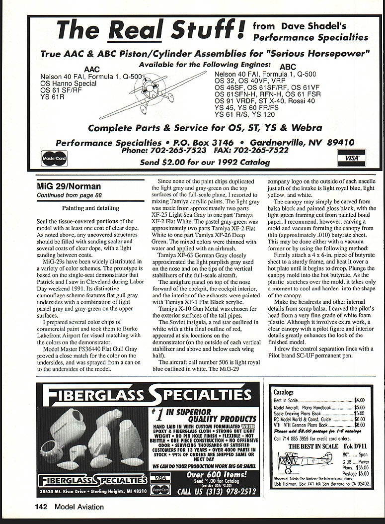
Engine fairings and tail pipes
Carve and shape the engine fairings from soft 1/8-in. balsa sheet. The fairings are flat on the bottom and convex on top. Install them on the top of the rear fuselage immediately forward of the tail-pipe base created by formers N-7T.
Cover each fairing with Japanese tissue. Cut the tissue about 1/8 in. oversize, and fringe the lip with narrowly spaced cuts to blend with the contour of the tissue-covered upper fuselage surface.
Install two tail pipes cut from a piece of 1-in.-dia. cardboard rocket tube as shown on the plan.
Covering and finishing
At a minimum, cover the fuselage and nacelles with lightweight Japanese tissue. Arrange the tissue grain to run lengthwise along each piece being covered.
If desired, the wings and tail surfaces may be finished with sanding sealer and several coats of dope. Alternatively, apply Japanese tissue directly to the sheet balsa flying surfaces to quickly seal them and provide a smooth surface for painting.
Once you have covered at least the fuselage and nacelles, join the preassembled vertical and horizontal stabilizers to the rear of the fuselage.
Details and omissions
- The characteristic laser range finder was carved from scrap balsa. The housing is flat black; the front portion is flat aluminum.
- The antenna, located on the top of the fuselage aft of the cockpit, was cut from .010-in. butyrate sheet.
- For simplification, details such as the Pitot tube on the tip of the nose and various small protuberances from the flying surfaces were omitted.
- No landing gear is included; the prototype was designed for vigorous high-speed flights that typically end with a landing on grass or weeds. If you want landing gear for display, use a plastic MiG-29 kit as a reference. The approximate size and location of the gear are included on the plan.
Specifications
- Type: Outdoor catapult glider
- Wingspan: 12 3/4 in.
- Wing area: Not available
- Recommended catapult rubber: 10- to 20-ft. length of 1/4-in. flat rubber
- Expected flying weight: 1 3/4 oz.
- Type of construction: Built-up (print wood sheet balsa)
- Covering/finish recommended: Japanese tissue; model airplane dope
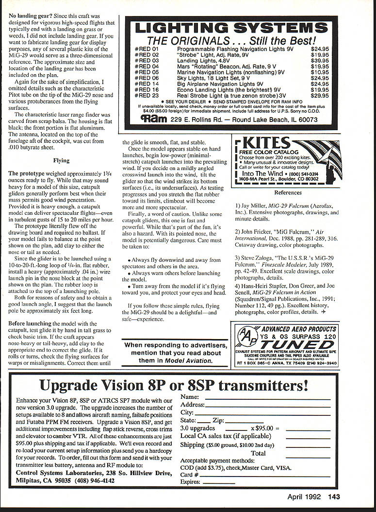
Painting and detailing
Seal the tissue-covered portions of the model with at least one coat of clear dope. Any uncovered structures should be filled with sanding sealer and given several coats of clear dope, with light sanding between coats.
The prototype demonstrator seen in Cleveland during Labor Day weekend 1991 features:
- Flat gull gray undersides (Model Master FS36440 Flat Gull Gray was a close match; sprayed from a can).
- Upper surfaces with a combination of light pastel gray and gray-green. These were mixed from Tamiya acrylics:
- Light gray: approx. 2 parts XF-25 Light Sea Gray to 1 part XF-2 Flat White.
- Pastel gray-green: approx. 2 parts XF-2 Flat White to 1 part XF-26 Deep Green.
- Thin with water and apply with an airbrush.
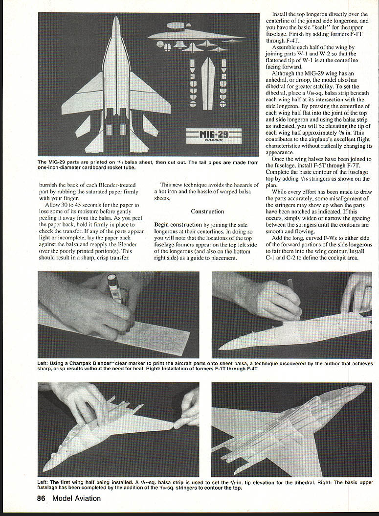
- Tamiya XF-63 German Gray approximated the light purplish gray on the nose and vertical-stabilizer tips.
- Antiglare panel on top of the nose forward of the cockpit, cockpit interior, and exhaust interiors: Tamiya XF-1 Flat Black.
- Tail pipe exterior: Tamiya X-10 Gun Metal.
Markings:
- Soviet insignia: red star outlined in white with a thin final outline of red; appeared at six locations (outside of each vertical stabilizer and above and below each wing half).
- Aircraft call number 506: light royal blue outlined in white.
- MiG-29 company logo on each nacelle just aft of the intake: light royal blue, light yellow, and white.
Canopy:
- The canopy may be carved from balsa and painted gloss black, with the light green framing cut from painted balsa paper.
- Recommended: carve a complete mold and vacuum form the canopy from thin (~.010 in.) butyrate sheet. One method: attach a 4 x 6-in. piece of butyrate to a sturdy frame, heat it over a hot plate until it droops, then plunge the hot plastic over the hot mold. As the plastic stretches, it will thin and harden into the canopy shape.
- Make headrests and internal details from scrap balsa. A pilot figure and interior details greatly enhance the model.
- Draw control separation lines with a Pilot SC-UIF permanent pen.
Flying
The prototype weighed approximately 1 3/4 oz. ready to fly. Catapult gliders generally perform best when heavy enough for good wind penetration. Provided it is heavy enough, a catapult model can deliver spectacular flights—even in turbulent gusts of 15 to 20 mph.
- Balance: The prototype flew without ballast. If your model fails to balance at the point shown on the plan, add clay to the nose or tail as needed.
- Launch pin: Install a heavy (~.040-in.) wire launch pin in the nose block at the point shown on the plan. The rubber loop attaches to the loop of a launching pole.
- Launch pole: For safety and to obtain a good launch angle, use a launching pole approximately six feet long.
- Test glide: Before catapult launching, test-glide by hand in tall grass to check basic trim. Add clay if nose- or tail-heavy. Correct any roll or turn by fixing warps or misalignments.
- Catapult launches: Begin with low-power (minimal-stretch) launches into the prevailing wind. For a mildly angled crosswind launch into the wind, tilt the glider so that the wind strikes its undersurfaces. As you stretch the flat rubber more, climbout will become more spectacular.
Safety precautions—this model is fast and powerful and has a pointed nose:
- Always fly downwind and away from spectators and others in the area.
- Always warn others before launching the model.
- If the model is flying toward you, turn away and protect your eyes and head.
If you follow these rules, flying the MiG-29 should be a delightful—and safe—experience.
References
- Jay Miller, MiG-29 Fulcrum (Aerofax, Inc.). Extensive photographs, drawings, and minute details.
- John Fricker, "MiG Fulcrum," Air International, Dec. 1988, pp. 281–289, 316. Cutaway drawing, color photographs.
- Steve Zaloga, "The U.S.S.R.'s MiG-29 Fulcrum," FineScale Modeler, July 1989, pp. 42–49. Excellent scale drawings, color photographs, details.
- Hans-Heiri Stapfer, Don Greer, and Joe Snell, MiG-29 Fulcrum in Action (Squadron/Signal Publications, Inc., 1991; Number 112, 49 pp.). Excellent history, photographs, color profiles, details.
Transcribed from original scans by AI. Minor OCR errors may remain.

