
MiG Sweeper
Windy Urtnowski
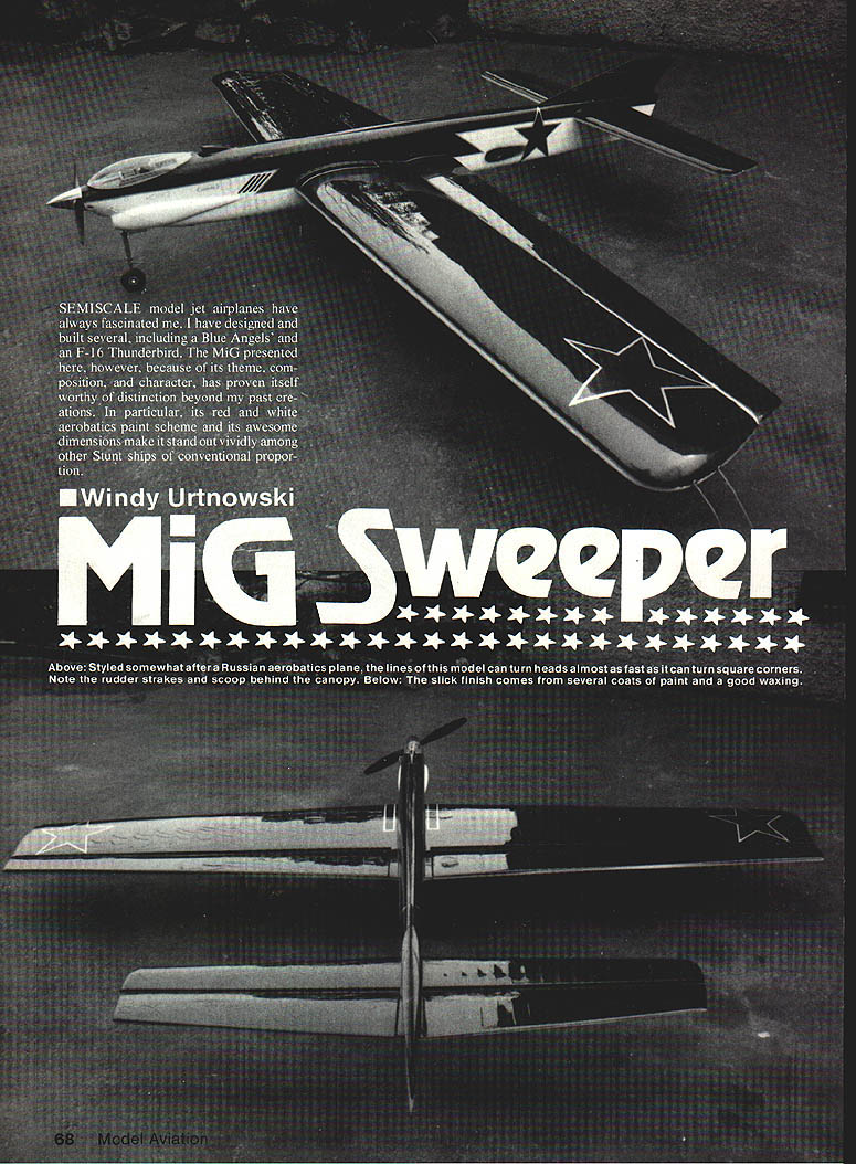
SEMISCALE model jet airplanes have always fascinated me. I have designed and built several, including a Blue Angels and an F-16 Thunderbee. The MiG presented here, however, because of its theme, composition, and character, has proven itself worthy of distinction beyond my past creations. In particular, its red-and-white aerobatics paint scheme and its awesome dimensions make it stand out vividly among other Stunt ships of conventional proportion.
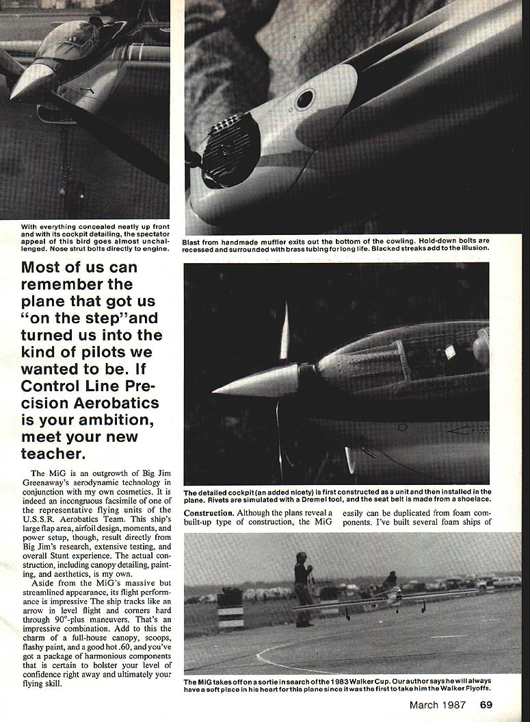
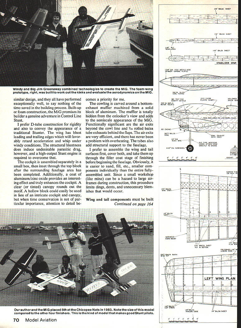
The MiG is an outgrowth of Big Jim Greenaway's aerodynamic technology in conjunction with my own cosmetics. It is an incongruous facsimile of a representative flying unit of the U.S.S.R. Aerobatics Team. This ship's large flap area, airfoil design, moments, and power setup result directly from Big Jim's research, extensive testing, and overall Stunt experience. The actual construction, including canopy detailing, painting, and aesthetics, is my own.
Aside from the MiG's massive but streamlined appearance, its flight performance is impressive. The ship tracks like an arrow in level flight and corners hard through 90°-plus maneuvers. That's an impressive combination. Add to this the charm of a full-house canopy, scoops, flashy paint, and a good hot .60, and you've got a package of harmonious components that will boost your confidence and ultimately your flying skill.
Construction
Although the plans reveal a built-up type of construction, the MiG can easily be duplicated from foam components. I’ve built several foam ships. Built-up or foam construction, the MiG promises its builder a genuine adventure. Control-line Stunt fliers prefer D-tube construction for rigidity; it also conveys the appearance of a traditional Stunter wing.
The traditional Stunter wing, with blunt leading and trailing edges, will favorably retard acceleration and reduce whip under windy conditions. Structural bluntness does induce undesirable parasitic drag, however, so a high-output Stunt engine is required to overcome it.
Assemble the cockpit separately: inset a small box through the top block after the surrounding fuselage area has been completed. A coat of aluminum/zinc-oxide provides an interesting effect and enhances the cockpit; a clear-tinted canopy rounds out the motif. For time conservation, a hollow block can be used in lieu of an intricate canopy, but then attention to detail in other areas becomes a priority.
The cowling is carved around the bottom-exhaust muffler. The machined solid-block-aluminum muffler is hidden from view and adds a semi-scale appearance. Functionally significant air exits beyond the cowl line are 1/16" rolled-balsa-tube exhausts behind the flaps. These exits are very efficient and have never given me overheating problems. The tubes also add structural support to the fuselage.
I prefer to assemble the wing and tail surfaces first, cover both, and take them through the filler/coat stage of finishing before beginning the fuselage. It’s easier to sand and fill smaller components individually than the entire assembled unit. In a small workshop this procedure limits dings, dents, and unnecessary blemishes.
Wing and tail
A flat building surface is imperative. I cover my work area with a sheet of 1/8-in. plate glass shimmed perfectly flat with computer card stock or ordinary playing cards. Place the plans under the glass so they are visible and the surface remains free from residual glue and debris. The glass is resilient to glue and cleans up nicely.
Gather enough 1 x 3 x 36-in. balsa planks to build box perimeters in which the wing, flaps, stab, and elevators will be constructed. Use a straightedge and strip the top and bottom edges of the planks to ensure straightness. Scribe a line 1/2 in. in from the bottom edges of each plank to serve as a guideline for the leading and trailing edges and end ribs.
Build box perimeters for:
- the wing,
- the stab,
- the flaps (both flaps can be built from the same box),
- the elevator (both elevators can be built from the same box).
My preferred sequence is wing first, then stab, and finally flaps and elevators, but the order is a matter of preference.
Construction steps:
- Tape-glue the appropriate top of the work surface and tack-glue the leading and trailing edges, ribs, and hard balsa spars (where applicable) in place.
- Apply sheeting and cap strips to all top surfaces.
- Carefully cut the box free of the glass, flip it over, and tack-glue it in place again.
- Repeat for the bottom surfaces, rechecking all centerlines before sheeting and cap stripping. (For the wing, install the bellcrank assembly before sheeting the bottom.)
- Carefully cut the box away from the completed assembly, block-sand where necessary, shape and hollow the tips, temporarily install hinges, and work in the filler coat in preparation for covering.
This procedure produces very straight and accurate wing and stab surfaces and is faster and easier than it may appear.
Fuselage
Use matched sides of moderately dense balsa with straight grain. Install plywood doublers, engine mounts, and formers according to the plans. Provide for engine and tank installation, shape and hollow all blocks, and build the fin per plan specs. For a rigid, torque-resistant fuselage, leave at least a 1/4-in. wall when hollowing the blocks.
To relieve excessive vibration, you can substitute 1/16-in. plywood doublers and 1/8-in.-sq. hardwood mounts for the 1/4-in. plywood doublers and 3/8-in. hardwood mounts specified on the plans. Nose strut bolts directly to the engine; hold-down bolts should be recessed and surrounded by brass tubing for long life. Blacked streaks add to the illusion.
Cockpit detailing: rivets can be simulated with a Dremel tool and a seat belt made from shoelace for added realism.
Final assembly
Assemble the wing, stab, and fuselage subassemblies, including all hardware components. Carefully align the wing and stab with the fuselage. Tack-glue and recheck before permanently bonding these parts — attention to proper alignment is critical to avoid headaches when trimming the model.
Duplicate the control system from the plans using 3/16-in. music-wire control-horn shanks. Temporarily install and check control surface throws and hinge integrity before final bonding.
Finishing
- Fortify fuselage strength with a layer of 3/4-oz. glass cloth and epoxy resin out to the trailing edge of the wing. Cover the remainder of the fuselage with lightweight silkspan.
- Apply fillets and proceed through the filler-coat stage. Filler-coat mixture: one-third talc, one-third clear dope, one-third thinner.
- Sand off most of the filler coat using 320-, then 400-grit wet/dry paper (used dry). Seal the filler coat with a light coat of clear; let dry 24–48 hours.
- Sand lightly with 600-grit wet/dry paper (used dry), then spray one coat of silver over the entire airframe. (The silver coat will accentuate imperfections which can then be repaired.)
- Spray the base color and let dry for 24 hours. Mask and spray the trim colors, then apply ink lines and rub-on transfers.
- Spray three coats of clear dope thinned 50% over the entire ship:
- Dust on the first of three coats to prevent the dope from dissolving the rub-on transfers and attacking the ink lines.
- Apply a moderate second coat and a wet third coat.
- After the third coat, let the model sit for two to three weeks to allow trapped solvents to dissipate.
- Wet-sand with 600-grit paper, clean and degrease surfaces with DuPont Prep-Sol or rubbing alcohol, and apply three more wet coats of clear.
- Let the model sit for another two to three weeks, wet-sand with 600-grit, and rub out the finish with a fine-abrasive rubbing compound.
- Culminate the project with a light coat of your favorite wax.
Flying
The best attribute of this model is its ability to build confidence, especially for pilots used to mediocre ships that are frightening to fly in windy conditions. Begin with extra tip and nose weight until you become acquainted with the ship’s cornering potential. My MiG ultimately performed best with:
- 3 oz. of tip weight,
- no additional nose weight,
- an A.H.M. 13 x 6 prop for windy weather or an A.H.M. 12 x 6 for calm conditions.
As a matter of preference, I use 70-ft. solid control lines of .014 diameter and a fully adjustable handle to achieve the particular feel and fine control tuning that suits me.
The MiG is a fun Stunt ship for both the competitive expert and the weekend sportsman. It is a contest-proven, high-performance machine for the serious competitor and a crowd pleaser for exhibition flying.
Notes and acknowledgments
For sentimental reasons, this is the ship I will always have a soft place in my heart for — it was the first to take me to the Walker Flyoffs in 1983. Similar designs have performed exceptionally well and have saved time in the building process.
The aerodynamics and high-aspect wing technology that set this ship apart are the result of years of development by pioneers like Jim Greenaway and Denny Adamisin. Their work paved the way for my MiG, and I thank them for their leadership and contributions.
Transcribed from original scans by AI. Minor OCR errors may remain.

