
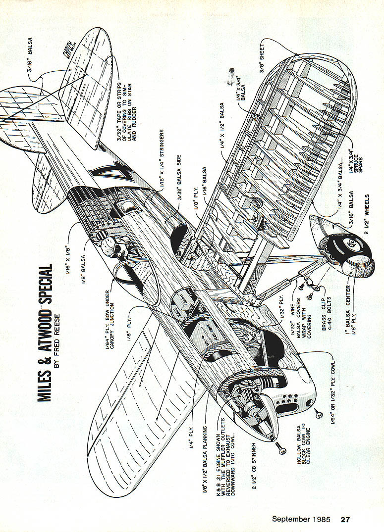
Miles-Atwood Special
BY FRED REESE
Overview
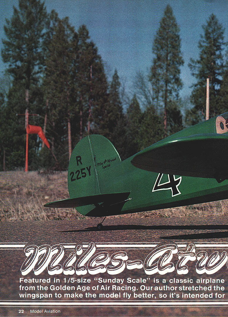
Featured in 1/5-size "Sunday Scale" is a classic airplane from the Golden Age of Air Racing. The model is intended for fun flying rather than competition; the author stretched the wingspan to improve flight characteristics. Designed for .20 to .25 cu. in. engines and a four-channel radio.
This is a classic racer from the Golden Age of Air Racing. Clean lines and streamlining made it competitive with other racers of its day that had twice the power. At one-fifth scale this still is a small model, and it is designed for .20–.25 cu. in. engines.
To many of us, building and flying model airplanes is a way of studying and preserving aviation history. There were many aircraft and people involved in pioneer aviation who are not well known, but they still contributed to modern aviation. The bravery of pilots who strapped themselves into machines that were just chalk lines on the floor three months earlier needs to be remembered. Air racing quickly changed military airplanes from biplanes to all-metal monoplanes that were double the speed; this technology became very important as we were thrown into World War II shortly thereafter.
We have all heard of the Gee Bee racers, Mr. Mulligan, and some of the other planes that won the Thompson and Bendix at the National Air Races. These unlimited air races were equal in stature to today’s Indianapolis 500 in auto racing. Also at the national event were at least a dozen other races for smaller displacement classes, including straight-line, city-to-city dashes, and pylon races. Some early racer-builders included Ben Howard, Art Chester, Steve Wittman, Clayton Folkerts, Keith Rider, Eldon Cessna, Gordon Israel, and Lawrence Brown.
History of the Full-Size Miles-Atwood Special
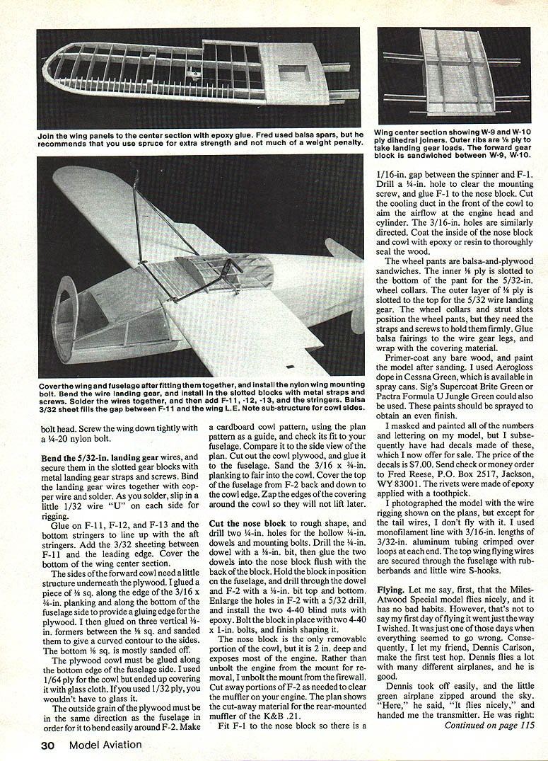
Lawrence Brown, famous for his B-2 Miss Los Angeles, built his first racer for pilot Lee Miles. The Miles-Atwood Special, named for its pilot and its sponsor, was built and first raced in 1933. The petite plane had a wingspan of only 16½ feet. The fuselage was conventional welded steel tubing covered with wood stringers and fabric. The wing used spruce spars and plywood ribs, was fabric-covered, and wire-braced for support. Power was a Menasco C45 four-cylinder engine of 363 cu. in. displacement, producing 185 hp.
In 1933 the Miles-Atwood Special raced as #6 without wheel pants or spinner, but took two firsts, two thirds, one fourth, and two fifths at the National Air Races. Planes qualifying for the 375 cu. in. class races could also fly in the under-550 and 1,000 cu. in. races and the Thompson. Top speed in 1933 was 170.14 mph around pylons and 210.64 mph in the dashes. Jimmy Wedell won the Thompson that year with his 985 cu. in. Wedell-Williams racer at 237.95 mph.
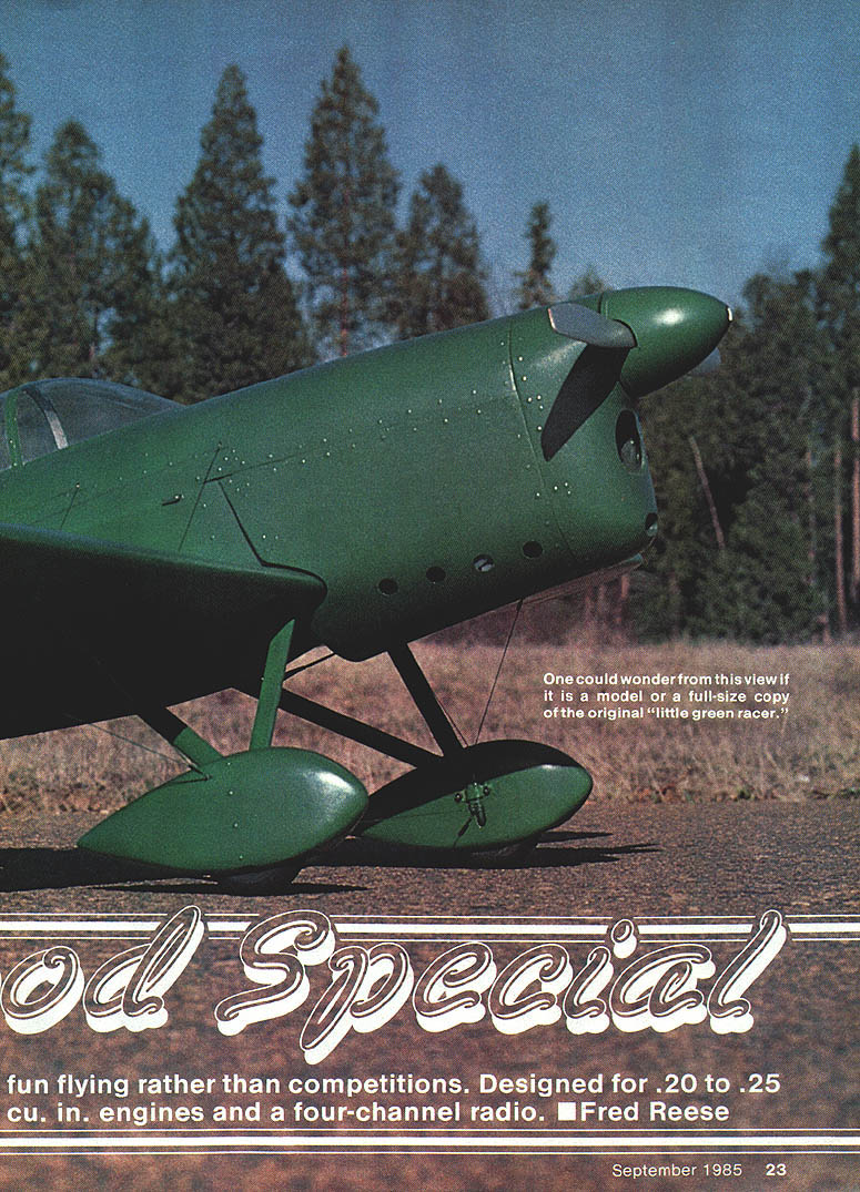
In 1934 the Miles-Atwood Special was given wheel pants, a spinner, and a close-fitting cowl, and it was painted all green with a new race number 4. At the Pan Am Races in New Orleans that year the little green racer won three firsts in the 375 cu. in. class. At the 1934 National Air Races in Cleveland it won six firsts, one third, and a fourth. Top speed rose to about 206 mph around the pylons and 233.44 mph in the Shell-sponsored dashes.
Lee Miles entered the Miles-Atwood Special in the Thompson Trophy Race but engine problems prevented it from finishing. Another Brown racer, Miss Los Angeles, finished second behind Roscoe Turner. The Miles-Atwood Special also won the Greve race in 1934 for engines less than 550 cu. in. Small, light, and highly streamlined, the airplane reached its peak in 1934–1935. Aircraft appearing then had cantilever wings and retractable landing gear, spelling the end of the wire-braced fixed-gear era.
Model Description
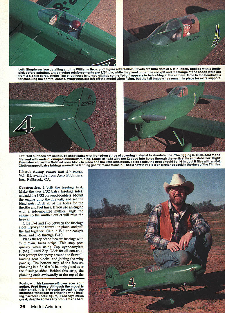
The model is very small at 1/5 scale yet has a relatively large fuselage. Scale wingspan is 39 inches; the author originally planned a scale-size wing, but after completing the basic fuselage structure he predicted a finished weight around four pounds. Consequently he kept the fuselage scale dimensions and stretched the wing to 45 inches to keep wing loading within reasonable limits. The wing still looks small and the overall appearance has suffered somewhat, but instead of being a beast the model is a pleasure to fly.
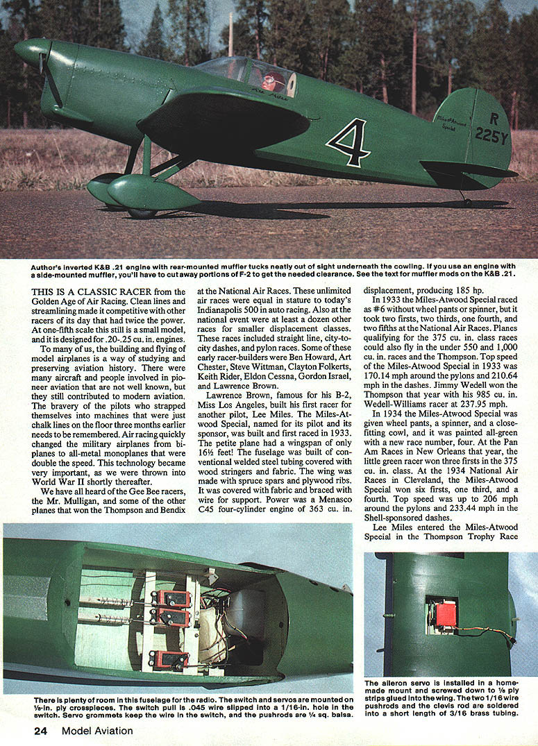
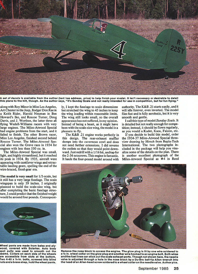
The K&B .21 engine works perfectly in this design. The rear-exhaust muffler dumps into the cavernous cowl and does not need further extensions; the author reversed the outlets so they point downward (redrill with a 1/16-in. drill bit and tap for 2‑56 setscrews). This engine hauls the four-pound model around with authority, starts easily, and will idle forever, even inverted. The model flies fast and is fully aerobatic, yet is very smooth and gentle.
The author calls this type of model "Sunday Scale." It is detailed but not enough for competition; instead, it should be flown regularly, as you would a Kadet, Kaos, Falcon, etc.
Sources and References
- If you decide to build this model, order the 1934–37 Miles-Atwood Special three-view drawing by Hirsch from Repla-Tech International. The two photographs included will help visualize details.
- Another excellent photograph of the Miles-Atwood Special as #4 appears in Reed Kinert's Racing Planes and Air Races, Vol. III (Aero Publishers, Inc., Fallbrook, CA).
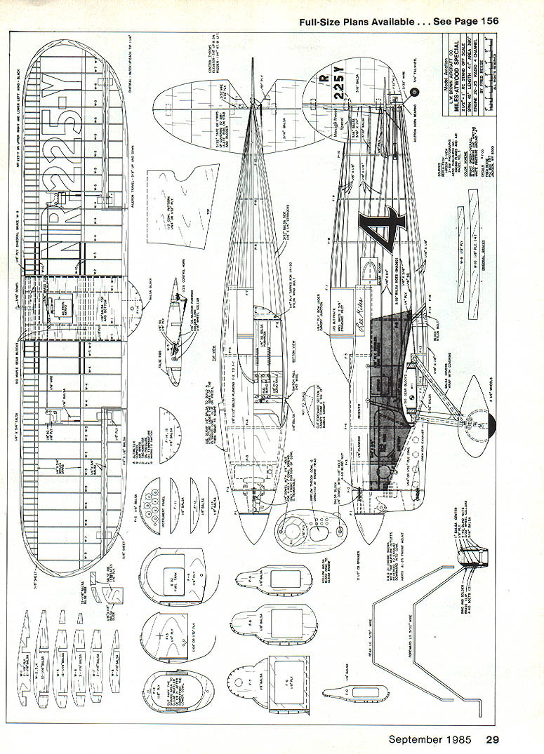
Plans / Illustrations
One scanned page contains the full-page plan/illustration (cutaway drawing) of the Miles-Atwood Special with many part callouts and dimensions. That scanned page contains no continuing article text — only the drawing title, author credit, and labeled parts. Other scanned pages contain full-size plans/illustrations only.
Construction
Fuselage
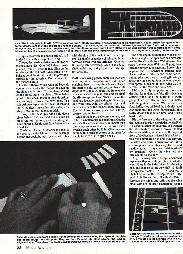
- Make the two 3/32-in. balsa fuselage sides and add the 1/32-in. plywood doublers.
- Mount the engine onto the firewall and set the blind nuts. Drill all holes for the throttle and fuel lines. If you use an engine with a side-mounted muffler, angle the engine so the muffler outlet will miss the firewall.
- Glue F-4 and F-6 between the fuselage sides. Epoxy the firewall in place and pull the tail together. Glue in F-2 (cockpit floor) and F-5 through F-10.
- Plank the top of the forward fuselage with 1/8 x 1/2-in. balsa strips. The bottom strip of the forward planking is 3/16 x 3/8-in. glued over the fuselage sides. Behind this strip the planking ends awkwardly at the top of the fuselage sides (no gluing surface), so bridge this with a strip of 3/32-in. square balsa.
- The rudder needs a platform on the top of the fuselage sides. Glue 3/32-in. sheet, cross‑grained, from F-10 to the tail. Glue on the rudder and tail post. Glue some 1/8 x 1/4-in. balsa around the stabilizer slot to provide a surface for the covering; do the same for pushrod exits.
- On the full-size aircraft, cooling air exited at the rear of the cowl on the sides and bottom. To simulate side exits, glue a piece of 1/8-in. balsa to the sides ahead of the side stringers, ending just inside the cowl edge. Taper the side stringers into this 1/8-in. sheet and taper 1/16-in. sheet into the sides, creating a slot when finished.
- Epoxy in the 1/4-in. plywood wing hold-down block behind F-6, and add F-15. Glue on all top, bottom, and side stringers. Glue on the 1/32-in. plywood tank floor between F-2 and F-3.
- The block that forms the back of the scoop (left side of fuselage behind cockpit) must be shaped to fair with the cockpit and stringers. Think of it as a thin aluminum piece screwed down over stringers. Glue on the scoop after covering.
- Glue in the 3/32-in. sheet stabilizer and prepare the fuselage for covering.
Wing (Panels and Center Section)
- Build each wing panel complete with ailerons as one-piece units until after shaping; then cut away the ailerons.
- Taper the spars evenly, top and bottom, from full depth at W-7 to 7/16 in. at the tip. Shim up the spars 1/8 in. over the plan and glue on all ribs except W-2 and W-3.
- Glue on the leading edge, aileron framing, trailing edge, and wing tips. Add aileron ribs; carve and shape leading edge and tips (use a razor plane and a large coarse sanding block).
- Glue in 1/8-in. plywood bellcrank mounts, and install bellcranks and pushrods. Cut servo–bellcrank pushrods 1/4 in. longer than the wing center so the two wires will overlap by 1/2 in.
- Glue in some scrap 1/4-in. blocks on top of the spars for the 1/32-in. wire "U" rigging hooks.
Wing center section:
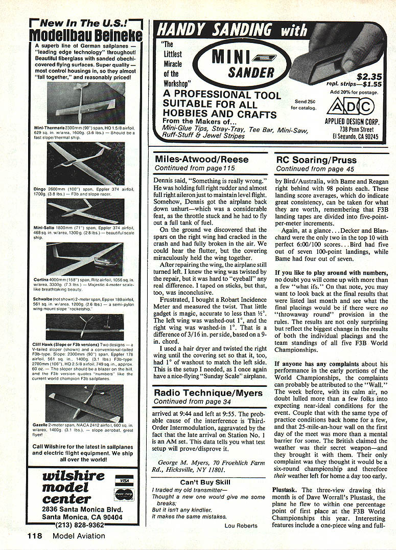
- Glue the spar sections between the two W-10s. Glue the four W-1 ribs over the spars (the two outer W-1s are 1/8-in. ply), then fill in the bottom 1/16-in. sheeting.
- Epoxy-glue in the W-9, W-8, W-7 wing blocks and V-9. Glue on the leading edge and the top sheeting (leave a cutout for the servo). Join wing panels with epoxy, blocking up each wing tip 1/4 in. Glue in the W-2 and W-3 ribs.
- Make 1/16-in. ply templates as shown on the plan for making false ribs: one template is a cutting guide and the other a width gauge. Glue up a strip of 1/4-in. x 16-in. balsa with the grain crosswise. With a sharp X‑Acto knife slice off 56 little ribs and glue them into the wing. This is quicker and easier than it sounds.
Fit the fuselage to the wing and install the leading-edge dowel to fit the hole in F-4. Align the wing in the fuselage and hold with pins while you glue F-14 to the wing. Glue in the balsa block for the wing bolt and shape it to line up with F-15. Drill through the block, F-14, F-15, and the 1/8-in. ply hold-down in the fuselage with a 3/16-in. drill bit; follow with a 1/4-20 tap. Remove the wing and drill out the wing block with a 1/4-in. drill; countersink for the bolt head. Screw the wing down tightly with a 1/4-20 nylon bolt.
Landing Gear and Wheel Pants
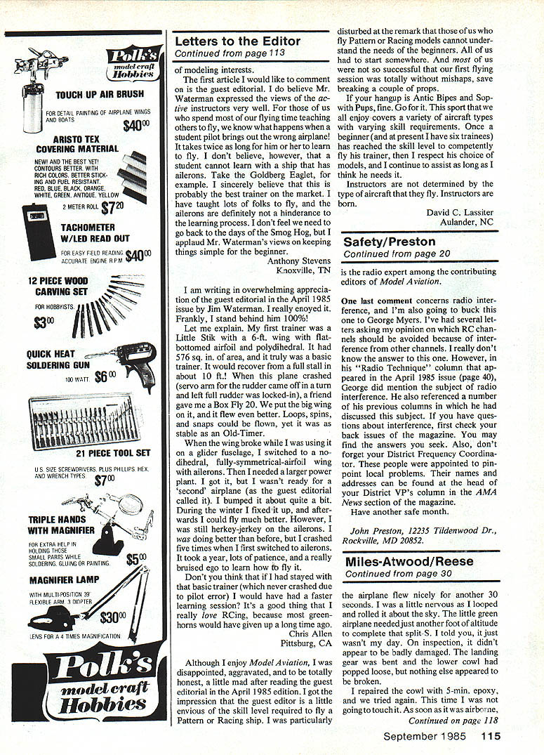
- Bend the 5/32-in. landing gear wires and secure them in the slotted gear blocks with metal landing gear straps and screws. Bind the landing gear wires together with copper wire and solder. As you solder, slip in a little 1/32-in. wire "U" on each side for rigging.
- Glue on F-11, F-12, and F-13 and the bottom stringers to line up with the aft stringers. Add 3/32-in. sheeting between F-11 and the leading edge. Cover the bottom of the wing center section.
- The wheel pants are balsa-and-plywood sandwiches. The inner 1/8-in. ply is slotted on the bottom for the 5/32-in. wheel collars. The outer 1/8-in. ply is slotted on the top for the 5/32-in. wire landing gear. The wheel collars and strut slots position the wheel pants, but they need straps and screws to hold them firmly. Glue balsa fairings to the wire gear legs and wrap with the covering material.
Cowl and Nose Block
- The sides of the forward cowl need a little structure under the plywood. Glue a piece of 1/8-in. square along the edge of the 3/16 x 3/4-in. planking and along the bottom of the fuselage side to provide a gluing edge for the plywood. Glue three vertical 1/8-in. formers between the 1/8-in. square and sand them to give a curved contour to the sides. The bottom 3/8-in. square is mostly sanded off.
- The plywood cowl must be glued along the bottom edge of the fuselage side. The author used 1/64-in. ply for the cowl and ended up covering it with glass cloth; if you use 1/32-in. ply you would not need to glass it.
- Ensure the outside grain of the plywood runs the same direction as the fuselage for easy bending around F-2. Make a cardboard cowl pattern using the plan as a guide and check fit to your fuselage. Cut out the cowl plywood and glue to the fuselage. Sand the 3/16 x 3/4-in. planking to fair into the cowl. Cover the top of the fuselage from F-2 back and down to the cowl edge. Zap the edges of the covering around the cowl so they will not lift later.
- Leave a 1/16-in. gap between the spinner and F-1. Drill a 1/4-in. hole to clear the mounting screw and glue F-1 to the nose block. Cut the cooling duct in the front of the cowl to aim airflow at the engine head and cylinder; the 3/16-in. holes are similarly directed. Coat the inside of the nose block and cowl with epoxy or resin to seal the wood.
Covering, Finishing, and Paint
- The author used Solatex for covering to retain fabric texture. Fill the weave with a primer coat at the top and front of the fuselage where it was aluminum on the full-size aircraft. Solatex and similar iron-on fabric coverings are easy to use and accept sprayed-on finishes (do not try brushing). Cover the wing and the fuselage up to the cowl.
- Primer-coat any bare wood and paint after sanding. The author used Aerogloss dope in Cessna Green (available in spray cans). Sig's Supercoat Brite Green or Pactra Formula U Jungle Green are alternatives. Spray paints for an even finish.
- Rivets were simulated with epoxy applied with a toothpick.
Rigging and Bellcrank/Servo Details
- Glue in the 1/8-in. ply bellcrank mounts, install bellcranks and pushrods, and prepare the servo mounting in the center section as noted earlier.
- The author photographed the model with wire rigging as shown on the plans, but except for the tail wires he does not fly with it. He used non‑ferromagnetic line with 3/16-in. lengths of 3/32-in. aluminum tubing crimped over loops at each end. Top wing flying wires are secured through the fuselage with rubber bands and small wire S-hooks.
Flying
The Miles-Atwood Special model flies nicely and has no bad habits, but the author’s first day did not go smoothly. Dennis Carlson made the first test hop and reported that it "flies nicely." On the author's first flight, after about 30 seconds of aerobatics, the airplane needed another foot of altitude to complete a split-S and was damaged in the ensuing landing. The landing gear was bent and the lower cowl had popped loose; otherwise little appeared broken.
After repairing the cowl with 5-minute epoxy, a subsequent flight resulted in the airplane flying with severe control input required: Dennis had to hold full right rudder and almost full right aileron to maintain level flight. He returned the airplane despite a stuck throttle and having to fly out a full tank.
On the ground it was discovered that the spars on the right wing had cracked in the earlier crash and had fully broken in the air. The covering had miraculously held the wing together. After repairing the wing, the airplane still turned left. The author suspected wing twist but found it hard to eyeball.
Frustrated, he bought a Robart Incidence Meter and measured wing twist. The meter is accurate to less than 1/2°. Measurements showed the left wing was washed out 1° and the right wing was washed in 1° — a difference of 3/16 in. per side based on a 9-in. chord. Using a hair dryer, he twisted the right wing until the covering set so it had 1° washout to match the left side. With this setup, the model again became a nice-flying "Sunday Scale" airplane.
Decals and Extras
- The author masked and painted all numbers and lettering on his model. He subsequently had decals made and offers them for sale.
- Price: $7.00 for the decal set.
- Send check or money order to: Fred Reese, P.O. Box 2517, Jackson, WY 83001.
Notes
- Use Zap cyanoacrylate (CyA) for most construction (author used Zap CA+), except epoxy around the firewall, landing gear blocks, and joining wing panels.
- Seal and epoxy areas subject to fuel and heat exposure.
- Adjust wing incidence and washout precisely; small angular differences produce noticeable flight tendencies.
Transcribed from original scans by AI. Minor OCR errors may remain.

