

Miniature: Disc Sander
Bob Kopski
Overview
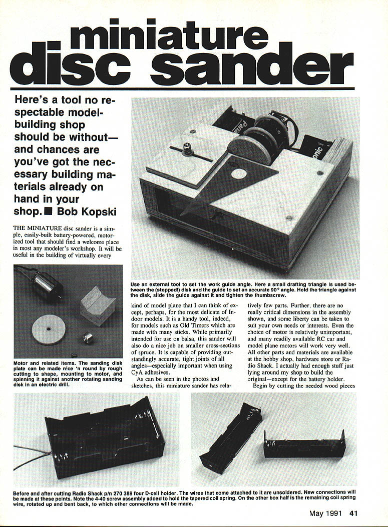
Here's a tool no respectable model-building shop should be without—and chances are you've got the necessary materials already on hand. The miniature disc sander is a simple, battery-powered motorized tool useful for most model planes (except the most delicate indoor models). Primarily intended for balsa, it also works well on small spruce sections and provides outstandingly accurate, tight joints of all angles—especially important when using CyA adhesives.
Materials and stock
- Base plate: 3/16–1/4 in. flat wood (original used 1/4-in. ply)
- Side rails: 1-in. x 2-in. pine molding (actual ~3/4 in. x 1-1/2 in.)
- Work table surface, adjustable sanding guide, and 2-in. disk plate: 1/4-in. modeling plywood
- Front switch panel: thin wood (I used 1/8-in. Lite Ply)
- Four 1/4-in. sq. wood strips (box in battery holders)
- Assorted small wood pieces for motor mount
- Radio Shack 4-D battery holder (modified)
- Motor: any small RC/model motor (540-size or .05 plane motors work well)
- Sullivan Golden Rod inner plastic for motor clamps (RC push-rod plastic)
- Electric model propeller adapter (for mounting the sanding disk)
- Screws, nuts, blind nuts (6-32 and 4-40), 2-56 machine screws, washers
- Sandpaper: 120–150 grit (silicon carbide or aluminum oxide preferred)
- Double-stick carpet tape or rubber cement/rub-on adhesive for sandpaper
- Self-stick rubber feet, soft foam for under table top
- Optional: DPDT center-off switch for reversible rotation
Cutting the wood parts
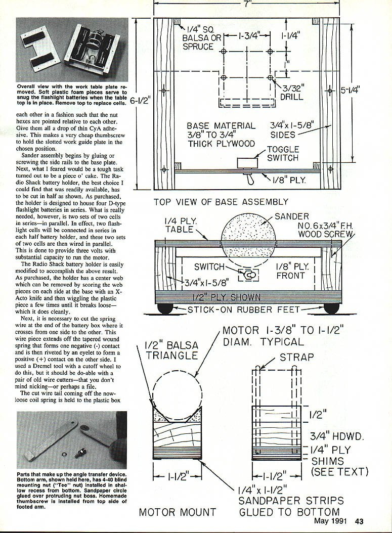
- Cut the base plate, side rails, work table, adjustable sanding guide and the 2-in. diameter sanding disk from the stocks noted above.
- The front panel (switch mounting) can be any thin wood; glue it to the front of the side rails later.
- The work guide: original was 2-1/2 in. square, 1/4-in. ply with a notch. If that's difficult, glue two 1-1/4-in. plates separated by 3/32 in., held by 1/4-in. x 1/4-in. spruce end pieces.
Guide plate details
- Glue two strips of 120 or 150 grit paper to the bottom of the guide plate to provide friction so the guide won't slip on the table under thumbscrew pressure.
- Drill three locations in the table surface to accept 6-32 blind mounting nuts for maximum flexibility in angular placement of the guide. The off-center plate slot plus these blind-nut positions allows total flexibility in guide angle.
- I habitually use the guide on the left side of the table, but you may install blind nuts on either or both sides.
Thumbscrew for the guide plate
- Make the thumbscrew from a 1-in. 6-32 machine screw.
- Build the thumb head by using three 6-32 nuts separated by spring lock washers and jammed together so the nut hexes are pointed relative to each other. Give them a drop of thin CyA adhesive to lock the assembly. Choose screw length so it won't hit batteries underneath.
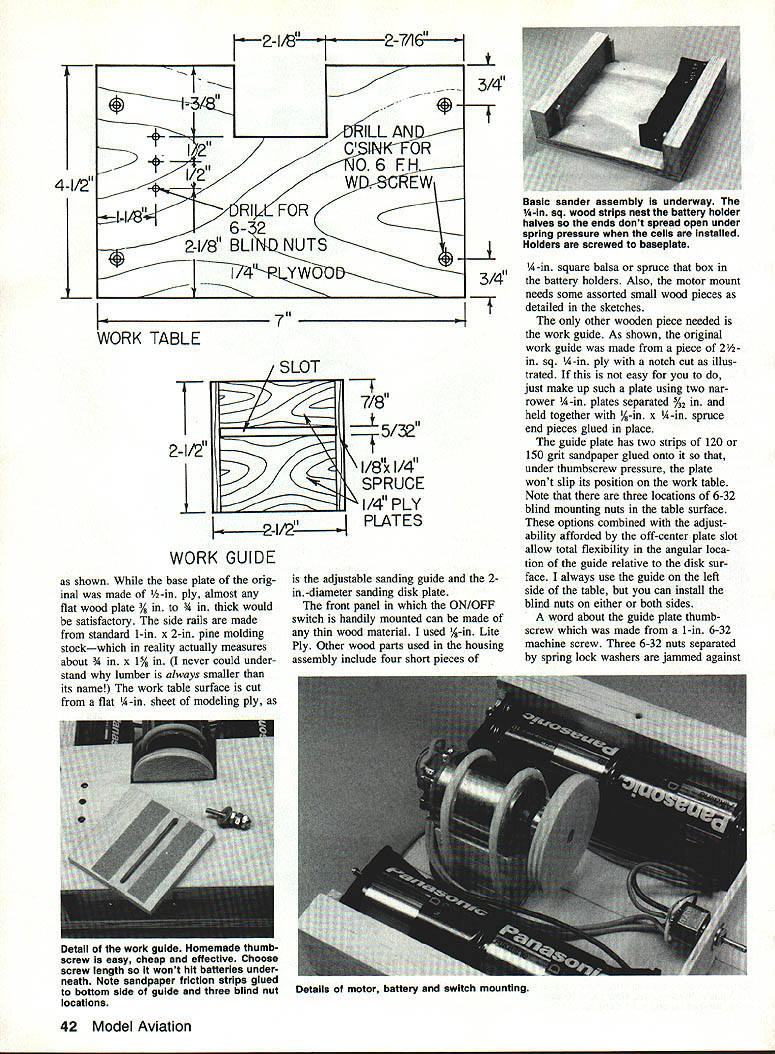
Battery holder modification (Radio Shack 4-D holder)
- The holder originally houses four D cells in series. For this sander, you need two sets of two cells in series wired in parallel to provide ~3 volts with higher capacity.
- Remove the center web by scoring at its base with an X-Acto knife and snapping it out.
- Cut the spring wire that crosses from one side to the other (this tail forms a positive contact on the opposite side). Use a Dremel cutoff or stout cutters. Re-affix the cut spring tail to the plastic box with a 1/2-in. 4-40 screw, washer, solder lug and nut—this provides an electrical connection point.
- Solder another connection to the short piece of wire remaining under the positive contact rivet.
- Cut the battery holder in half down the middle of the box bottom (score repeatedly with an X-Acto until through). You’ll end up with two 2-cell holders.
Mounting the battery halves
- Set each half-holder against the wood side pieces, locate mounting holes on the base plate, and mount each with two No. 6 x 3/8-in. wood or sheet metal screws.
- CyA the four 1/4-in. sq. x 1/4-in. wood strips to the side rails at each end of the battery boxes so the ends don't spread when cells are inserted.
- Glue the front switch panel in place against the front wood strips.
Motor selection and mount height
- Many inexpensive 540-size model car motors or .05 plane motors run well on the three-volt packs described. Running motors on higher voltages gives no real advantage and reduces battery life while increasing noise and vibration.
- Neutral-timed motors (or adjustable-to-neutral) are preferred because they run equally well in either direction; timed motors may favor one direction (usually CCW).
- The final motor mount height must be set with shims glued to the bottom of the motor mount so the motor shaft center (and sanding surface) is level with the table surface—this yields exactly half the disk above the tabletop.
Motor V-block and clamps
- Use two clamps made from the yellow inner parts of Sullivan Golden Rods (available in two diameters). Cut two pieces so that when wrapped over the motor/mount the ends fall about 1/8 in. above the base plate.
- Draw the plastic C-clamps tight with four 2-56 machine screws inserted from the bottom of the base plate. The screws form threads in the plastic (or tap the plastic with a 2-56 tap first).
- Glue a piece of 120 or 150 grit sandpaper to the bottom of the motor V-block assembly (including any shims). When the clamps are tightened, this sandpaper presses against the base plate and prevents motor/mount slip.
Sanding disk and prop adapter
- Use a 2-in. diameter disk cut from flat 1/4-in. plywood (larger is not recommended).
- Mount the disk to the motor shaft with an electric model propeller adapter (manufacturers: Astro, Hobby Lobby, Goldberg, Great Planes, etc.). You may need to shorten the adapter shank or add shims because the disk is thinner than a propeller hub.
- Drill the disk in the center to fit the adapter shank snugly. Countersink from the front to accept a flathead mounting screw. I cut a 1/4-in.-long screw from a longer 6-32 machine screw; the length you need may vary.
- Tighten the prop adapter set screw onto the motor shaft flat. Check that the disk runs true (no wobble). If the disk wobbles:
- Check the disk for warp and that it sits flat against the adapter.
- Ensure the disk screw and adapter set screw are snug.
- If wobble persists, mark the high spot by holding a pencil on the table near the disk and rotating the disk by hand. Loosen the disk screw and try a small off-center paper or tape shim between disk and adapter to correct the runout. Patience yields a true-running disk.
Attaching sandpaper to the disk
- Use 120 or 150 grit; silicon carbide or aluminum oxide are best for wear (garnet is acceptable).
- I use double-stick carpet tape for easy replacement. Rub-on glue stick or rubber cement also works. Be sure the attachment method allows easy paper removal and replacement. I have not tried self-adhesive sandpaper for this application.
Mechanical assembly and alignment
- Glue or screw the side rails to the base plate.
- Temporarily mount the motor/mount with plastic clamps snugged lightly so it can still be moved.
- Temporarily hold the work table in place with four No. 6 x 1/4-in. flat-head wood screws.
- Adjust the motor/mount so the disk face is about 1/32 in. from and parallel to the table cutout, and the disk center is level with the table top. Tighten clamp screws.
- Confirm the disk face is perpendicular (vertical) to the table surface. If slightly off, snug either the front or rear clamp or insert a thin paper shim between motor and mount front or rear. Remove the table top for final checks.
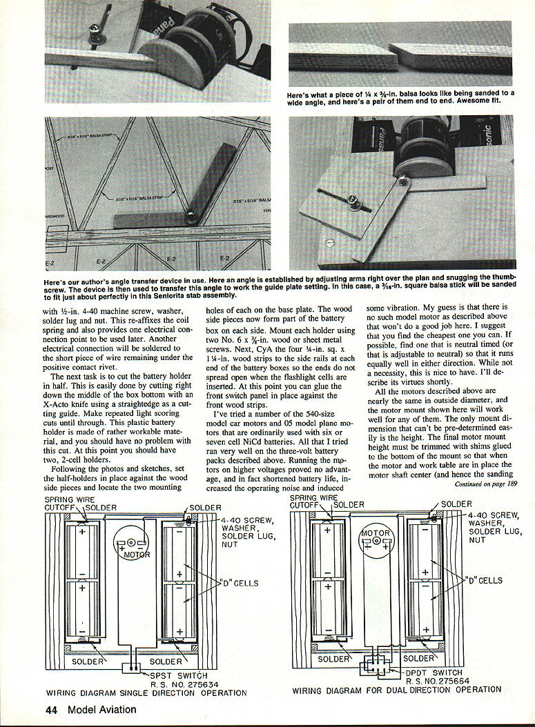
Wiring and switch options
- Simple single-direction wiring: motor runs one chosen direction. Select direction by reversing wires at the motor. Work is always held on the side of the disk where rotation presses the work against the table. With timed motors that favor CCW, you must work on the left side of the disk.
- Reversible wiring: use a DPDT center-off switch to reverse rotation by flipping the switch to either side of center (OFF). This allows approaching the disk from both sides—useful if you frequently switch which side you work from. Neutral-timed motors work equally well either way.
Final setup and testing
- Mount four self-stick rubber feet on the bottom of the base plate.
- Install the four cells and check motor/switch operation.
- Glue pieces of 1/2-in. thick soft plastic foam to the underside of the table top so it presses on the flashlight cells (helps hold them in place).
- Install the work table top and the guide. Use a small drafting triangle to align the guide to the disk for a 90° starting position: hold the triangle against the disk, slide the guide against it, and tighten the thumbscrew.
Operating tips
- Feed material slowly against the disk; don't force it. This is not a high-power machine but has adequate power if you let the sandpaper do the work.
- Avoid heavy loading that noticeably slows the disk.
- Turn the switch off between sticks to conserve battery.
- Use alkaline cells for best performance and life; motors draw about 1–2 amps at idle and more under load.
- With normal use, battery life has been very satisfactory (I used cells across many parts and demonstrations and they’re still going strong).
Optional accessory: Angle transfer device
- Materials:
- Two pieces of 5/16-in. birch ply, 1/2-in. wide: one 3 in. long, the other 3-1/2 in. long
- A short foot piece ~7/16 in. long glued under the longer arm at the end opposite the pivot
- 4-40 machine screw and thumb nut for the pivot
- A 4-40 blind nut recessed ~3/16 in. in the bottom surface of the shorter arm (flatten or remove the nut teeth so it sits flush)
- A small friction disk of sandpaper glued over the nut boss
- Assembly:
- Fasten the two arms with a 4-40 machine screw and a thumbscrew arrangement as used for the sanding guide.
- The recessed blind nut’s protruding boss (~1/8 in.) forms the pivot for the top ply piece; the friction sandpaper disk holds the chosen angular setting when the thumbscrew is tightened.
- Ensure the screw length does not protrude below the lower arm.
- Use: This accessory transfers angles precisely from one part to another and yields very high-precision angular fits.
Final remarks
This sander is one of the most useful tools I've used in 40+ years of model building. With proper setup and gentle operation, it produces extremely accurate joints—perhaps the best you've achieved. Enjoy the tool and the increased precision it brings to your building.
Transcribed from original scans by AI. Minor OCR errors may remain.

