


Miniature Spin Tunnel
By David Robelen
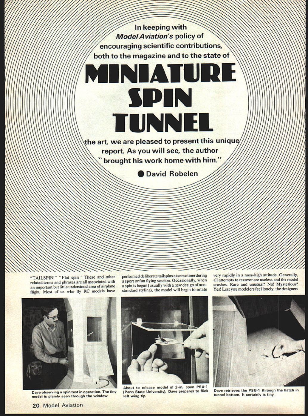
"Tailspin!" "Flat spin!" — these and other related terms describe an important but little understood area of airplane flight. Most RC modelers have performed deliberate tailspins during sport or fun flying sessions. Occasionally, when a spin begins (often with a new design or non‑standard styling), the model will rotate very rapidly in a nose‑high attitude and recovery attempts fail. This phenomenon is not limited to models; full‑scale aircraft designers have faced similar dilemmas.
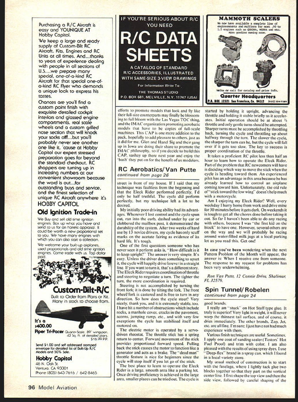
The study of aircraft tailspins has attracted significant research effort. One valuable facility for this research is the spin tunnel: a wind tunnel standing vertically with air drawn upward by a fan mounted at the top. Models are launched with a whirling motion into the rising air while the fan rpm is adjusted to balance the model’s descent rate, allowing close study of motion and behavior. Such facilities are rare; two are noted in the free world — NASA Langley (Virginia) and one in France. The NASA chamber is about twenty feet across and typically tests models around two feet in wingspan, often equipped with RC for control and recovery studies.
At NASA‑Langley I was exposed to spin‑tunnel tests and became fascinated with this safe method for testing critical motions. Lacking access to a federal facility, I decided to build a miniature spin tunnel at home. The design is not a scale model of the larger units but is tailored to the intended job. Detailed construction drawings are omitted here; the following is a general description of materials, methods, and observations.
Spin Tunnel Construction
Fan, structure, and finish
- A 20‑inch floor fan (variable transformer controlled) provides the airflow.
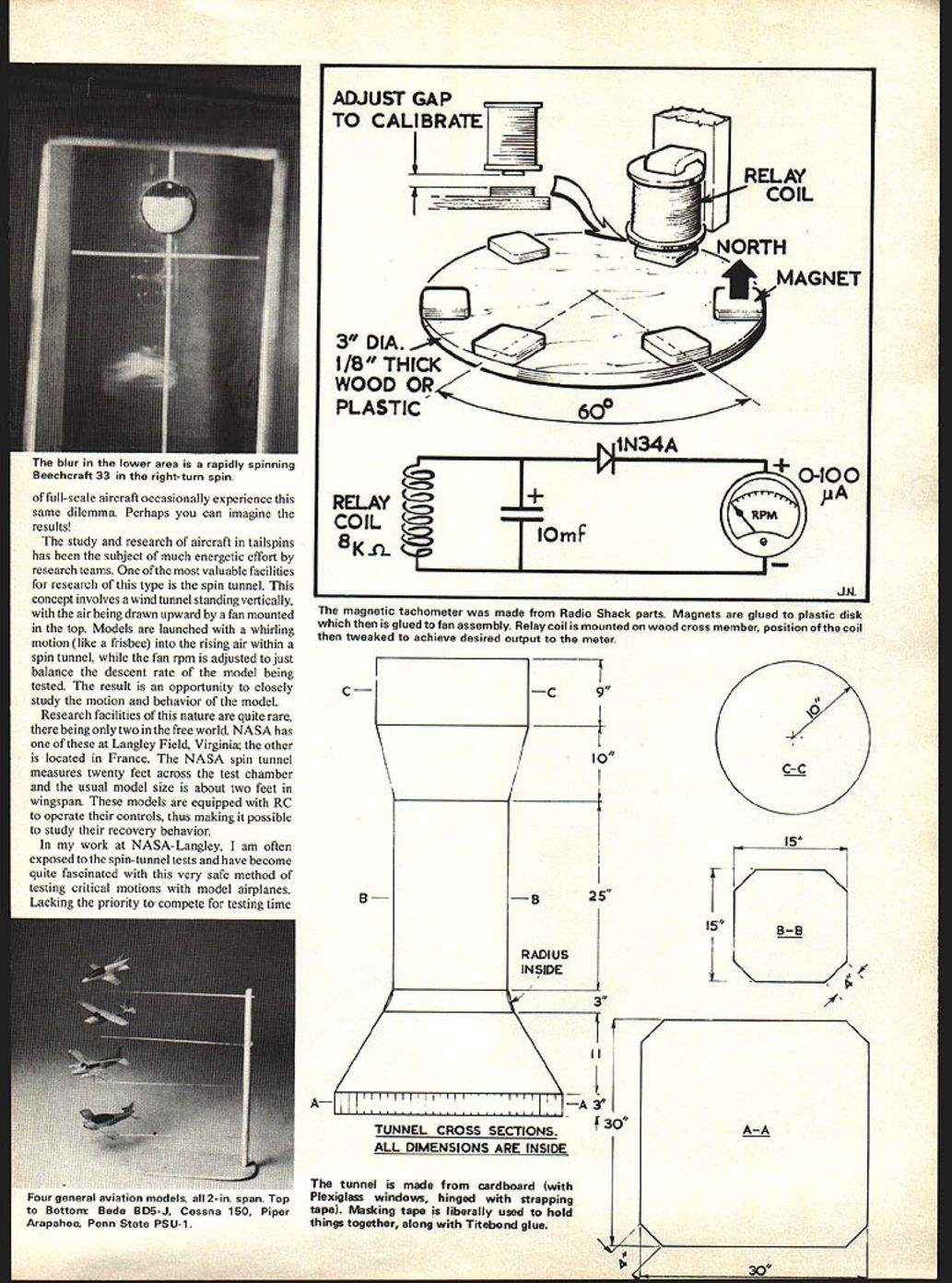
- The tunnel structure is cardboard with Plexiglass windows hinged with strapping tape. Masking tape and Titebond glue hold things together.
- Strips of wood support the fan at the top and provide a bottom frame and legs.
- A flow‑straightener grid (cardboard is acceptable) occupies the bottom; a silk‑like polyester fabric net stretched across the grid smooths the airflow and catches models.
- A large hatch is cut in the bottom cone for retrieving models.
- Interior lighting is provided by a desk lamp. The interior is painted flat black for visibility; the exterior is spray‑painted silver.
Tachometer
- Constructed from Radio Shack parts: small magnets glued to a plastic disk attached to the fan assembly.
- A relay coil mounted on a wooden cross member senses the magnets; the coil position is adjusted to get the desired meter output.
Measuring and Weighing Tiny Models
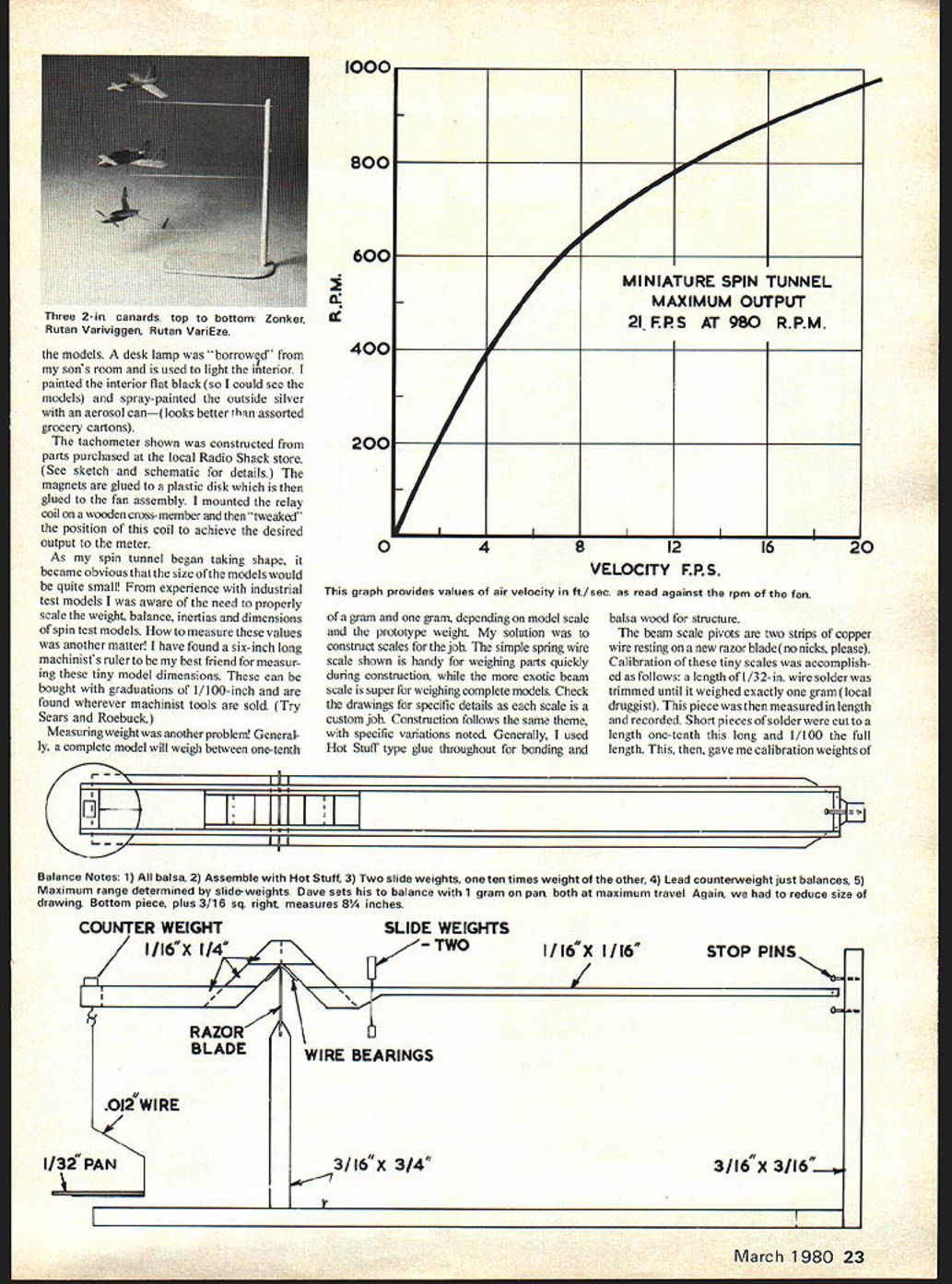
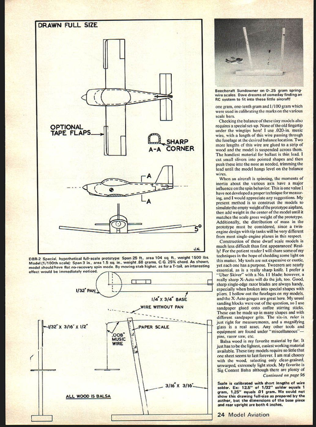
Scaling weight, balance, inertias, and dimensions is important for meaningful spin tests. Small model dimensions are measured using a six‑inch machinist’s ruler with 1/100‑inch graduations (available where machinist tools are sold).
Measuring weight:
- Complete models typically weigh between 0.1 gram and 1.0 gram depending on scale and prototype.
- Two custom scales were used:
- A simple spring‑wire scale for quick part weights.
- A beam scale for complete models. The beam pivots rest on two strips of copper wire seated on a new razor blade (no nicks).
- Calibration: a length of 1/32‑inch solder wire was trimmed until it weighed exactly one gram (obtained from a local druggist). This piece was measured; shorter pieces (one‑tenth and one‑hundredth the length) provided 0.1 g and 0.01 g calibration weights.
Checking balance:
- Do not use fingertip balancing. Instead, pass a length of .020‑inch music wire through the fuselage at the desired balance point.
- Support the model on two other lengths of .020‑inch wire glued to a strip of wood so the model suspends across them.
- Ballast with thin lead slivers cut to pointed shapes and pushed into the nose; trim until the model hangs level.
Moments of inertia have a major influence on spin behavior. I have not developed a precise method to measure these and welcome suggestions. My current practice: build models to simulate the prototype’s empty weight, then add weight in the center to match prototype gross weight, while considering mass distribution (e.g., twin‑engine with tip tanks vs. single‑engine).
Tools, Materials, and Finishes
Tools
- Tweezers, a very sharp knife (I prefer an "Uber Skiver" with a No. 11 blade or a sharp X‑Acto), single‑edge razor blades (shaped with pliers), gouge blades for hollowing, sandpaper glued to coffee stirring sticks (various shapes and grits), a six‑inch ruler, and a magnifying glass.
- Miscellaneous: pins, razor saw, etc.
Materials
- Balsa wood (select clear‑grained, unwarped, very light stock). My favorite is Sig Contest Balsa, though there are many good brands.
- Hot Stuff type glue (lightweight and sets quickly) is preferred; Zap, Jet, and similar adhesives also work.
Finishes
- Sometimes a coat of sanding sealer (Testors' Hot Fuel Proof) followed by color trim.
- Spray dyes (e.g., Deep‑Flex in a spray can) give good results.
Model Construction Techniques
- Fuselage
- Lightly tack glue two balsa blocks together along the vertical center line.
- Shape the top view, then the side view, then refine contours.
- Separate the blocks and hollow the interior with gouge blades; nose may be left solid; tail aft of the wing should be very light.
- Wing
- Cut planform from suitable balsa sheet, form the airfoil, and set dihedral.
- Mount by cutting the appropriate fuselage area, gluing the wing, and fairing as needed.
- Tail Surfaces
- Keep extremely light; sand sheet balsa thin (about .010 inch) and cut tail pieces from this.
- Fasten with tiny drops of Hot Stuff glue.
- Controls and trimming
- In most cases I set control surfaces by moistening and bending—no hinges.
- A good starting setup: elevator up, rudder in the spin direction, ailerons against the spin (e.g., up elevator, left rudder, right aileron for a given spin).
Launching and Test Procedure
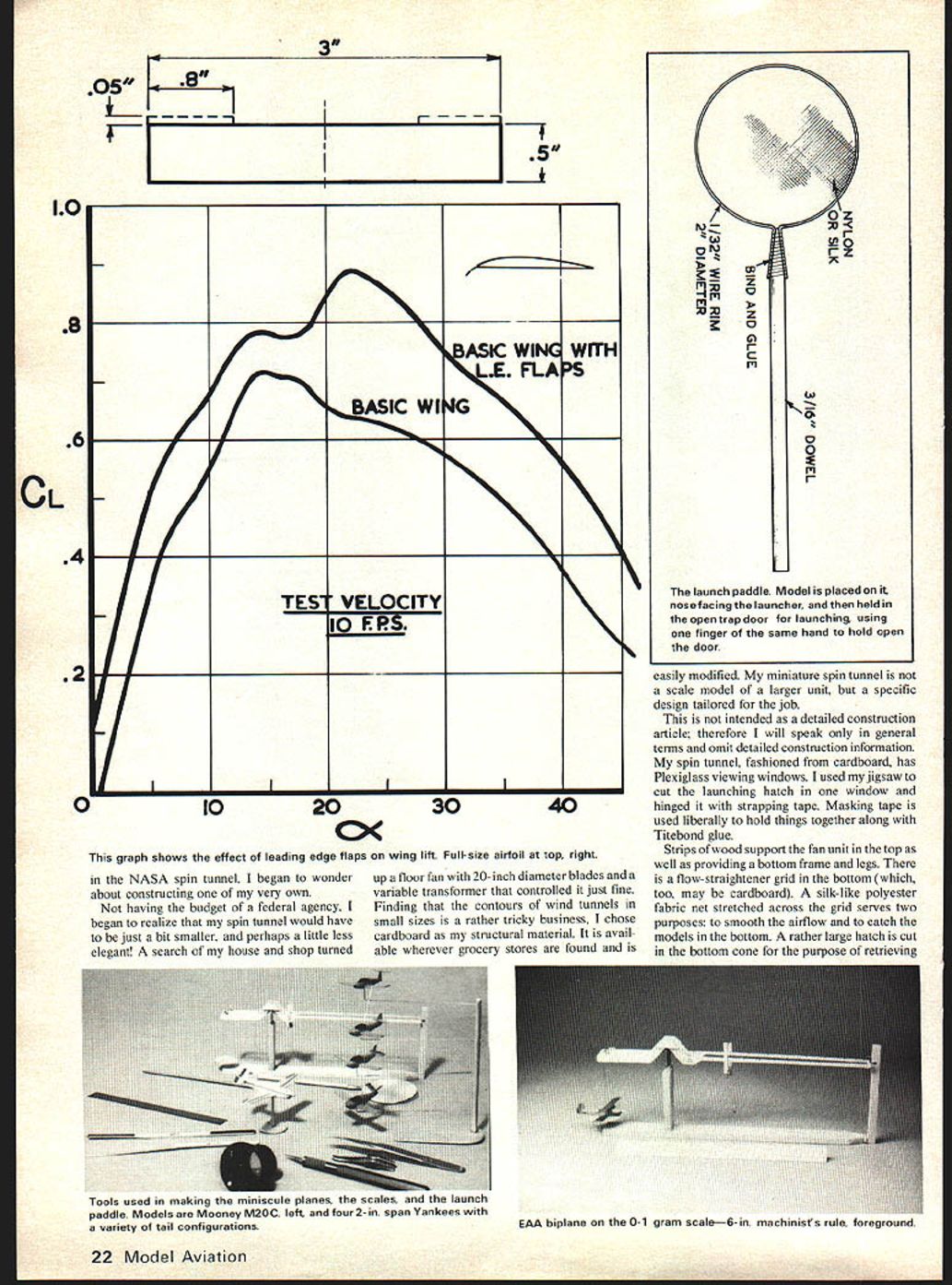
- A small paddle is used for launching: dowel handle, wire rim, and fine mesh fabric center.
- Place the model on the paddle nose facing the launcher and hold it in the open trap‑door with one finger.
- Launch by gently flicking a wing tip with a finger of the other hand to start spin and propel the model into the tunnel throat.
- Allow the trap‑door to fall shut and adjust tunnel rpm to balance the spinning model.
- Practice is important; launching happens quickly and takes some getting used to.
Observations and Aerodynamic Notes
During testing I encountered a recurring phenomenon: some models would not maintain a spin under conditions where I expected them to. Suspecting scaling effects such as Reynolds number differences, I experimented by applying a strip of Scotch tape to the wing leading edge of a problem model to form a crude flap. Results were dramatic:
- The model spun readily.
- Spin rate, spin angle of attack, and other behaviors closely matched expectations.
- A flap of about one‑half wing span and one‑tenth chord proved effective.
- With such tape flaps, most models spun as expected despite uncertainties about prototype behavior.
To investigate, I built a small wing and measured forces in another small wind tunnel with and without tape flaps. The lift curves showed increased lift, especially at higher angles of attack encountered in a tailspin. I present the data without drawing lofty conclusions.
Most of my models are patterned after current general‑aviation lightplanes. This is both helpful and limiting: helpful because the shapes are familiar; limiting because there is little published data on full‑scale spin behavior for direct comparison.
Limitations and Final Remarks
- The miniature spin tunnel and dwarf‑scale models are useful for demonstrations and exploratory testing, but scaling issues (Reynolds number, moments of inertia, mass distribution) can affect direct comparison with full‑scale aircraft.
- Careful measurement of weight, balance, and thoughtful mass distribution help, but measuring moments of inertia at these scales remains a challenge.
- The tape‑flap observation suggests leading‑edge modifications can alter high‑angle behavior; further systematic study would be valuable.
Construction and experimentation with a home‑built spin tunnel can be rewarding and educational. Practice, patience, and careful attention to small‑scale measurement and trimming techniques yield useful and often surprising results.
Transcribed from original scans by AI. Minor OCR errors may remain.

