
MISFLIT
By L. F. Randolph
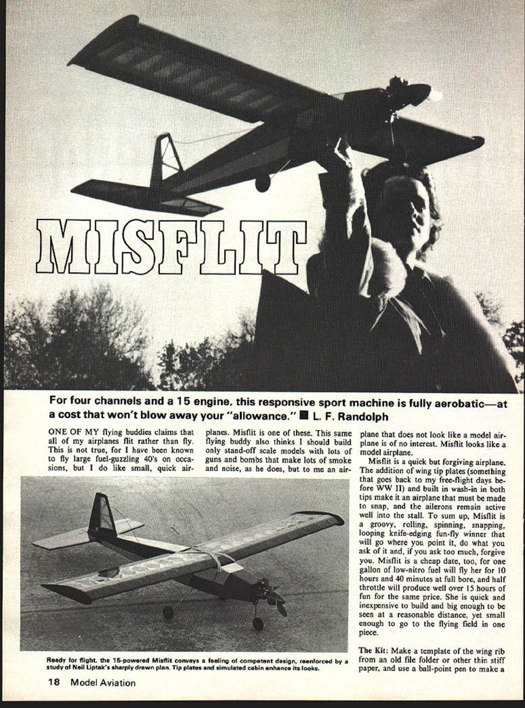
One of my flying buddies claims that all of my airplanes flit rather than fly. This is not true, for I have been known to fly large fuel‑guzzling .40s on occasions, but I do like small, quick airplanes. Misflit is one of these. This same flying buddy also thinks I should build only stand‑off scale models with lots of guns and bombs that make lots of smoke and noise, as he does, but to me an airplane that does not look like a model airplane is of no interest. Misflit looks like a model airplane.
Misflit is a quick but forgiving airplane. The addition of wing tip plates (something that goes back to my free‑flight days before WWII) and built‑in wash‑in in both tips make it an airplane that must be made to snap, and the ailerons remain active well into the stall. To sum up, Misflit is a groovy, rolling, spinning, snapping, looping, knife‑edging, fun‑fly winner that will go where you point it, do what you ask of it and, if you ask too much, forgive you. Misflit is a cheap date, too: one gallon of low‑nitro fuel will fly her for about 1½ hours at full bore; half throttle will give significantly longer duration. She is quick and inexpensive to build and big enough to be seen at a reasonable distance, yet small enough to go to the flying field in one piece.
The Kit
Make a template of the wing rib from an old file folder or other thin stiff paper, and use a ball‑point pen to make a printed layout on two pieces of medium‑hard 1/16" x 3" x 36" balsa. Move the template around to find the most ribs that can be cut from each sheet. You need 24. After the ribs have been cut out and gang‑sanded to the same shape and size as the template, take four of them from the center of the stack and cut 1/16" off the top and bottom of each; these are the center ribs that will receive sheeting—mark them R2.
The trailing edge sheeting is cut from 1/16" x 3" x 36" hard balsa. Because there are four strips and they are an inch wide, the fourth one must be made by splicing. When three have been stripped, cut them to a length of 22‑1/16". The remaining one‑inch strips are spliced to form the fourth. The wing spars are stripped from a sheet of 3/16" x 3" x 36" medium‑hard balsa. Cut eight strips 3/16" square, and four strips 3/16" x 3/8"; the extra 3/16" square strips are for the stabilizer and rudder. The spar webbing is 1‑15/16" by 1" by 1/16"; 16 are vertical‑grain balsa and four are plywood.
The dihedral braces are cut from 1/8" plywood, as is the landing gear mount. The stabilizer spar doublers are 3/16" strips cut from the 1/32" plywood used for the wing tip plates. Cut the fuselage sides from two pieces of medium‑soft 3/32" x 4" x 36" balsa to the shape shown on the plan side view. All lines are straight, so use a straight edge. Pin the two sides together and gang‑sand them to the same outline. The 1/32" ply doublers are cut to fit the finished sides—one left and one right.
The cabin doublers are cut from 1/16" sheet balsa and the longerons and uprights are 1/8" square soft balsa. Cut the cabin formers from 1/8" plywood. The center cut‑outs from F‑3 are shown on the plan. These formers can be used to make the firewall: cut them to shape and glue them together with epoxy to form the 1/4" firewall. Drill the firewall for engine mounts, fuel lines and throttle linkage. The addition of 1/16" sheet balsa for wing center section and fuselage top and bottom completes the kit.
Parts list (materials called out on the plans)
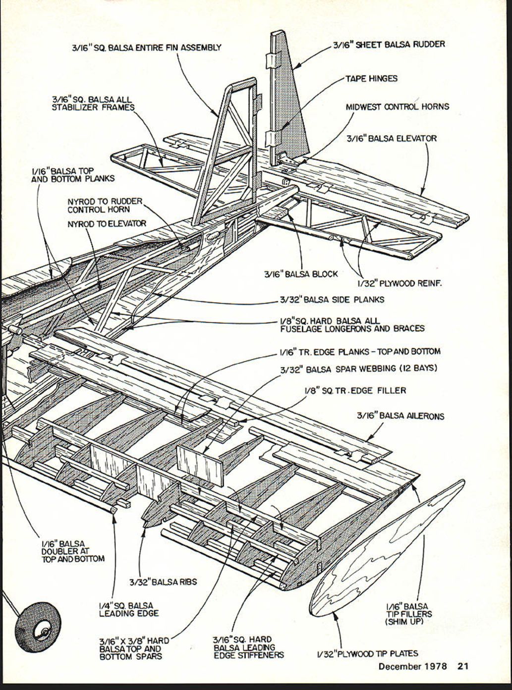
- 3/16" sq. balsa for entire fin assembly
- 3/16" sq. balsa for all stabilizer frames
- 1/16" balsa top and bottom planks
- Nyrod to rudder control horn
- Nyrod to elevator
- 3/16" sheet balsa rudder
- Tape hinges
- Midwest control horns
- 3/16" balsa elevator
- 3/16" balsa block
- 1/32" plywood reinforcement
- 3/32" balsa side planks
- 1/8" sq. hard balsa for all fuselage longerons and braces
- 1/16" trailing edge planks — top and bottom
- 3/32" balsa spar webbing (12 bays)
- 1/8" sq. trailing edge filler
- 3/16" balsa ailerons
- 1/16" balsa doubler at top and bottom
- 3/32" balsa ribs
- 1/4" sq. balsa leading edge
- 3/16" x 3/8" hard balsa top and bottom spars
- 3/16" sq. hard balsa leading edge stiffeners
- 1/16" balsa tip fillers (shim up)
- 1/32" plywood tip plates
The Fuselage
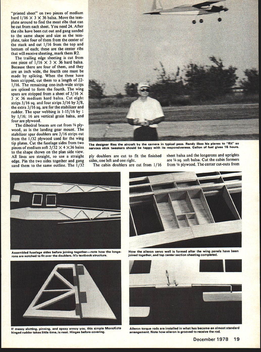
Epoxy the 1/32" plywood doublers to the forward part of the fuselage sides, making sure there are left and right sides with the plywood doublers to the inside. The cabin doublers are notched to fit over the ply doubler and glued in place. Longerons are notched to fit over the cabin doublers and glued; the uprights and stabilizer supports are added last. When all is dry, pin the two sides together again and sand the edges true and square.
Place one side over the side view on the plans and mark the location of the cabin formers. While the side is still flat on the plan, glue the cabin formers in their locations, using a square or right triangle to keep them square with the fuselage side. Be certain that the formers are where they belong—front in front, etc. When the glue has set, glue the other side on top of the formers and, using a square, make sure that the edges of both sides are square with each other front and back, top and bottom.
When all is dry, place the bottom of the fuselage on a flat work surface over the top view of the plan. Bring in the nose sides to the firewall and epoxy it in place, holding it with clamps, string, rubber bands or whatever works for you. Bring the tail together, beveling to fit, then gluing, being sure the stabilizer cut‑outs are parallel to the work surface. Locate the position of the landing gear mount and notch the bottom fuselage sides 1/16" so that, when the sheeting is added, the landing gear mount won't stick up above it. Glue in the mount and sheet the bottom with 1/16" balsa, cross grain.
Cut the exit holes for the outer nyrod and install the rods, using epoxy where they exit the fuselage side, and add bulkheads to the aft fuselage as shown to hold them in place. Epoxy the brass tube fuel and overflow lines through the firewall and the T‑nuts for the engine mount to the back of it. Install the fuel tank, using foam on the bottom and sides to wedge the tank into position, and a 3/16" balsa bulkhead behind it. Attach the fuel and overflow lines. Use the inner nyrod to bring the throttle through the firewall to the cabin and epoxy it into the firewall. Sheet the fuselage with 1/16" from the firewall to the tail.
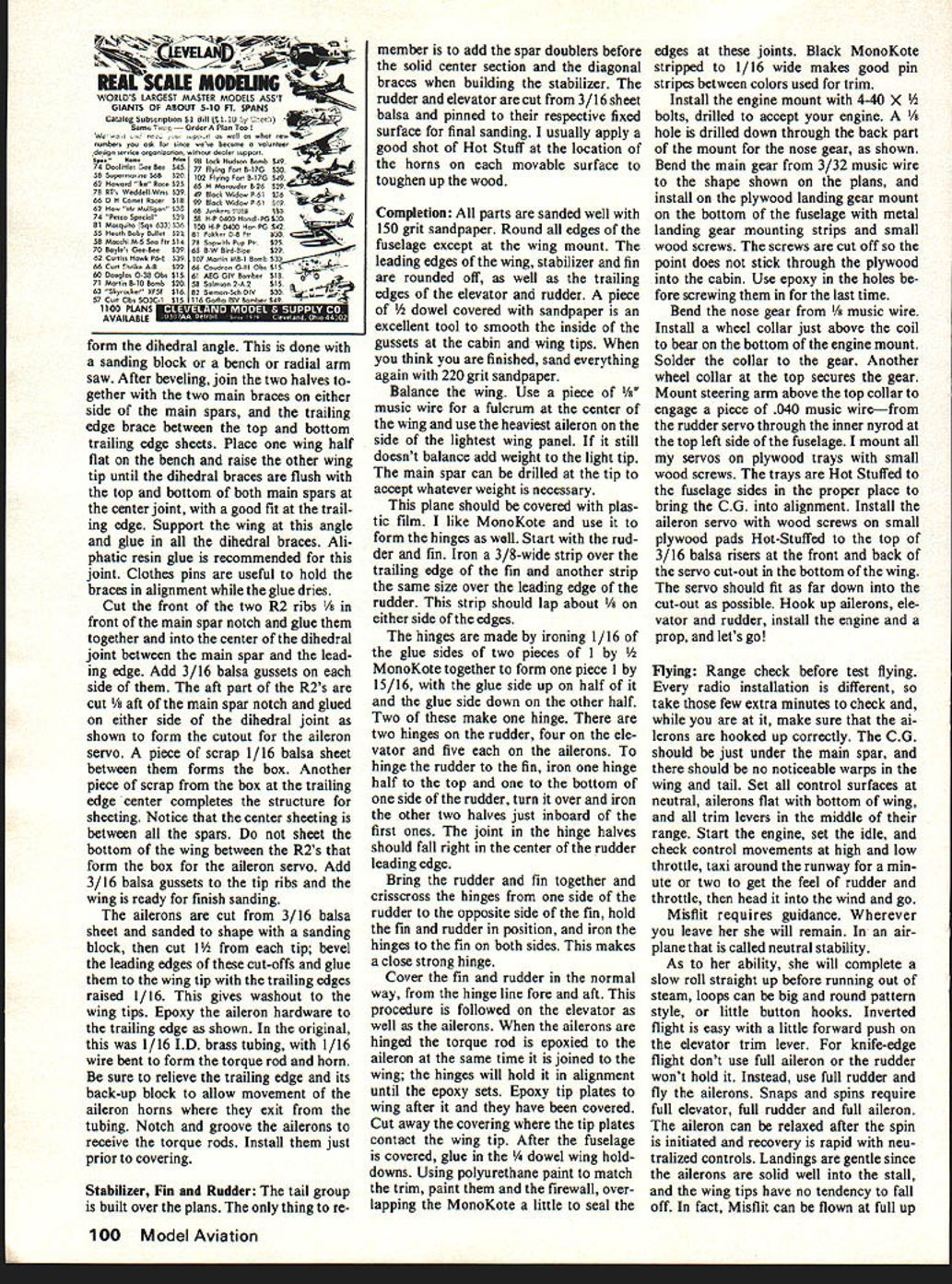
Install the forward cabin former. Cut a hole in this sheeting for the inner nyrod nose‑gear steering shown. Use epoxy and microballoons to install the nyrod, making sure that it extends well into the cabin. Complete the top sheeting, install the cabin gussets, and the fuselage is ready for final sanding.
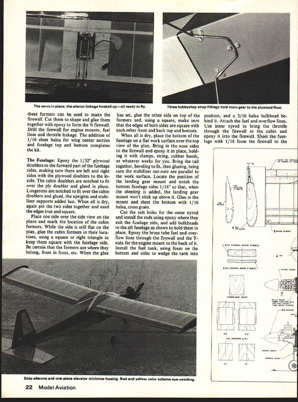
A simple MonoKote‑hinged rudder takes little time and looks neat; hinge before covering. Aileron torque rods are installed in what has become an almost‑standard arrangement. Note the aileron is grooved to receive the rod.
Wing
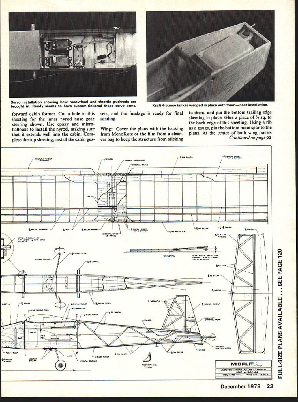
Cover the plans with the backing from MonoKote or the film from a cleaners' bag to keep the structure from sticking to them, and pin the bottom trailing edge sheeting in place. Glue a piece of 1/8" sq. to the back edge of this sheeting. Using a rib as a gauge, pin the bottom main spar to the plans. At the center of both wing panels where ribs R2 are located, pin a piece of scrap 1/16" sheet between the trailing edge and the main spar. This is to hold rib R2 up from the plans, so when the 1/16" bottom sheeting is added later it will be flush.
Glue the first regular rib near the center of the wing in place over the plan, and glue one of the plywood webs to it and the spar on its outboard side. The webbing makes an excellent spacer and assures that the ribs are perpendicular to the spar as well. Continue adding ribs and webs out to the tip; there is no web between the last few tip ribs. After all ribs are in place, glue in the top main spar. Be sure it is in good contact with the webs as well as the ribs.
Glue a plywood web inboard of the first regular rib installed near the center section, and slide on the first R2 and glue it in place. Glue the top front spar in place and bevel the 1/8" square at the trailing edge to receive the top trailing sheet and glue it in place. The other half of the wing is assembled in the same sequence.
When both wing halves have been assembled, bevel the spars, leading and trailing edges where they will be joined to form the dihedral angle. This is done with a sanding block or a bench or radial arm saw. After beveling, join the two halves together with the two main braces on either side of the main spars, and the trailing edge brace between the top and bottom trailing edge sheets. Place one wing half flat on the bench and raise the other wing tip until the dihedral braces are flush with the top and bottom of both main spars at the center joint, with a good fit at the trailing edge. Support the wing at this angle and glue in all the dihedral braces. Aliphatic resin glue is recommended for this joint. Clothespins are useful to hold the braces in alignment while the glue dries.
Cut the front of the two R2 ribs 1/8" in front of the main spar notch and glue them together and into the center of the dihedral joint between the main spar and the leading edge. Add 3/16" balsa gussets on each side of them. The aft part of the R2s are cut 3/8" aft of the main spar notch and glued on either side of the dihedral joint as shown to form the cutout for the aileron servo. A piece of scrap 1/16" balsa sheet between them forms the box. Another scrap piece at the trailing edge center completes the structure for sheeting. Notice that the center sheeting is between all the spars. Do not sheet the bottom of the wing between the R2s that form the box for the aileron servo. Add 3/16" balsa gussets to the tip ribs and the wing is ready for finish sanding.
The ailerons are cut from 3/16" balsa sheet and sanded to shape with a sanding block, then cut 1/2" from each tip; bevel the leading edges of these cut‑offs and glue them to the wing tip with the trailing edges raised 1/16". This gives washout to the wing tips. Epoxy the aileron hardware to the trailing edge as shown. In the original, this was 1/16" I.D. brass tubing, with 1/16" wire bent to form the torque rod and horn. Be sure to relieve the trailing edge and its backup block to allow movement of the aileron horns where they exit from the tubing. Notch and groove the ailerons to receive the torque rods. Install them just prior to covering.
Stabilizer, Fin and Rudder
The tail group is built over the plans. The only thing to remember is to add the spar doublers before the solid center section and the diagonal braces when building the stabilizer. The rudder and elevator are cut from 3/16" sheet balsa and pinned to their respective fixed surfaces for final sanding. I usually apply a good shot of Hot Stuff at the location of the horns on each movable surface to toughen up the wood.
Completion
All parts are sanded well with 150‑grit sandpaper. Round all edges of the fuselage except at the wing mount. The leading edges of the wing, stabilizer and fin are rounded off, as well as the trailing edges of the elevator and rudder. A piece of 1/2" dowel covered with sandpaper is an excellent tool to smooth the inside of the gussets at the cabin and wing tips. When you think you are finished, sand everything again with 220‑grit sandpaper.
Balance the wing. Use a piece of 1/8" music wire for a fulcrum at the center of the wing and use the heaviest aileron on the side of the lightest wing panel. If it still doesn't balance, add weight to the light tip. The main spar can be drilled at the tip to accept whatever weight is necessary.
This plane should be covered with plastic film. I like MonoKote and use it to form the hinges as well. Start with the rudder and fin. Iron a 3/8"‑wide strip over the trailing edge of the fin and another strip the same size over the leading edge of the rudder. This strip should lap about 1/8" on either side of the edges.
The hinges are made by ironing 1/16" of the glue sides of two pieces of 1" by 1/2" MonoKote together to form one piece 1" by 15/16", with the glue side up on half of it and the glue side down on the other half. Two of these make one hinge. There are two hinges on the rudder, four on the elevator and five on each aileron. To hinge the rudder to the fin, iron one hinge half to the top and one to the bottom of one side of the rudder, turn it over and iron the other two halves just inboard of the first ones. The joint in the hinge halves should fall right in the center of the rudder leading edge.
Bring the rudder and fin together and crisscross the hinges from one side of the rudder to the opposite side of the fin, hold the fin and rudder in position, and iron the hinges to the fin on both sides. This makes a close, strong hinge.
Cover the fin and rudder in the normal way, from the hinge line fore and aft. This procedure is followed on the elevator as well as the ailerons. When the ailerons are hinged the torque rod is epoxied to the aileron at the same time it is joined to the wing; the hinges will hold it in alignment until the epoxy sets. Epoxy tip plates to the wing after they are covered. Cut away the covering where the tip plates contact the wing tip. After the fuselage is covered, glue in the 1/4" dowel wing hold‑downs. Using polyurethane paint to match the trim, paint them and the firewall, overlapping the MonoKote a little to seal the edges at these joints. Black MonoKote stripped to 1/16" wide makes good pin‑strips between colors used for trim.
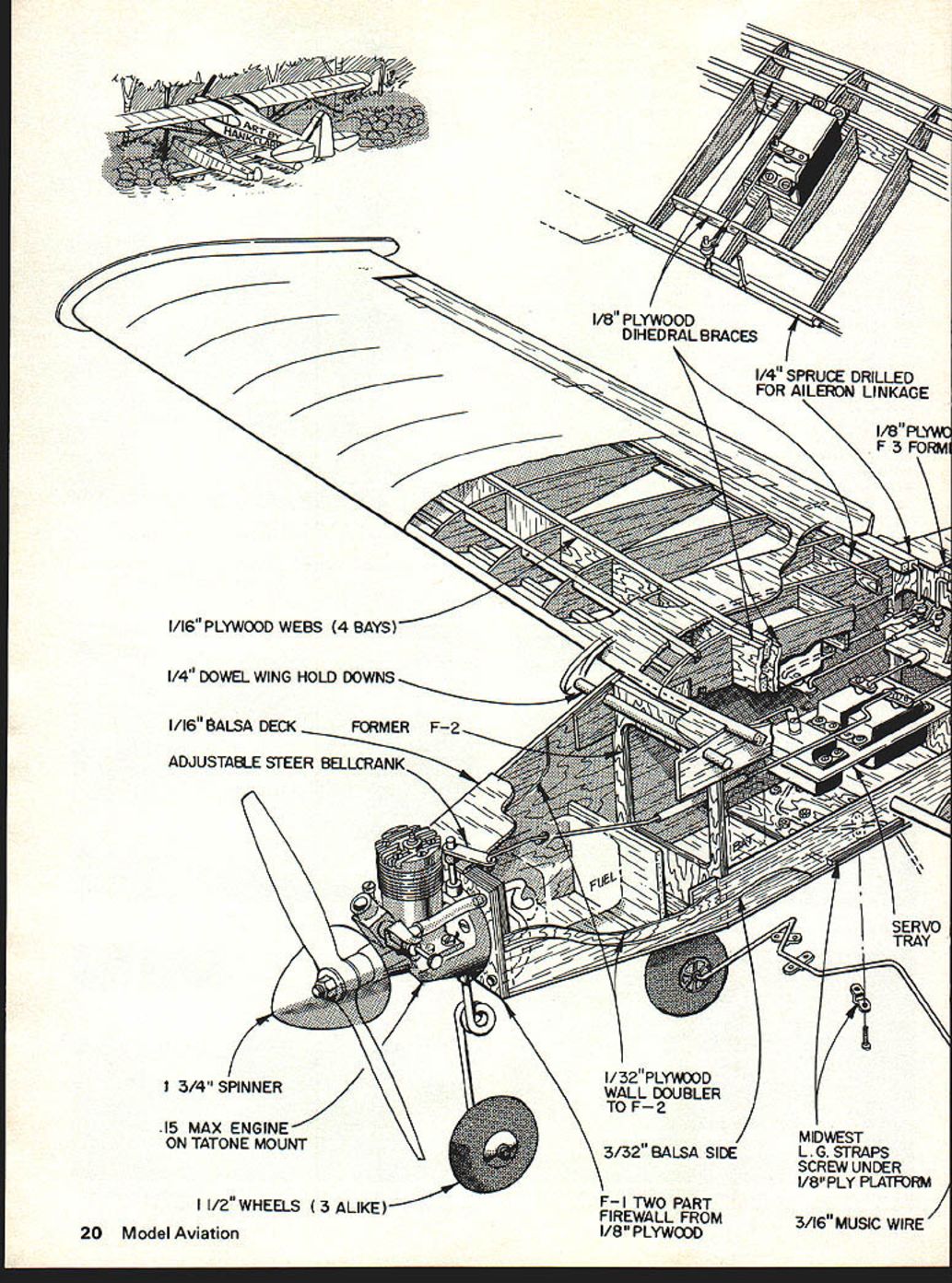
Install the engine mount with 4‑40 x 1/2" bolts, drilled to accept your engine. A 1/8" hole is drilled down through the back part of the mount for the nose gear, as shown. Bend the main gear from 3/32" music wire to the shape shown on the plans, and install on the plywood landing gear mount on the bottom of the fuselage with metal landing gear mounting strips and small wood screws. The screws are cut off so the point does not stick through the plywood into the cabin. Use epoxy in the holes before screwing them in for the last time.
Bend the nose gear from 1/8" music wire. Install a wheel collar just above the coil to bear on the bottom of the engine mount. Solder the collar to the gear. Another wheel collar at the top secures the gear. Mount the steering arm above the top collar to engage a piece of .040" music wire from the rudder servo through the inner nyrod at the top left side of the fuselage. I mount all my servos on plywood trays with small wood screws. The trays are Hot‑Stuffed to the fuselage sides in the proper place to bring the C.G. into alignment. Install the aileron servo with wood screws on small plywood pads Hot‑Stuffed to the top of 3/16" balsa risers at the front and back of the servo cut‑out in the bottom of the wing. The servo should fit as far down into the cut‑out as possible. Hook up ailerons, elevator and rudder, install the engine and a prop, and let's go!
Flying
Range check before test flying. Every radio installation is different, so take those few extra minutes to check and, while you are at it, make sure that the ailerons are hooked up correctly. The C.G. should be just under the main spar, and there should be no noticeable warps in the wing and tail. Set all control surfaces at neutral, ailerons flat with the bottom of the wing, and all trim levers in the middle of their range. Start the engine, set the idle, and check control movements at high and low throttle, taxi around the runway for a minute or two to get the feel of rudder and throttle, then head it into the wind and go.
Misflit requires guidance. Wherever you leave her she will remain. In an airplane that is called neutral stability.
As to her ability, she will complete a slow roll straight up before running out of steam; loops can be big and round (pattern style) or little button hooks. Inverted flight is easy with a little forward push on the elevator trim lever. For knife‑edge flight don't use full aileron or the rudder won't hold it. Instead, use full rudder and fly the ailerons. Snaps and spins require full elevator, full rudder and full aileron. The aileron can be relaxed after the spin is initiated and recovery is rapid with neutralized controls. Landings are gentle since the ailerons are solid well into the stall, and the wing tips have no tendency to drop. In fact, Misflit can be flown at full up elevator and just enough throttle to remain airborne and still answer to the ailerons.
A good .20 will enhance vertical performance but, other than that, is not worth the trouble. See you later—I'm going flitting.
Transcribed from original scans by AI. Minor OCR errors may remain.

