
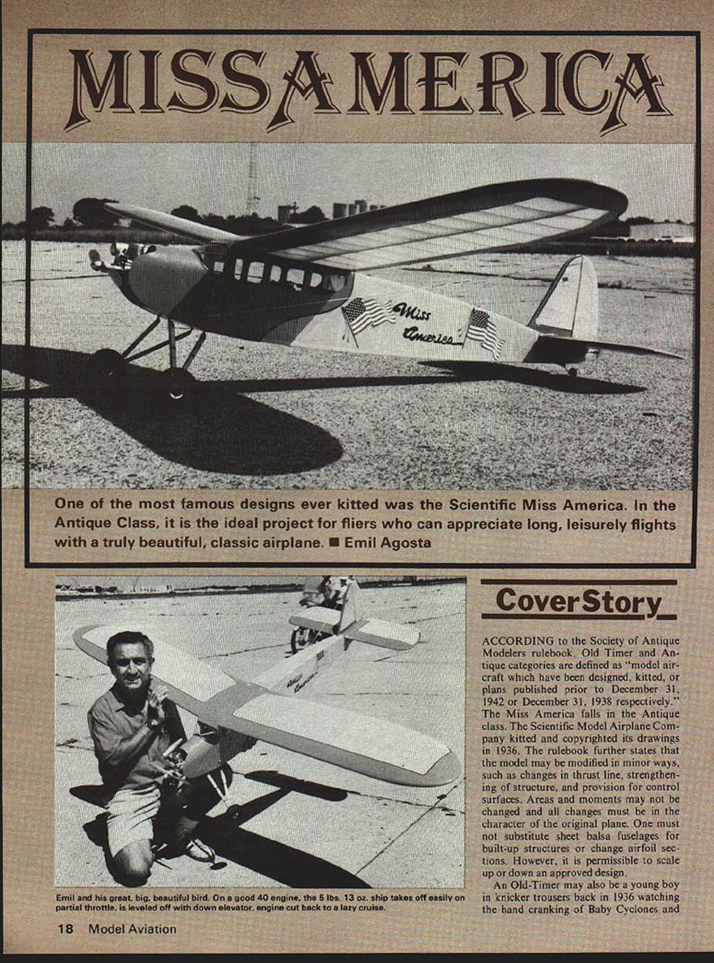
Miss America: Cover Story
ACCORDING to the Society of Antique Modelers rulebook, Old Timer and Antique categories are defined as "model aircraft which have been designed, kitted, or plans published prior to December 31, 1942 or December 31, 1938 respectively." The Miss America falls in the Antique class. The Scientific Model Airplane Company kitted and copyrighted its drawings in 1936. The rulebook further states that the model may be modified in minor ways, such as changes in thrust line, strengthening of structure, and provision for control surfaces. Areas and moments may not be changed and all changes must be in the character of the original plane. One must not substitute sheet balsa fuselages for built-up structures or change airfoil sections. However, it is permissible to scale up or down an approved design.
An Old-Timer may also be a young boy in knicker trousers back in 1936 watching the hand cranking of Baby Cyclones and Brown Junior engines with hand-carved propellers at Van Courtlandt Park, New York, with wonderment and desire to graduate from rubber-powered kits to an honest to goodness "gas job." To the boy, the gas job fliers were grown men, and it seemed like a millenium before he, too, could participate. Actually, the "grown men" were only in their late teens or early twenties!
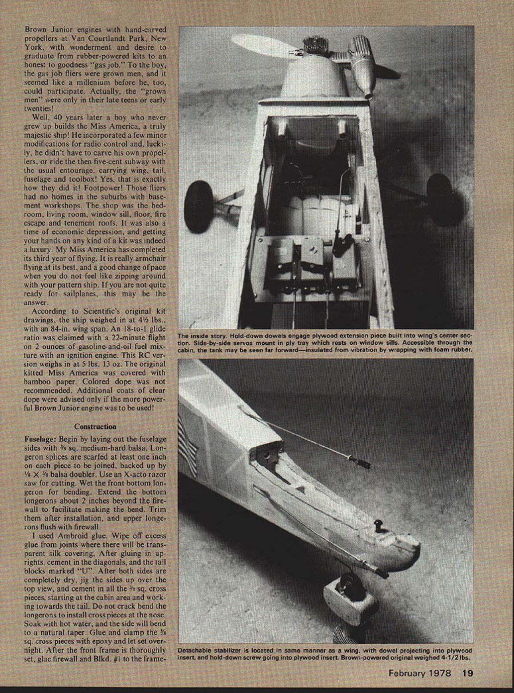
Well, 40 years later a boy who never grew up builds the Miss America, a truly majestic ship! He incorporated a few minor modifications for radio control and, luckily, he didn't have to carve his own propellers, or ride the then five-cent subway with the usual entourage, carrying wing, tail, fuselage and toolbox! Yes, that is exactly how they did it! Footpower! Those fliers had no homes in the suburbs with basement workshops. The shop was the bedroom, living room, window sill, floor, fire escape and tenement roofs. It was also a time of economic depression, and getting your hands on any kind of a kit was indeed a luxury. My Miss America has completed its third year of flying. It is really armchair flying at its best, and a good change of pace when you do not feel like zipping around with your pattern ship. If you are not quite ready for sailplanes, this may be the answer.
According to Scientific's original kit drawings, the ship weighed in at 4-1/2 lbs., with an 84-in. wing span. An 18-to-1 glide ratio was claimed with a 22-minute flight on 2 ounces of gasoline-and-oil fuel mixture with an ignition engine. This RC version weighs in at 5 lbs. 13 oz. The original kitted Miss America was covered with bamboo paper. Colored dope was not recommended. Additional coats of clear dope were advised only if the more powerful Brown Junior engine was to be used!
Construction
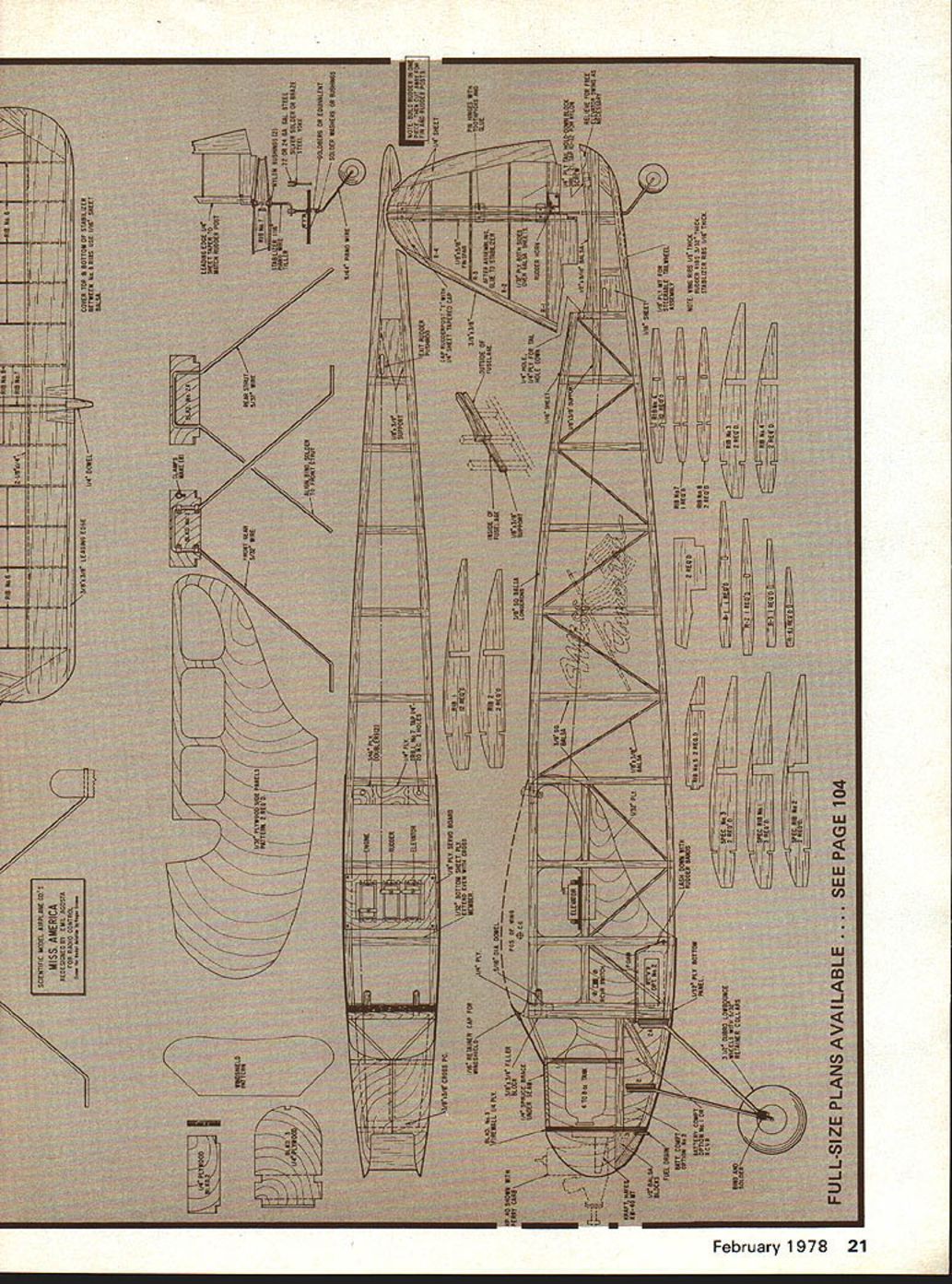
Fuselage: Begin by laying out the fuselage sides with 3/8 sq. medium-hard balsa. Longeron splices are scarfed at least one inch on each piece to be joined, backed up by 1/8 x 3/8 balsa doubler. Use an X-acto razor saw for cutting. Wet the front bottom longeron for bending. Extend the bottom longerons about 2 inches beyond the firewall to facilitate making the bend. Trim them after installation, and upper longerons flush with firewall.
I used Ambroid glue. Wipe off excess glue from joints where there will be transparent silk covering. After gluing in uprights, cement in the diagonals, and the tail blocks marked "U". After both sides are completely dry, jig the sides up over the top view, and cement in all the 3/8 sq. cross pieces, starting at the cabin area and working towards the tail. Do not crack bend the longerons to install cross pieces at the nose. Soak with hot water, and the side will bend to a natural taper. Glue and clamp the 3/8 sq. cross pieces with epoxy and let set overnight. After the front frame is thoroughly set, glue firewall and Blkd. #1 to the frame. Use epoxy glue. Glue in doubler brace between firewall and Blkd. #1.
Bend landing gear struts, and assemble with sheetmetal clamps on to Blkds. #2 and #2A. Bind and solder at axle location. Align and glue to fuselage. Shape and attach landing gear fairings, and wrap with black thread. Locate the thrust line, engine mount holes, and install 6-32 T-Nuts on firewall. Secure them with a dab of epoxy. Locate and drill the fuel tank feed and vent lines.
Make a heavy brown paper pattern of the 1/32 plywood sheeting, slightly larger to allow for trimming and slight misalignment. Cut the windows 1/8 in. larger to allow gluing surface on the inside of the fuselage. This gives a cleaner appearance.
When the plywood sheeting is ready for assembly, spread a bead of Franklin Tite-Bond over the structure which the sheeting will cover, and cement down with fuselage on its side. Do not attempt to curve the sheeting around the firewall area at this time. Place weights over the sheeting to achieve maximum bonding. When both sides are set, gradually bend both at the center of the firewall, and mark seam on doubler brace. This is a cut and fit procedure and should be done accurately. When you are satisfied with the fit, glue both pieces down to firewall and Blkd. #1.
Fasten down with long strips of masking tape until glue is dry. This method insures that the sheeting will conform with contour of firewall, and seam will make good bond to doubler brace.
Trim excess plywood skin flush with structure, and glue in 1/8-in. balsa cheek blocks. Finish off bottom of fuselage with 1/32 plywood, carefully notching around landing gear, and curve up around nose, gluing skin to bottom of the cheek blocks. Trim bottom skin flush with fuselage sides.
Glue in 1/8 x 3/8 supports at tail and wing, mounting plywood pieces in cabin area, but do not drill holes at this time. Do not glue in 3/8 x 3/8 balsa filler block, or tail tie-down screw block. Glue in the stabilizer saddles, and temporarily spot glue the 1/4 in. plywood bulkhead for stabilizer plug-in dowel. Install sheeted areas for elevator and rudder pushrod exit guides.
Wing: Note that the wing has a center section with spars joining it at section "H". The spars and sections must be cut accurately and assembled on the plan. Glue up one spar, reverse it on the plan, and assemble other spar. Note that spars begin to taper about 6-1/4 in. from each end. The dihedral is built-in by this method of construction. Add center brace "S" with Titebond glue. Cut out wing tip pieces and lay aside. Jig up spar over plan.
Small squared-off pine blocks with wire brads will hold spar 90 degrees to working surface. Center-section ribs are assembled 90 degrees to the cabin area. Remaining ribs are assembled, with a good fit into notches at trailing edge. Leading edge must be accurately cut at the splice before assembling to ribs. Assemble wing tip pieces, FULL-SIZE PLANS AVAILABLE — SEE PAGE 104 and align with leading edge, then glue them in. Complete wing by adding and carefully splicing the 1/4 x 1/4 stringers, and balsa sheeting. Add small false ribs to top and bottom of special Rib #1 to provide good gluing surface for butt-joining of sheeting.
Complete assembly of one wing panel as much as possible while jigged up on plan, before commencing assembly of other panel. Center section is sheeted with 1/32 plywood. Do not crack plywood sheeting at center section! Clamping pressure at dihedral joint will insure more than adequate strength with the plywood sheeting acting as a gusset.
Fair and streamline entire wing and sand smooth. The wing is indeed a beautiful piece of classic model construction and the builder should pay attention to the most minute discrepancy which may mar a perfectly good covering job. This is one airplane where fillers and spackling compound will be of little help. However, some filling will be needed to fair in the windshield at the sides of the fuselage.
Install the wing hold-down tongue. With the point of a razor saw, cut a 3-1/4-in. long slot directly behind leading edge at center section bottom of wing. Part of center section rib will be cut away. Tongue should touch top of center section plywood sheeting. Make sure slot is centered and that tongue fits flat against leading edge. Glue it in with Sears Filled Epoxy cement. The strength of this glue is unbelievable! Align wing on fuselage and temporarily hold down with masking tape. From front of cabin, drill two pilot holes for the dowel hold-down holes, then open 1/4-in. tongue in wing, thus assuring perfect dowel alignment. Temporarily place dowels in place, without glue! Spot, drill and tap 1/4-20 nc holes for wing hold-down. Epoxy dowels in place. Glue the 3/8 x 3/4 filler block in place and install window posts.
Stabilizer
Construction is simple. Ribs are symmetrical in airfoil, therefore, trailing and leading edges must be blocked up. Make the elevators from 1/4 in. trailing edge stock. Gap between elevators is determined by amount of rudder throw and up-elevator. A large elevator surface is not necessary with this type of ship. The Clark Y airfoil needs no rotation for lift; use throttle for climbing to altitude. With full up-elevator, the ship will loop.
Trailing edge is 1/4 x 3/8 balsa, notched for ribs. Before sheeting center section, glue in 1/8 in. plywood hold-down block. Fair with scrap balsa, and complete sheeting. Drill 3/16 hole in stabilizer for the 10-32 hold-down screw. Counterbore away all balsa sheeting until the head of the screw sits flat on the plywood. Sand and streamline stabilizer, and align on fuselage.
Locate hole on leading edge for 1/4 in. hold-down dowel, glue in with Sears Epoxy. Locate receiving hole on plywood bulkhead by placing small piece of carbon paper between dowel and plywood bulkhead. Press stabilizer forward, and dowel will transfer proper location for 1/4 in. hole. Break loose the 1/4 in. plywood bulkhead, drill and replace with epoxy. With stabilizer in place, mark and locate 1/4 in. plywood plate on stabilizer saddle. Glue in place, drill .221, and tap it out 10-32.
Cover stabilizer and elevator before assembling fin. Hinge elevators, and peg with toothpicks dipped in glue. Relieve sufficient wood from the stabilizer saddle for clearance and movement of elevators.
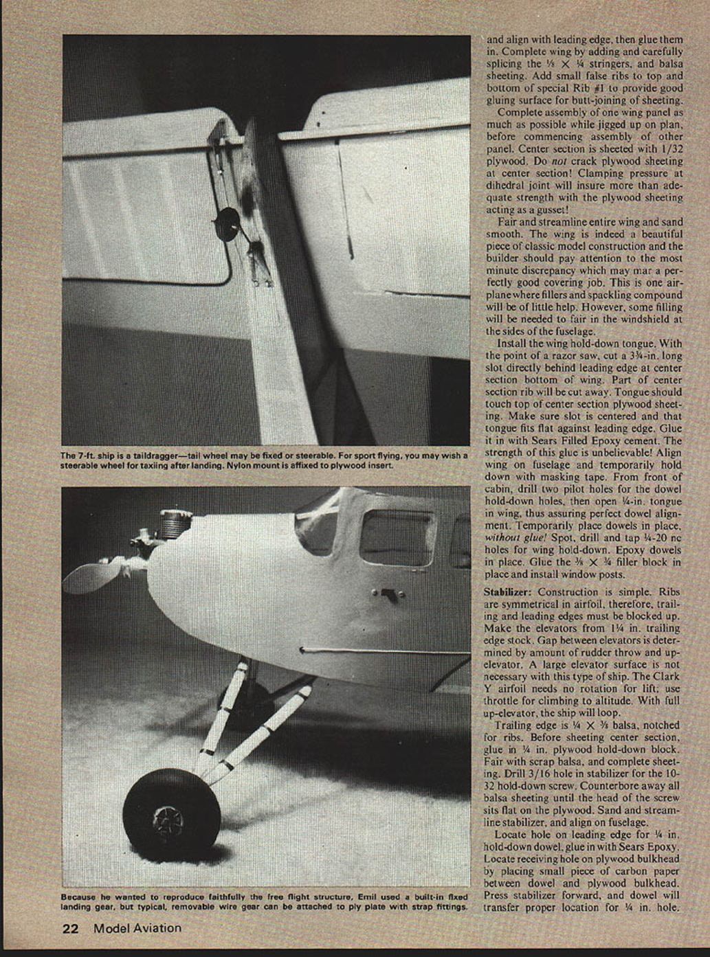
Fin and Rudder:
Build rudder and fin in one piece, then cut and trim for fin and rudder posts. Cover and assemble fin while on to the stabilizer. Decide which tail wheel system to use: fixed or steerable. Under SAM rules, plane must land with power off. For sport flying, builder may want to land with power on and be able to taxi. If you go the steerable route, first make tiller arm bend which attaches to the rudder post. Make bend which engages tailwheel yoke after rudder is covered, hinged, and piano wire passed through stabilizer. The yoke arrangement on wheel is simple. Tiller arm simply slides into yoke slot, at same time locating stabilizer plug-in dowel. Tiller may be insulated with shrink tubing to prevent radio noise.
Covering:
Use heavy-weight silk for covering. You need three yards. This is accomplished by using 3-ft. sections on wings from center section special Rib #1, to wingtip Rib #5, allowing 1/2 in. lap at these points. When sprayed with water, a little more gluing surface is gained. Do not cut silk panels with more than a 3/4 in. excess. Stingy? You bet, today's prices!
Before commencing to cover, inspect for imperfections, glue joints, and thoroughly fine sand. Break all sharp edges with #280 or #320 silicon carbide paper. Longerons should be only slightly rounded. Apply about four coats to frame, lightly sanding each coat only in areas that come in contact with silk. I used yellow silk, clear doped with a brush until the weave was filled. Use very thin mixture (at least 50-50) to prevent spotty build-up of dope. Entire ship is sprayed with clear dope, slightly tinted with 1/2 pint of yellow dope to the quart. This process gives yellow silk some depth in color while retaining transparency.
Windshield:
Cut from fairly heavy clear plastic, rather than thin, flexible material. Fatigue cracks have developed in a radial pattern due to vibrations transmitted via firewall. New, heavier windshield was installed with Deacon liquid-rubber cement. It is superior to anything used for this purpose thus far.
Pay special attention to where windshield meets fairing. Modified windshield has pleasing, rounded look. Fit it carefully and sand edges with 400 silicon carbide paper. Rough edges invite ugly, multiple fatigue cracks. Fit windshield and hold down with masking tape for fitting and marking. Some filling and fairing will be needed at fuselage sides. Install side windows with rectangular pieces from the inside of fuselage. Trim paint as desired, separating colors with 1/8 in. trim tape. Seal tape with polyurethane varnish, otherwise hot fuel will eventually peel it off.
The Miss America was color trimmed in bright orange. American flag decals are available at Woolworth's. They must be varnished down for fuel proofing. The name "Miss America" was painted with a very unsteady hand. Perhaps airbrushing through a stencil made from decorator's contact paper would be easier.
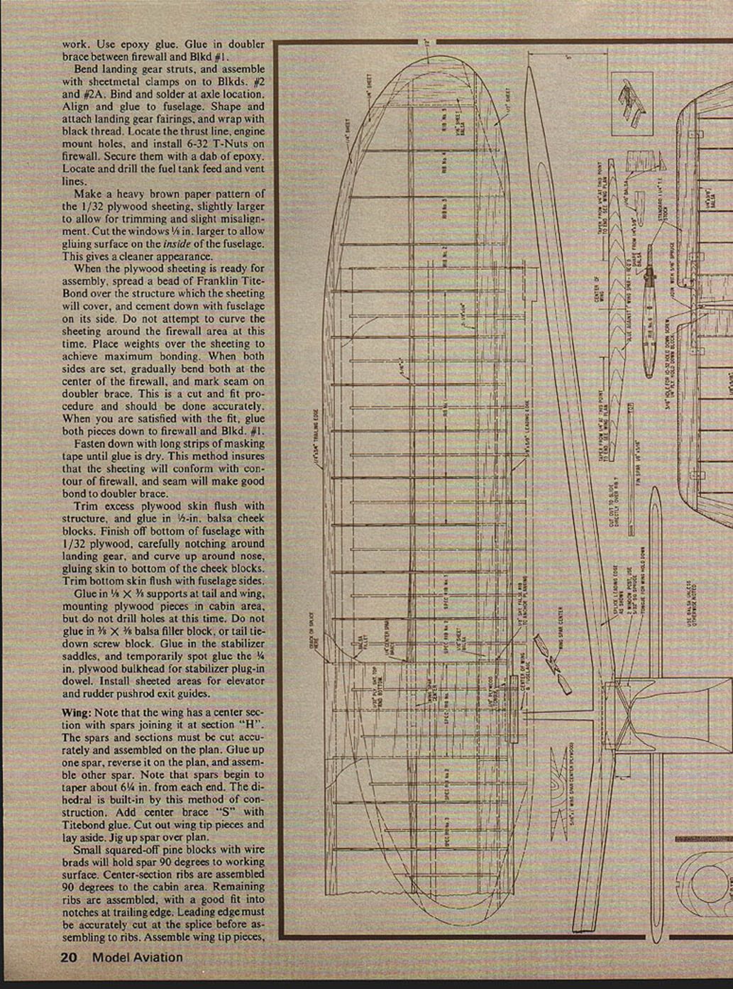
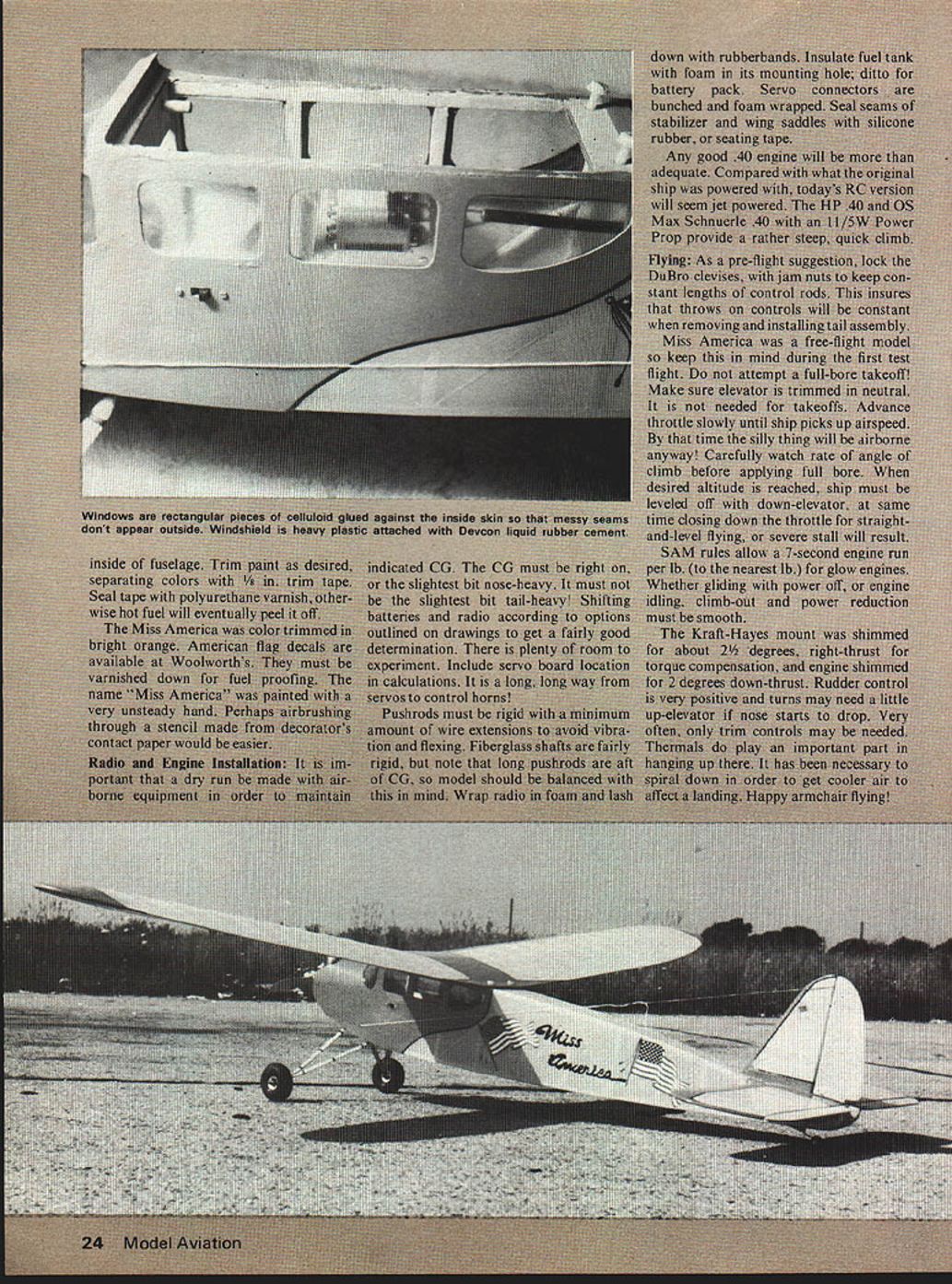
Radio and Engine Installation: It is important that a dry run be made with airborne equipment in order to maintain indicated CG. The CG must be right on, or the slightest bit nose-heavy. It must not be the slightest bit tail-heavy! Shifting batteries and radio according to options outlined on drawings to get a fairly good determination. There is plenty of room to experiment. Include servo board location in calculations. It is a long, long way from servos to control horns!
Pushrods must be rigid with a minimum amount of wire extensions to avoid vibration and flexing. Fiberglass shafts are fairly rigid, but note that long pushrods are aft of CG, so model should be balanced with this in mind. Wrap radio in foam and lash down with rubberbands. Insulate fuel tank with foam in its mounting hole; ditto for battery pack. Servo connectors are bunched and foam wrapped. Seal seams of stabilizer and wing saddles with silicone rubber, or seating tape.
Any good .40 engine will be more than adequate. Compared with what the original ship was powered with, today's RC version will seem jet powered. The HP 40 and OS Max Schnuerle .40 with an 11/5W Power Prop provide a rather steep, quick climb.
Flying: As a pre-flight suggestion, lock the DuBro clevises, with jam nuts to keep constant lengths of control rods. This insures that throws on controls will be constant when removing and installing tail assembly. Miss America was a free-flight model so keep this in mind during the first test flight. Do not attempt a full-bore takeoff! Make sure elevator is trimmed in neutral. It is not needed for takeoffs. Advance throttle slowly until ship picks up airspeed. By that time the silly thing will be airborne anyway! Carefully watch rate of angle of climb before applying full bore. When desired altitude is reached, ship must be leveled off with down-elevator; at same time closing down the throttle for straight-and-level flying, or severe stall will result.
SAM rules allow a 7-second engine run per lb. (to the nearest lb.) for glow engines. Whether gliding with power off, or engine idling, climb-out and power reduction must be smooth.
The Kraft-Hayes mount was shimmed for about 2-1/4 degrees right-thrust for torque compensation, and engine shimmed for 2 degrees down-thrust. Rudder control is very positive and turns may need a little up-elevator if nose starts to drop. Very often, only trim controls may be needed. Thermals do play an important part in hanging up there. It has been necessary to spiral down in order to get cooler air to affect a landing. Happy armchair flying!
Transcribed from original scans by AI. Minor OCR errors may remain.

