
Miss America for A Texaco
Norm Rosenstock
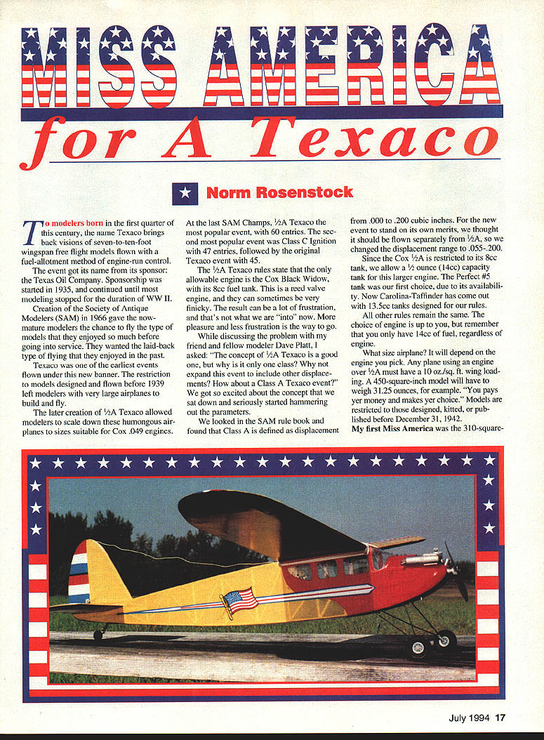
To modelers born in the first quarter of this century, the name Texaco brings back visions of seven- to ten-foot wingspan free-flight models flown with a fuel-allotment method of engine-run control.
The event got its name from its sponsor, the Texas Oil Company. Sponsorship was started in 1935 and continued until most modeling stopped for the duration of WWII.
Creation of the Society of Antique Modelers (SAM) in 1966 gave the now-mature modelers the chance to fly the type of models they enjoyed before going into service. They wanted the laid-back type of flying from the past.
Texaco was one of the earliest events flown under the new banner. The restriction to models designed and flown before 1939 left modelers with very large airplanes to build and fly. The later creation of 1/2A Texaco allowed modelers to scale down these humongous airplanes to sizes suitable for Cox .049 engines.
At the last SAM Champs, 1/2A Texaco was the most popular event, with 60 entries. The second most popular event was Class C Ignition with 47 entries, followed by the original Texaco event with 45.
The 1/2A Texaco rules state that the only allowable engine is the Cox Black Widow, with its 8 cc fuel tank. This is a reed-valve engine, and they can sometimes be very finicky. The result can be a lot of frustration, and that's not what we are "into" now. More pleasure and less frustration is the way to go.
While discussing the problem with my friend and fellow modeler Dave Platt, I asked, "The concept of 1/2A Texaco is a good one, but why is it only one class? Why not expand this event to include other displacements? How about a Class A Texaco event?" We got so excited about the concept that we sat down and seriously started hammering out the parameters.
We looked in the SAM rule book and found that Class A is defined as displacement from .000 to .200 cubic inches. For the new event to stand on its own merits, we thought it should be flown separately from 1/2A, so we changed the displacement range to .055–.200.
Since the Cox 1/2A is restricted to its 8 cc tank, we allow a 1/2 ounce (14 cc) capacity tank for this larger engine. The Perfect No. 5 tank was our first choice, due to its availability. Now Carolina-Taffinder has come out with 13.5 cc tanks designed for our rules. All other rules remain the same. The choice of engine is up to you, but remember that you only have 14 cc of fuel, regardless of engine.
What size airplane? It will depend on the engine you pick. Any plane using an engine over 1/2A must have a 10 oz/sq ft wing loading. A 450-square-inch model will have to weigh 31.25 ounces, for example. "You pays yer money and makes yer choice." Models are restricted to those designed, kitted, or published before December 31, 1942.
My first Miss America was the 310-square-inch 1/2A version by Doc Mathews, published many years ago in Model Aviation. As a kid I wanted to build one but could not afford the $4.95 for the kit (it was the full-sized seven-foot model). I enjoyed flying the 1/2A model for many years, and when I started flying it in SAM meets, I started to win contests.
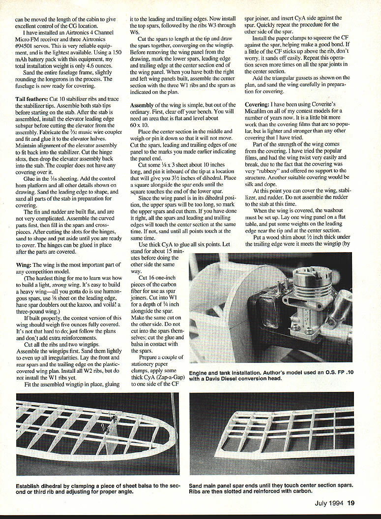
The excellent flight characteristics of this model led me to build a 600-square-inch version, powered with an ancient SuperTigre .15 diesel. I flew that plane for a number of years. One day I bought an O.S. FP .10 and got a Davis Diesel conversion head for the engine. After breaking in the engine on glow I installed the diesel head and liked the result so much that I scaled the Miss America to 500 square inches — a winning combination.
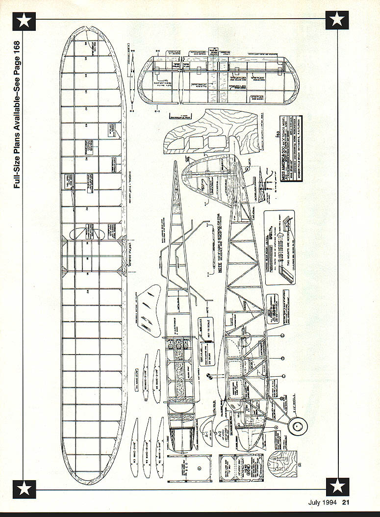
CONSTRUCTION
This model can be built as an A Texaco contest model or as a sport model.
- As a contest model it should weigh 35 ounces and should be powered with an .08 to .12 displacement engine.
- As a sport model it could weigh whatever you want, but I suggest no larger than a .15 glow engine with an overall weight no more than 45–50 ounces.
The only difference in construction is in the wing. The plans indicate the choice of wood: 3/32 x 1/8 spars are used for the contest version; 3/32 x 1/4 spars for the sport version. Note the front spars are spruce and the rear are balsa. The heavier spars for the sport version are due to the assumed increased weight and power.
Materials
- All glue used in the construction of this model is cyanoacrylate (CyA). I use Zap brand for its consistent quality. I use Zap for the fuselage frame and Zap-A-Gap (the thick stuff) for gluing the firewall, the 1/8" plywood doubler, and anywhere that has broad gluing surfaces.
- The balsa used in the construction of this model should be contest grade (four-to-six-pound density) wood.
- You will also need carbon fiber; get yourself a three-foot length of .007 x 1/4" epoxy laminate. I've been using Bob Violett's stuff.
Fuselage
The fuselage construction is very standard for this type of model. Pick out four longerons; look for uniformity and firmer (8–10 lb) density wood.
I usually buy plastic drop cloth (about 3 mil) and cut it into sheets the size I need for building. Cut a piece long enough to cover the fuselage three times the height needed. Start covering the fuselage drawings, letting the excess width hang down in front on the workbench. Use steel straight pins about 1 1/4" long to capture the longerons on the plans (never stick pins through the longerons). After cutting and inserting the uprights, hit the joints with thin CyA. When the fuselage side is complete, use a pair of wire-cutting pliers to cut off the pin heads.
Drape the end of the plastic that is hanging off the front of the bench over the top of the fuselage side, and gently press the plastic down over the newly headless pins until it covers the first fuselage side.
Add the new longerons, using the pins as a guide, and build the second side onto the first. After gluing all joints, lift off the two sides and let them air dry for about half an hour.
Use a large sanding block to lightly sand both sides to even out bumps and unevenness caused by the glue, then lay the two sides bottom-to-bottom on the table. Now prepare the carbon-fiber pieces and glue them in place as shown on the plans. I use .007 x 1/4" carbon fiber cut to one-inch lengths. Remember, the carbon fiber is only glued on the inside of the fuselage frame.
After assembling the sides, make sure that the fuselage is straight, and glue in place.
Prepare the firewall by drilling the engine mount holes. I use T-nuts (blind nuts) so that I can remove the mount. Glue the firewall and cheek blocks in place.
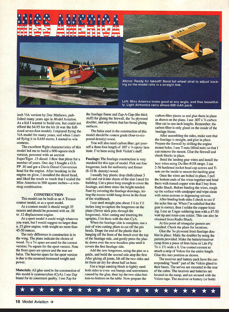
Bend the landing gear wires and install the bent wires using Du-Bro #158 straps. I use 2-56 hardened socket-head cap screws and T-nuts on the inside to mount the landing gear.
Once the wires are bolted in place, put the bottom ends of the wires together and bind them with tinned copper wire that I buy from Radio Shack. Before binding the wires, rough up the surface with sandpaper and wipe clean with some acetone or degreasing solvent.
After binding both sides check to see if the axles line up. When satisfied that they are even, solder the copper binding. I use an Ungar soldering iron with a 47–50 watt tip and rosin-core solder. This can also be obtained from Radio Shack.
At this point all triangular gussets are installed. Check the plans for locations.
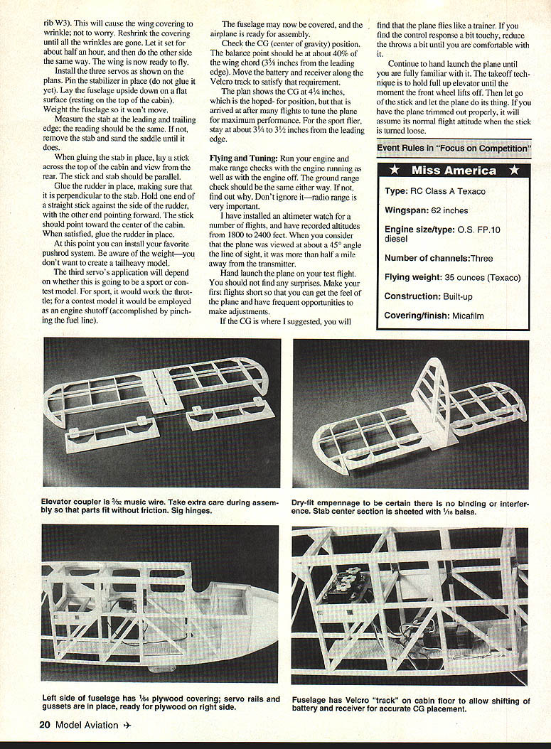
Glue the 1/8" plywood front fuselage doubler in place. Make the doubler up using the pattern provided. Make the battery/receiver tray from a piece of firm balsa or Lite Ply, 3/32" x 1 1/2" x 8". Use contact cement to attach a strip of Velcro for the entire length. Glue this into position as shown.
The receiver and battery pack have the corresponding "hook" part of the Velcro glued to their bases. The servos are mounted to the rear of the cabin. The receiver and batteries are located on the ramp and are secured with the Velcro tape. The receiver or battery (or both) can be moved the length of the cabin to give excellent control of the CG location.
I have installed an Airtronics 4-channel Micro FM receiver and three Airtronics #94501 servos. This is very reliable equipment, and is the lightest available. Using a 150 mAh battery pack with this equipment, my total installation weight is only 4.6 ounces.
Sand the entire fuselage frame, slightly rounding the longerons in the process. The fuselage is now ready for covering.
Tail feathers
Cut 10 stabilizer ribs and trace the stabilizer tips. Assemble both stab tips before starting on the stab. After the stab is assembled, install the elevator leading-edge sub-spar before cutting the elevator from the assembly. Fabricate the 3/32" music-wire coupler and fit and glue it to the elevator halves. Maintain alignment of the elevator assembly to fit back into the stabilizer. Cut the hinge slots, then drop the elevator assembly back into the stab. The coupler does not have any covering over it.
Glue the 1/16" sheeting. Add the control horn platform and all other details shown on the drawing. Sand the leading edge to shape, and sand all parts of the stab in preparation for covering.
The fin and rudder are built flat and are not very complicated. Assemble the curved parts first, then fill in the spars and cross-pieces. After cutting the slots for the hinges, sand to shape and put aside until you are ready to cover. The hinges can be glued in place after the parts are covered.
Wing
The wing is the most important part of any competition model.
(The hardest thing for me to learn was how to build a tight, strong wing. It's easy to build a heavy wing — all you gotta do is use humongous spars, use 1/8" sheet on the leading edge, have spar doublers out the kazoo, and voila! a three-pound wing.)
If built properly, the contest version of this wing should weigh five ounces fully covered. It's not that hard to do; just follow the plans and don't add extra reinforcements.
Cut all the ribs and two wingtips. Assemble the wingtips first. Sand them lightly to even up all irregularities. Lay the front and rear spars and the trailing edge on the plastic-covered wing plan. Install all W2 ribs, but do not install the W1 ribs yet.
Fit the assembled wingtip in place, gluing it to the leading and trailing edges. Now install the top spars, followed by the ribs W3 through W6.
Cut the spars to length at the tip and draw the spars together, converging on the wingtip. Before removing the wing panel from the drawing, mark the lower spars, leading edge, and trailing edge at the center-section end of the wing panel. When you have both the right and left wing panels built, assemble the center section with the three W1 ribs and the spars as indicated on the plan.
Assembly of the wing is simple, but out of the ordinary. First, clear off your bench. You will need an area that is flat and level about 60" x 10".
Place the center section in the middle and weigh or pin it down so that it will not move. Cut the spars, leading, and trailing edges of one panel to the marks you made earlier indicating the panel end.
Cut some 1/4" x 3" sheet about 10 inches long, and pin it inboard of the tip at a location that will give you 3 1/2" of dihedral. Place a square alongside the spar ends until the square touches the end of the lower spar.
Since the wing panel is in its dihedral position, the upper spars will be too long, so mark the upper spars and cut them. If you have done it right, all the spars and leading and trailing edges will touch the center section at the same time. If not, sand until all points touch at the same time.
Use thick CyA to glue all six points. Let stand for about 15 minutes before doing the other side the same way.
Cut 16 one-inch pieces of the carbon fiber for use as spar joiners. Cut into W1 for a depth of 1/4" alongside the spar. Make the same cut on the other side. Do not cut into the spars themselves; cut the glue and balsa in contact with the spars.
Prepare a couple of stationery paper clamps, apply some thick CyA (Zap-A-Gap) to one side of the CF spar joiner, and insert CyA side against the spar. Quickly repeat the procedure for the other side of the spar.
Install the paper clamps to squeeze the CF against the spar, helping make a good bond. If a little of the CF sticks up above the rib, don't worry, it sands off easily. Repeat this operation seven more times on all the spar joints in the center section.
Add the triangular gussets as shown on the plan, and sand the wing carefully in preparation for covering.
Covering
I have been using Coverite's Micafilm on all of my contest models for a number of years now. It is a little bit more work than the covering films that are so popular, but is lighter and stronger than any other covering that I have tried.
Part of the strength of the wing comes from the covering. I have tried the popular films and had the wing twist very easily and break, due to the fact that the covering was "rubbery" and offered no support to the structure. Another suitable covering would be silk and dope.
At this point you can cover the wing, stabilizer, and rudder. Do not assemble the rudder to the stab at this time.
When the wing is covered, the washout must be set up. Lay one wing panel on a flat table and put some weights on the leading edge near the tip and at the center section.
Put a wood shim about 1/2" thick under the trailing edge where it meets the wingtip (by rib W3). This will cause the wing covering to wrinkle; not to worry. Reshrink the covering until all the wrinkles are gone. Let it set for about half an hour, and then do the other side the same way. The wing is now ready to fly.
Install the three servos as shown on the plans. Pin the stabilizer in place (do not glue it yet). Lay the fuselage upside down on a flat surface (resting on the top of the cabin). Weight the fuselage so it won't move.
Measure the stab at the leading and trailing edge; the reading should be the same. If not, remove the stab and sand the saddle until it does.
When gluing the stab in place, lay a stick across the top of the cabin and view from the rear. The stick and stab should be parallel.
Glue the rudder in place, making sure that it is perpendicular to the stab. Hold one end of a straight stick against the side of the rudder, with the other end pointing forward. The stick should point toward the center of the cabin. When satisfied, glue the rudder in place.
At this point you can install your favorite pushrod system. Be aware of the weight—you don't want to create a tail-heavy model.
The third servo's application will depend on whether this is going to be a sport or contest model. For sport, it would work the throttle; for a contest model it would be employed as an engine shutoff (accomplished by pinching the fuel line).
The fuselage may now be covered, and the airplane is ready for assembly.
Check the CG (center of gravity) position. The balance point should be at about 40% of the wing chord — roughly 3 1/4" to 4 1/4" aft of the leading edge depending on setup. Move the battery and receiver along the Velcro track to satisfy that requirement.
The plan shows the CG at 4 1/4", which is the hoped-for position after many flights to tune the plane for maximum performance. For the sport flier, stay at about 3 1/4" to 3 1/2" from the leading edge.
FLYING AND TUNING
Run your engine and make range checks with the engine running as well as with the engine off. The ground range check should be the same either way. If not, find out why. Don't ignore it—radio range is very important.
I have installed an altimeter watch for a number of flights and have recorded altitudes from 1,800 to 2,400 feet. When you consider that the plane was viewed at about a 45° angle to the line of sight, it was more than half a mile away from the transmitter.
Hand-launch the plane on your test flight. You should not find any surprises. Make your first flights short so that you can get the feel of the plane and have frequent opportunities to make adjustments.
If the CG is where I suggested, you will find that the plane flies like a trainer. If you find the control response a bit touchy, reduce the throws a bit until you are comfortable with it.
Continue to hand-launch the plane until you are fully familiar with it. The takeoff technique is to hold full up elevator until the moment the front wheel lifts off. Then let go of the stick and let the plane do its thing. If you have the plane trimmed out properly, it will assume its normal flight attitude when the stick is turned loose.
Event Rules in "Focus on Competition"
- Miss America
- Type: RC Class A Texaco
- Wingspan: 62 inches
- Engine size/type: O.S. FP-10 diesel
- Number of channels: Three
- Flying weight: 35 ounces (Texaco)
- Construction: Built-up
- Covering/finish: Micafilm
No primary article text appears on this scanned page — the page contains full-size plans and part labels only.
Contest trimming
After you have many flights on the plane, note where the elevator trim is. Turn on your transmitter and receiver, and take note of the elevator position. More than likely, it will be in a slight up position, which tells you that the model is nose-heavy.
Move the receiver and battery rearward slightly, make another flight, and repeat this procedure until you note that your plane flies with a "faired" (neutral) surface at its best-glide trim. The rudder should be trimmed so that the model flies in a straight line hands-off.
Now trim the power portion of the flight. When launching the plane under power, have a friend stand by you and talk to him about your observations. The assistant will help you remember the adjustments that you want to make.
If you find that the plane hangs on its prop, on the verge of a stall, tell your helper that you will need some down thrust. If the plane turns right or left under power (differently than it does in the glide), then tell your assistant that it needs side thrust. The goal is to have the power-on and power-off trim be the same.
If you are using the recommended O.S. FP .10 with the Davis Diesel conversion head, the engine should run 7–9 minutes. With the plane at an altitude of about 2,000 feet you will have no trouble making the 15-minute max.
Tips
- Run the O.S. engine with its muffler.
- Elevator throw: 1/4" to 3/8" up/down.
- Rudder throw: 1" right/left.
- Landing gear is set up with toe-in and camber.
- If your model comes out weighing less than the required 35 ounces, replace the 150 mAh battery pack with a 250 mAh pack.
I hope you will have as much fun with this plane as I have. We have been flying this event locally for the last six years with great success. Many of the modelers who fly 1/2A Texaco have been building and flying this event as well. It's just like flying 1/2A, except it's bigger and easier to see at high altitudes. For us old codgers, it's a boon; for the sport flier, it's real fun.
Sources
- Carbon Fiber .007 x 1/4: Bob Violett Models, 170 State Road 419, Winter Springs, FL 32708; Tel.: (407) 327-6333
- A Texaco fuel tanks: Carolina-Taffinder, 8345 Delhi Rd., Charleston, SC 29418; Tel.: (803) 553-7169
- Zap Adhesives: local hobby shops
- Micafilm: local hobby shops or Coverite, 420 Babylon Rd., Horsham, PA 19044-1265; Tel.: (215) 672-6720
- Airtronics Radio Equipment System #90112: local hobby shops or Airtronics Inc., 11 Autry, Irvine, CA 92718; Tel.: (714) 830-8769
Transcribed from original scans by AI. Minor OCR errors may remain.

