
M.J.2 TEMPETE
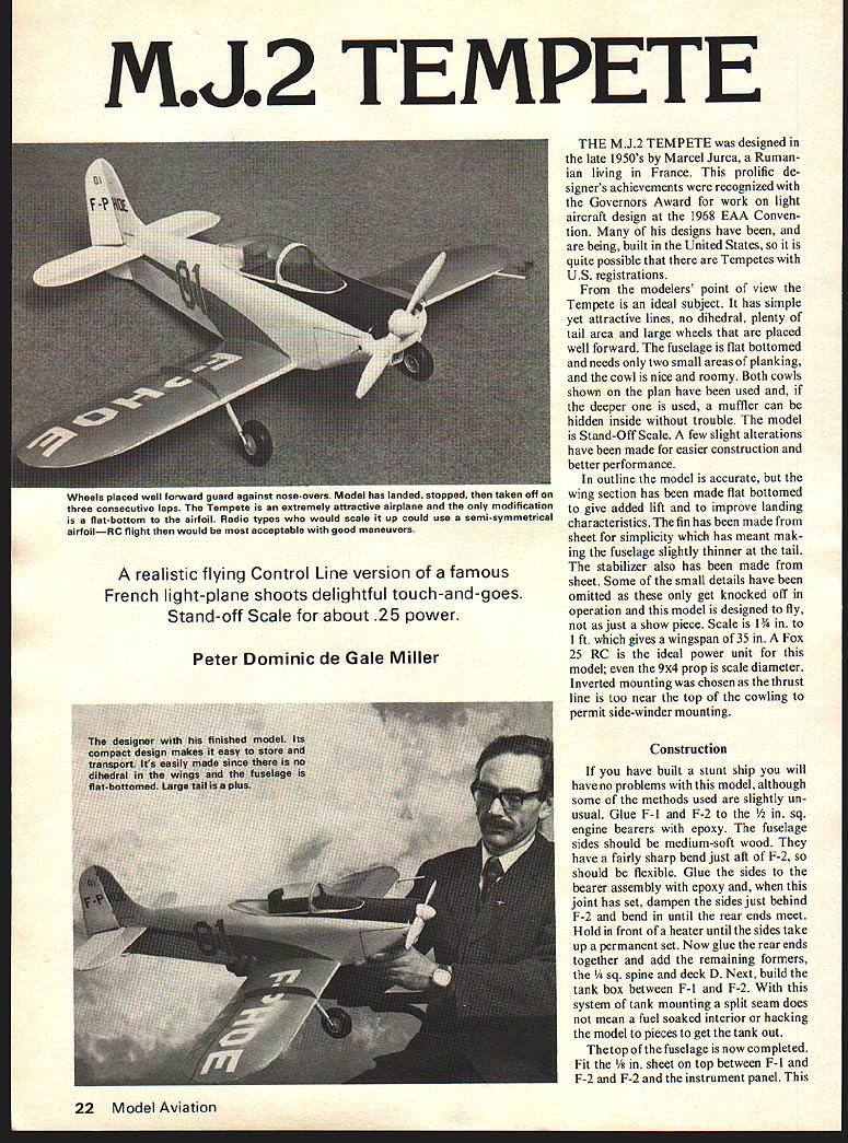
A realistic flying Control Line version of a famous French light-plane shoots delightful touch-and-goes. Stand-off Scale for about .25 power.
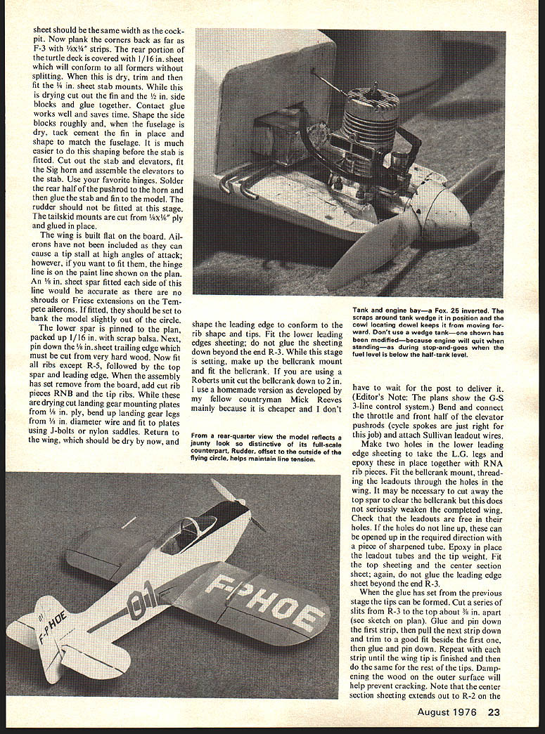
Peter Dominic de Gale Miller
THE M.J.2 TEMPETE was designed in the late 1950's by Marcel Jurca, a Rumanian living in France. This prolific designer's achievements were recognized with the Governors Award for work on light aircraft design at the 1968 EAA Convention. Many of his designs have been, and are being, built in the United States, so it is quite possible that there are Tempetes with U.S. registrations.
From the modelers' point of view the Tempete is an ideal subject. It has simple yet attractive lines, no dihedral, plenty of tail area and large wheels that are placed well forward. The fuselage is flat bottomed and needs only two small areas of planking, and the cowl is nice and roomy. Both cowls shown on the plan have been used and, if the deeper one is used, a muffler can be hidden inside without trouble. The model is Stand-Off Scale. A few slight alterations have been made for easier construction and better performance.
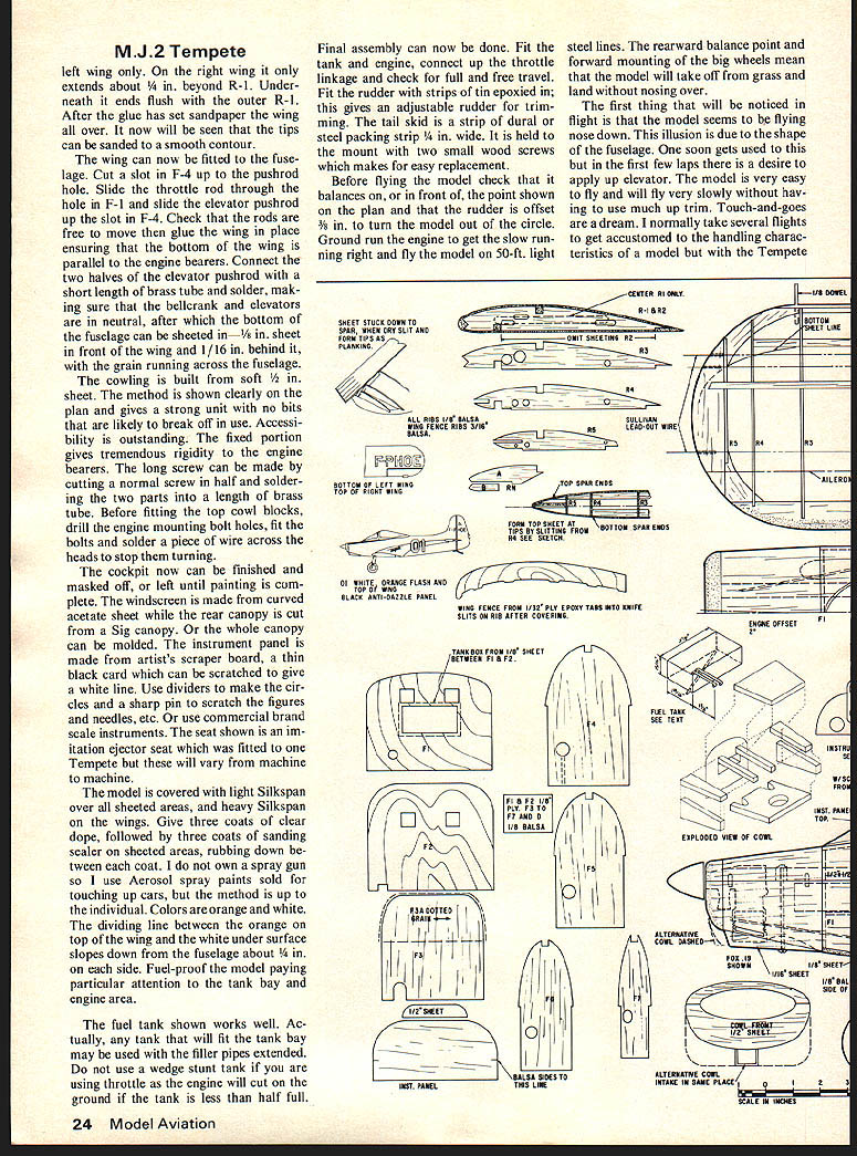
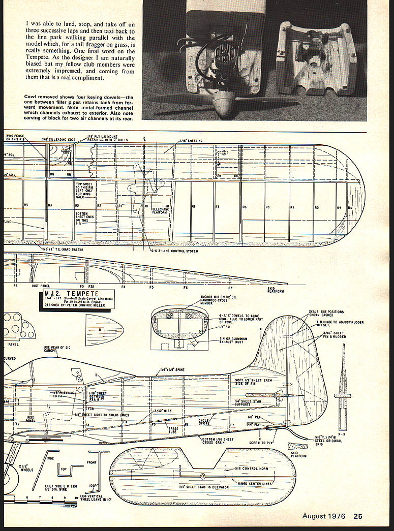
In outline the model is accurate, but the wing section has been made flat bottomed to give added lift and to improve landing characteristics. The fin has been made from sheet for simplicity which has meant making the fuselage slightly thinner at the tail. The stabilizer also has been made from sheet. Some of the small details have been omitted as these only get knocked off in operation and this model is designed to fly, not as just a show piece. Scale is 1 3/4 in. to 1 ft. which gives a wingspan of 35 in. A Fox 25 RC is the ideal power unit for this model; even the 9x4 prop is scale diameter. Inverted mounting was chosen as the thrust line is too near the top of the cowling to permit side-winder mounting.
Construction
If you have built a stunt ship you will have no problems with this model, although some of the methods used are slightly unusual. Glue F-1 and F-2 to the 1/2 in. sq. engine bearers with epoxy. The fuselage sides should be medium-soft wood. They have a fairly sharp bend just aft of F-2, so should be flexible. Glue the sides to the bearer assembly with epoxy and, when this joint has set, dampen the sides just behind F-2 and bend in until the rear ends meet. Hold in front of a heater until the sides take up a permanent set. Now glue the rear ends together and add the remaining formers, 1/4 sq. spine and deck D. Next, build the tank box between F-1 and F-2. With this system of tank mounting a split seam does not mean a fuel soaked interior or hacking the model to pieces to get the tank out.
The top of the fuselage is now completed. Fit the 1/8 in. sheet on top between F-1 and F-2 and F-2 and the instrument panel. This sheet should be the same width as the cockpit. Now plank the corners back as far as F-3 with 1/8 x 1/4 strips. The rear portion of the turtle deck is covered with 1/16 in. sheet which will conform to all formers without splitting. When this is dry, trim and then fit the 1/4 in. sheet stab mounts. While this is drying cut out the fin and the 1/2 in. side blocks and glue together. Contact glue works well and saves time. Shape the side blocks roughly and, when the fuselage is dry, tack cement the fin in place and shape to match the fuselage. It is much easier to do this shaping before the stab is fitted. Cut out the stab and elevators, fit the Sig horn and assemble the elevators to the stab. Use your favorite hinges. Solder the rear half of the pushrod to the horn and then glue the stab and fin to the model. The rudder should not be fitted at this stage. The tailskid mounts are cut from 1/8 x 1/16 ply and glued in place.
The wing is built flat on the board. Ailerons have not been included as they can cause a tip stall at high angles of attack; however, if you want to fit them, the hinge line is on the paint line shown on the plan. An 1/8 in. sheet spar fitted each side of this line would be accurate as there are no shrouds or Friese extensions on the Tempete ailerons. If fitted, they should be set to bank the model slightly out of the circle.
The lower spar is pinned to the plan, packed up 1/16 in. with scrap balsa. Next, pin down the 1/8 in. sheet trailing edge which must be cut from very hard wood. Now fit all ribs except R-5, followed by the top spar and leading edge. When the assembly has set remove from the board, add cut rib pieces R-1B and the tip ribs. While these are drying cut landing gear mounting plates from 1/8 in. ply, bend up landing gear legs from 1/8 in. diameter wire and rivet to plates using J-bolts or nylon saddles. Return to the wing, which should be dry by now, and shape the leading edge to conform to the rib shape and tips. Fit the lower leading edges sheeting; do not glue the sheeting down beyond the end R-3. While this stage is setting, make up the bellcrank mount and fit the bellcrank. If you are using a Roberts unit cut the bellcrank down to 2 in. I use a homemade version as developed by my fellow countryman Mick Reeves mainly because it is cheaper and I don't have to wait for the post to deliver it. (Editor's Note: The plans show the G-S 3-line control system.) Bend and connect the throttle and front half of the elevator pushrods (cycle spokes are just right for this job) and attach Sullivan leadout wires. Make two holes in the lower leading edge sheeting to take the L.G. legs and epoxy these in place together with R-1A rib pieces. Fit the bellcrank mount, threading the leadouts through the holes in the wing. It may be necessary to cut away the top spar to clear the bellcrank but this does not seriously weaken the completed wing. Check that the leadouts are free in their holes. If the holes do not line up, these can be opened up in the required direction with a piece of sharpened tube. Epoxy in place the leadout tubes and the tip weight. Fit the top sheeting and the center section sheet; again, do not glue the leading edge sheet beyond the end R-3.
When the glue has set from the previous stage the tips can be formed. Cut a series of slits from R-3 to the top about 3/8 in. apart (see sketch on plan). Glue and pin down the first strip, then pull the next strip down and trim to a good fit beside the first one, then glue and pin down. Repeat with each strip until the wing tip is finished and then do the same for the rest of the tips. Dampening the wood on the outer surface will help prevent cracking. Note that the center section sheeting extends out to R-2 on the
M.J.2 Tempete
left wing only. On the right wing it only extends about 1/4 in. along R-1. Underneath it ends flush with the outer R-1. After the glue has set, sandpaper the wing all over. It now will be seen that the tips can be sanded to a smooth contour.
The wing can now be fitted to the fuselage. Cut a slot in F-4 up to the pushrod hole. Slide the throttle rod through the hole in F-1 and slide the elevator pushrod up the slot in F-4. Check that the rods are free to move then glue the wing in place ensuring that the bottom of the wing is parallel to the engine bearers. Connect the two halves of the elevator pushrod with a short length of brass tube and solder, making sure that the bellcrank and elevators are in neutral, after which the bottom of the fuselage can be sheeted in 1/16 in. sheet in front of the wing and 1/16 in. behind it, with the grain running across the fuselage.
The cowling is built from soft 1/2 in. sheet. The method is shown clearly on the plan and gives a strong unit with no bits that are likely to break off in use. Accessibility is outstanding. The fixed portion gives tremendous rigidity to the engine bearers. The long screw can be made by cutting a normal screw in half and soldering the two parts into a length of brass tube. Before fitting the top cowl blocks, drill the engine mounting bolt holes, fit the bolts and solder a piece of wire across the heads to stop them turning.
The cockpit now can be finished and masked off, or left until painting is complete. The windscreen is made from curved acetate sheet while the rear canopy is cut from a Sig canopy. Or the whole canopy can be molded. The instrument panel is made from artist's scraper board, a thin black card which can be scratched to give a white line. Use dividers to make the circles and a sharp pin to scratch the figures and needles, etc. Or use commercial brass scale instruments. The seat shown is an imitation ejector seat which was fitted to one Tempete but these will vary from machine to machine.
The model is covered with light Silkspan over all sheeted areas, and heavy Silkspan on the wings. Give three coats of clear dope, followed by three coats of sanding sealer on sheeted areas, rubbing down between each coat. I do not own a spray gun so I use Aerosol spray paints sold for touching up cars, but the method is up to the individual. Colors are orange and white. The dividing line between the orange on top of the wing and the white under surface slopes down from the fuselage about 1/4 in. on each side. Fuel-proof the model paying particular attention to the tank bay and engine area.
The fuel tank shown works well. Actually, any tank that will fit the tank bay may be used with the filler pipes extended. Do not use a wedge stunt tank if you are using throttle as the engine will cut on the ground if the tank is less than half full.
Final assembly can now be done. Fit the tank and engine, connect up the throttle linkage and check for full and free travel. Fit the rudder with strips of tin epoxied in; this gives an adjustable rudder for trimming. The tail skid is a strip of dural or steel packing strip 3/4 in. wide. It is held to the mount with two small wood screws which makes for easy replacement.
Before flying the model check that it balances on, or in front of, the point shown on the plan and that the rudder is offset 3/8 in. to turn the model out of the circle. Ground run the engine to get the slow running right and fly the model on 50-ft. light steel lines. The rearward balance point and forward mounting of the big wheels mean that the model will take off from grass and land without nosing over.
The first thing that will be noticed in flight is that the model seems to be flying nose down. This illusion is due to the shape of the fuselage. One soon gets used to this but in the first few laps there is a desire to apply up elevator. The model is very easy to fly and will fly very slowly without having to use much up trim. Touch-and-goes are a dream. I normally take several flights to get accustomed to the handling characteristics of a model but with the Tempete I was able to land, stop, and take off on three successive laps and then taxi back to the line park walking parallel with the model which, for a tail dragger on grass, is really something. One final word on the Tempete. As the designer I am naturally biased, but my fellow club members were extremely impressed, and coming from them that is a real compliment.
Transcribed from original scans by AI. Minor OCR errors may remain.

