
Model Engines: And Their Essentials
FIRST THINGS FIRST. This is an article on engines, not on motors. I had a thermodynamics professor many years ago who was quite insistent that his students should understand that engines are not motors. Since I have always tried to learn my lessons well, my foremost pet peeve has remained when engines are called motors.
An engine is a prime mover. That is, an engine is a primary converter of energy to mechanical motion. Motors normally are secondary energy converters.
Actually, some model airplanes do use motors, but the power source is an electric motor, rubber strands, or CO2 motor. This article is about engines.
Introduction
Since their inception, model engines have been the two-cycle type. This means simply that the combustion process takes place every revolution. This is opposed to a four-cycle engine such as found in most automotive uses, where the combustion process in each cylinder takes place only every other revolution of the crankshaft.
The physical difference is that two-cycle engines have no valves or associated cams, pushrods, rocker arms, etc., that are present on four-cycle engines. Rather, two-cycle engines are ported through the crankcase and cylinder. They have fewer moving parts, reducing friction and allowing a much higher speed of operation.
Early model engines were of the spark-ignition type using a mixture of gasoline and oil for fuel and a spark system similar to the older automobiles — including breaker points, coil, condenser, and spark plug.
The glow plug was invented in the late 1940s (Ed.: Actually, much earlier, we hear.) and soon became the norm because of its simplicity and the increased power available in glow fuel.
While there is a growing interest in four-cycle model engines primarily due to their more pleasing and authentic sound and economical operation — to say nothing about their mechanical intrigue — so far they represent only a fraction of the total interest.
There is also a resurging interest in spark-ignition engines, not only in the adaptation of chainsaw engines to Giant scale models but in conversion of glow engines to ignition either for novelty or economic reasons. The modern ignition systems feature significant improvements, such as breakerless ignition and low battery drain.
Additionally, diesel model engines have been around with varying degrees of popularity for almost 40 years. There are diesel conversion kits for most modern glow engines available from Davis Diesel Development, along with a few diesel-designed engines produced primarily in Europe. Diesels are most popular where fuel volume or weight are prime considerations.
While many topics in this article are applicable to four-cycle, ignition, and diesel engines, the entire article is centered around the backbone of our hobby, the two-cycle glow engine.
The information presented here is intended to describe the critical components and outline various considerations in selecting and operating a model engine. The first step is to define certain terminology or "buzzwords" that you will encounter.
Part 1 — John Kilsdonk
Fundamentally, a two-cycle model engine works like this. The incoming fuel and air are mixed as they enter the venturi or carburetor. For front-intake engines, this mixture then is inducted through the port in the crankshaft and travels through the crankshaft into the crankcase. As the piston comes down, a positive pressure is generated in the crankcase, and the air-fuel mixture is forced up into the bypass port of the cylinder. By this time, the piston has gone through BDC (bottom dead center) and is now traveling up towards TDC (top dead center). As the piston in its upstroke traverses the bypass or cylinder intake port, it picks up the pressurized mixture and compresses it as it gets to top center. The mixture is then ignited slightly before TDC, and the pressure builds until the piston goes through TDC; after TDC the piston is pushed down by the combustion process until the exhaust port is uncovered, where the exhaust gases are evacuated. All this time another incoming charge is going through the same channels for the next stroke.
In actuality, this is a very fast process. Consider an engine running at 15,000 rpm; the complete intake, compression, combustion, and exhaust process takes place 250 times every second.
Buzzwords
Sometimes it seems like they were invented by experts just to confound others. Actually, they're shortened versions of longer terms that would be too cumbersome to use repeatedly in discussing a subject. This installment defines many of the terms associated with model engines (and more) for the in-depth discussions to follow.
Rings
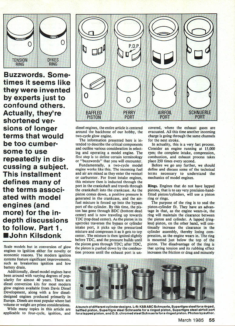
Engines that do not have lapped pistons, that is to say very precision-hand-fitted piston/cylinders, will use a piston ring for sealing. The purpose of the ring is to seal the piston-cylinder fit. They have an advantage in that, as the engine wears in, the ring will maintain the clearance between the piston and cylinder. A lapped (ringless) piston, on the other hand, will continually increase the clearance in the cylinder assembly, thereby losing compression, as the engine wears in. The ring is mounted just below the top of the piston. The disadvantage of the ring is that spring tension and its rubbing effect increases the friction or drag and minutely decreases performance.
Rings are usually made of a cast iron, normally Mehanite. There are two types of rings used in model engines. The first type is the tension ring. This is the more-common ring used today. It has a built-in tension, similar to a spring, that maintains the piston-cylinder seal irrespective of cylinder size or compression pressure. To some degree it also will compensate for small cylinder out-of-round conditions.
These rings can either be free-floating or pinned to prevent rotation. Engines using this system are ideal for general sport flying and feature extremely long life with very consistent operation.
The other type is the Dykes ring, which is a low-tension ring (more accurately, no tension). These are L-shaped rings and are fitted at the extreme top of the piston. They must be made very carefully and are not as tolerant to varying cylinder tolerances. The Dykes ring seal is principally obtained from the compression pressure which actually pushes the ring out against the cylinder only near TDC. The advantage of this design is lower friction for maximum performance. Generally though, their life span is somewhat shorter.
Baffled pistons
This is one of the oldest designs of pistons used on two-cycle engines. It is so named for the protrusion or baffle on the top of the piston. Engines with baffled pistons are sometimes referred to as "cross-flow" or "loop scavenged." The function of the baffle is to direct the incoming air/fuel mixture into the combustion chamber. Older engines had a less-defined baffle known as a dome on the top of the piston.
This is a very practical design for a first engine, and it is the design highly recommended for sport flying. Generally, engines using this configuration are conservatively timed and will operate comfortably in a wide range of peak rpms.
In recent years, some baffled-piston engines have included Perry Ports (PDP) which noticeably improve performance. Engines using a baffled piston are usually ported about 20% less than the Schnuerle-ported engines. This is because the cylinders and crankcases are less costly to produce.
Popular modern engines using this piston design are the O.S. non-Schnuerle engines (.15, .20, .30, .35, .40), HB engines, the Supertigre .60, Como .40 and .51, and the ever-popular K&B .40 (#4011).
Perry ports
Perry ports were developed by John Perry of carburetor fame. These are auxiliary ports, carefully located to both sides of the main bypass port on baffled-piston engines or next to the boost ports on Schnuerle engines. These ports use base crankcase compression to help purge or scavenge the residual exhaust gases. It is claimed that the proper use of this system can add about 500 rpm. Usually, engines using this system are labeled P.P. (Perry Port) or PDP (Perry Directional Port).
Airfoil ports
The airfoil-ported or laminar-ported engines are characterized by two angled bypass ports and a flat-top baffled piston. The airfoil bypass ports serve to direct the incoming air/fuel charge into the combustion chamber without the need of a baffle on the piston. This makes for a cleaner combustion chamber and, hence, more performance.
This system was patented by the Supertigre design, first used in 1960. To my knowledge it is still only used on some ST and Como engines. It is considered the forerunner of the Schnuerle-port application for model engines.
Engines using this port design have a conventional crankcase—usually the same as a baffled-piston engine. Thus, they are only slightly more expensive than the baffled-piston engines.
These engines are timed somewhat higher. Therefore, they run at higher rpms and have a narrower operating range. Perry Ports are sometimes also used with this design.
Between 1960 and 1975, the vast majority of Supertigre engines used this system. However, only a few modern engines still retain the airfoil port, including the ST-35, STG-60ABC, and the Como .40 ABC.
Schnuerle ports
This type of porting has continued to increase in popularity since the early 1970s. It was originally adopted for model engines in the early 1960s by Bill Wisniewski. Bill is the designer of most modern K&B engines. Originally, Bill used Schnuerle porting on his homemade CL speed engines (WART and TWA), and it eventually was seen in several production engines. Some of the first were the K&B 40S and K&B .15R, Rossi .15, HP .40, O.S. 40SR, and ST X-40.
This system is normally characterized by three bypass ports strategically designed and located. Normally, one bypass port is directly opposite the exhaust port, and two "boost" ports are located on each side of this port at roughly 90° angles from the center port. The bypass port resembles a small version of the ST laminar port with the boost ports being angled towards the bypass port. The principal advantage of the system, aside from the obvious increased porting area, is the combination of high-velocity mixture induction and the scavenging effect (purging) of the residual exhaust gases. Schnuerle porting incorporates a flat-top baffled piston literally identical to the "laminar" port piston. Actually the newer K&B engines use two bypass ports and two boost ports.
Because of the complicated casting requirements of the crankcase and more-involved machining process of the cylinder, engines with this porting system usually carry a premium price tag.
Most Schnuerle engines are timed for high performance and will operate much better at higher rpms. This means that, to realize the full advantage of this porting system, a small prop or higher nitro fuel may be required. Schnuerle engines produce significantly more power than baffled-piston designs and somewhat more power than laminar-port designs.
An ever-growing list of modern engines use Schnuerle ports. Some of the more popular ones are:
- All O.S. engines marked SR, SFR or VF (.10, .21, .25, .40, .45, .46, .50, .60, .90, 1.08)
- All Supertigre engines marked either X or S (.11, .21, .25, .29, .40, .45, .60, .75, .200, .250)
- K&B engines with metric nomenclature (3.5, 5.8, 6.5, 7.5)
- Other manufacturers may simply label them Schnuerle
Table No. 1: Measured Pressures
- Supertigre X-15 FR RC — ST S15-B Muffler F.T. — 18,000 rpm — 2.0 in H2O*
- O.S. .35 RC — O.S. No. 703 Muffler C.F. — 10,000 rpm — 6.0 in H2O
- O.S. .35 RC — Serno Muffler F.T. — 10,800 rpm — 6.0 in H2O
- O.S. H40 RC — O.S. No. 703 Muffler C.F. — 14,000 rpm — 7.0 in H2O
- O.S. H40 RC — MAC's Muffler F.T. — 14,600 rpm — 2.0 in H2O*
- O.S. .40 FSR — MAC's Muffler C.F. — 14,300 rpm — 2.0 in H2O*
- O.S. .40 FSR — O.S. No. 743 Muffler C.F. — 15,000 rpm — 8.0 in H2O
- O.S. .40 FSR — MAC's X Muffler F.T. — 16,000 rpm — 12.0 in H2O
- O.S. .40 FSR — OPS Tuned Muffler — 16,800 rpm — 8.5 in H2O
- K&B .40 (No. 8011) — MAC's X Muffler F.T. — 15,800 rpm — 1.0 in H2O
- HP .40 RR — Crankcase — 20,000 rpm — 16.0 in H2O
- Supertigre X-45 — ST X-45 Tuned Muffler — 16,000 rpm — 5.0 in H2O
- Supertigre G21/46 — ST S40B Muffler C.F. — 13,800 rpm — 7.5 in H2O
- Supertigre ST 600 F1 — ST 600B Muffler C.F. — 12,000 rpm — 7.5 in H2O
- ST 60 F1 — MAC's Muffler F.T. — 12,200 rpm — 1.0 in H2O
- O.S. .60 FSR — MAC's Muffler C.F. — 14,200 rpm — 2.0 in H2O
- O.S. .60 FSR — MAC's Muffler F.T. — 14,000 rpm — 2.0 in H2O
- Supertigre — Perry Pump/Regulator — 14,000 rpm — 1.0 to 8.0 in H2O (adjustable)
- Supertigre — ST X-60 Tuned Muffler — 14,700 rpm — 5.0 in H2O
F.T. = Flow-Through Muffler C.F. = Closed-Front Muffler * = Approximate Reading
Airfoil / Schnuerle notes
The airfoil-ported system was the forerunner of Schnuerle porting and influenced later developments. Perry Ports can be combined with either system to enhance scavenging and performance.
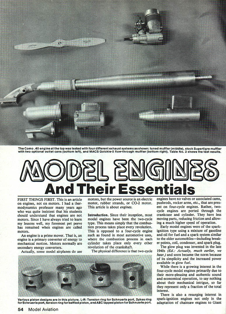
Table No. 2: Comparative Tests Of Various Exhaust Systems
Engine: Como .40 RC Fuel: 15% nitro Prop: 9 in. dia., 6-1/2 in. pitch
- No Muffler — 15.5 (×1000 rpm)
- Small Supertigre Muffler — 14.0 (×1000 rpm)
- Large Supertigre Muffler — 14.7 (×1000 rpm)
- MAC's Quickie-X Muffler — 15.4 (×1000 rpm)
- MAC's 6.5 Tuned Muffler — 15.8 (×1000 rpm)
ABC
Most older and some newer lapped-piston engines use a combination of steel and cast iron materials for the piston and cylinder. Ringed engines usually use a steel cylinder or sleeve with an aluminum piston and a cast iron ring. ABC-lapped engines means an aluminum piston (A) with a brass sleeve (B) that is chrome plated (C). Another version is AAC, which has the same aluminum piston but utilizes a chrome-plated aluminum cylinder.
These systems were developed by Supertigre in the late 1960s, and the ABC acronym is attributable to my old friend Harry Roe. At this writing, virtually every engine manufacturer provides some form of this system.
ABC pistons are machined from a high-silicon aluminum selected for both hardness and compatible thermal expansion characteristics with the base cylinder material. The chrome plating provides a reduced-friction wear surface that the aluminum piston is happy with.
The ABC system has been used with or without a piston ring, although the ring increases the friction (drag) and has lost popularity. These engines are characterized by a "squeaky" or bump feel at TDC when turned over cold without a glow plug. This is quite normal because as the operating temperature increases during running, the clearance will increase slightly and the fit becomes ideal.
These assemblies are usually found only in high-performance engines utilizing a flat-top piston and Schnuerle or airfoil porting. They always carry a premium price tag due to the materials and manufacturing processes involved. These engines are always labeled ABC.
TDC and BDC
TDC stands for top dead center, occurring when the piston is at the extreme top of its travel. Similarly, BDC refers to bottom dead center, and it occurs 180° away, when the piston is at the extreme bottom of its travel.
Dimensions for intake and exhaust timing are sometimes measured with respect to BDC or TDC. Usually, they are specified in degrees before top center (BTC or BTDC) or after top center (ATC or ATDC); similarly, they can refer to BDC such as ABDC, etc.
Timing
Dimensions of the various ports in two-cycle engines are usually specified in degrees of crankshaft rotation. These are critical dimensions, as they control the performance of the engine. The word timing refers to the opening or closing positions of the ports.
A typical modern Schnuerle-ported engine might have the following timing specification: exhaust 150°, bypass 125°, boost ports 130°, and crankshaft 190°.
Most modern model engines have the cylinder on the centerline of the crankshaft; therefore, cylinder timing points are symmetrical about BDC.
Our typical engine's timing, for example, is for the exhaust to open at 75° BBDC (or 105° ATC) and close at 75° ABDC (or 105° BTC) for a total opening of 150°. For the bypass and boost ports, simply divide the total duration by two, and it's that many degrees both before and after BDC.
It should be pointed out that this was not always true. Some older engines, in particular the original Fox 35s, had what was known as a desaxe configuration — where the cylinder was offset to one side to decrease the connecting rod angle, thereby increasing the mechanical advantage on the down (power) stroke.
Crankshaft timing is a different story, because the crank port is an inch or more away from the cylinder ports. In order for the fuel-air mixture to be available to the cylinder ports at the right time, and to maintain the proper pressure-vacuum relationships in the crankcase, the crank must anticipate the mixture requirements while controlling the proper crankcase pressures. Therefore, the crank timing of, say, 190° would translate into a typical opening at 45° ATC and a typical closing of 55° ABDC.
Engine timing is best left to the engine designers or hop-up artists, but it is another buzzword that is frequently flaunted and misunderstood.
Engines — Kilsdonk (continued)
Compression
Technically, compression is the reduction of volume of a given amount of a gas, such as air. This increases the pressure, resulting in a reaction force in the opposite direction. Compression, as generally referred to in model engines, usually is a subjective feel of the force required to turn the propeller over on a dry engine.
Compression is a direct function of piston-to-cylinder fit and attendant wear. Generally speaking, engines with more compression will perform better. There are some exceptions to this, particularly on ringed engines. A new ringed engine usually needs some running to wear in the ring for maximum compression. Similarly, a well-fitted ABC engine will give a false feeling of compression due to the cylinder taper and characteristic "bump" near TDC.
Compression should not be confused with compression ratio. The compression ratio should not be a concern for the average modeler; rather, it is best left to the engine designers and manufacturers. Just for the record, though, compression ratio is the total cylinder volume within the piston at BDC, including the volume in the combustion chamber not displaced by the piston, divided by the volume not displaced by the piston, or the remaining volume, with the piston at TDC. Compression ratio is more of a factor in four-cycle engines, and it is only of theoretical value in two-cycle engines, since the intake and exhaust ports are all wide open at BDC.
A more in-depth article on engines was authored by Glenn Lee and published in Model Aviation in 1979.
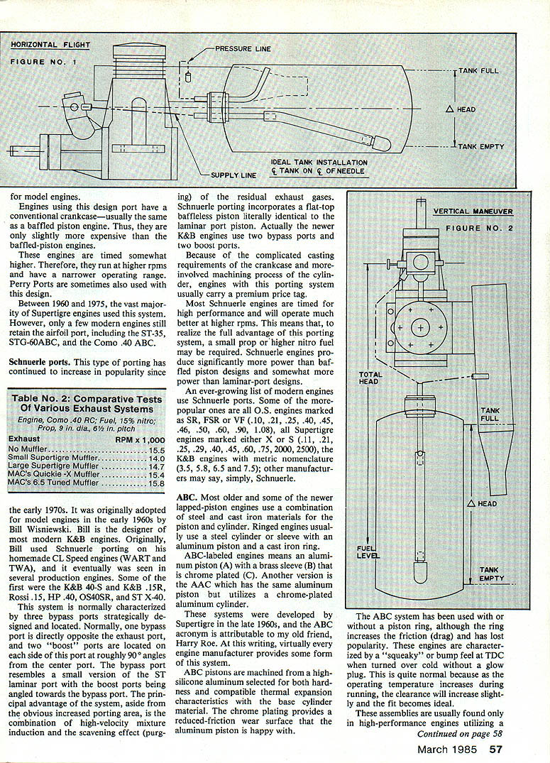
Fuel system pressurization
Pressurization of the fuel system, in particular the need for it, is often misunderstood. One should consider that without some form of pressurization, the engine is left to draw or suck its fuel from the tank by means of an (infinitesimally) small amount of suction or negative pressure at the engine's venturi. Obviously, the size of the venturi or carburetor opening controls how much suction is available. Even with the tiniest venturi, only a few inches of vertical suction is possible. Worse, by reducing the venturi/carburetor diameter, we also restrict the engine's ability to breathe incoming air, resulting in diminished power.
In an effort to maximize the engine's power, the largest practical venturi size is preferred. This necessitates some form of fuel system pressurization. Pressure improves the delivery of fuel to the engine, resulting in a more consistent needle valve setting from the beginning to the end of the tank.
The preferred fuel tank location is always with the centerline of the fuel tank directly on the centerline of the needle valve. This provides consistent fuel head pressure in all flight attitudes. Sometimes this is not easily done. Slight variations (tank offset, etc.) will work satisfactorily if some form of pressure is used. Personally, I try to side-mount my engines during model construction. This generally makes it easier to keep these centerlines together.
With any fuel tank, there will be a fuel head change from full tank to empty. Generally, this represents about two inches of pressure head variation. If we assume an engine can draw two inches of fuel vertically, the actual head variation on our two-inch-high tank without pressure changes is from 8 inches at full to 1 inch at empty — a 66% variation.
Add a good muffler pressure system with five inches of pressure, and go through the numbers again: 8 inches at full and 6 inches at empty — only a 25% variation. That's quite an improvement. This will translate into a much more consistent engine run even if you are a novice just flying around level.
Vertical maneuvers and high G-load turns are also enhanced by pressure. Consider an RC model in a prolonged vertical climb with less than a half tank of fuel. Without some form of pressurization, the engine must draw eight inches or more of fuel on its own. Without pressure it can't be done, so the mixture goes lean with a resultant power loss. Therefore, some form of fuel pressurization is always recommended.
Crankcase pressure uses the average pressure available in the engine's crankcase. Actually, as the engine's piston goes up and down, crankcase pressure varies from plus to minus. However, due to the timing of the induction port, there is more positive pressure in each cycle than there is negative pressure (vacuum), resulting in an average positive pressure. This average pressure is approximately 0.5 PSI — about 14 inches of water.
Crankcase pressure does not work as well with carbureted engines as it does with muffler and pulse-rotor systems. It is ideal, though, for full-throttle-only applications such as for some CL and FF events and RC pylon racing, requiring maximum engine performance.
Muffler or tuned-pipe pressure utilizes the back pressure present in the exhaust system to pressurize the fuel tank. This system modulates well with part-throttle operation, so it works very well with carbureted engines. Typical muffler pressures range from one to eight inches of water, dependent on exhaust or muffler configuration. Refer to Table No. 1.
There are also some external pumps manufactured by Perry and Robart that provide even greater pressure boost. These pumps have an internal regulator to provide consistent pressure and are driven either by crankcase pressure or engine vibration.
Any fuel system pressurization system is, of course, additive to the pre-existing venturi suction. Some form of pressure is most certainly recommended for almost every model engine use. It is free, so why not use it.
I authored a more in-depth article devoted entirely to muffler pressure in the June 1979 Model Aviation. This article is worth reading if you would like more detail.
Mufflers and noise
Mufflers are required at most RC flying fields. Personally, I feel this can be only a plus for the hobby. Many flying fields have been lost as a result of noise problems. Most modern engines are now shipped with a muffler, or at the very least a muffler is available from the manufacturer as a separate item. Additionally, there are some excellent aftermarket mufflers available in various configurations for both conventional and special applications, such as helicopters, scale, and racing.
One should realize that each muffler design has its own characteristics of noise reduction, exhaust back pressure, and resultant performance.
Most model engine mufflers consist of an adapter that bolts directly to or is strapped to the engine's crankcase and fits tightly over the exhaust stack. This adapter transfers exhaust gases into an expansion chamber or large tube. At the end of the expansion chamber, there is an outlet tube which restricts the flow, thereby generating the back pressure that we can use to pressurize the fuel tank.
Generally, back (muffler) pressure and noise reduction of a given engine are inversely proportional to performance. In other words, the smaller the outlet, the more restriction, the less noise, and the less performance.
Some mufflers, particularly aftermarket models, are available in a "flow-through" version. Unlike conventional configurations these mufflers have an opening in the front with a straight-through tube covered with another concentric tube that forms the outside of the expansion chamber.
Flow-through mufflers generally provide maximum performance with a much lessened noise control. Primarily, these are used for maximum performance events where some muffler is required, such as Club 500 pylon racing.
Next month we will cover tuned pipes, engine break-in, idle settings, and many other topics. Please stay tuned.
Transcribed from original scans by AI. Minor OCR errors may remain.

