
Model Engines: And Their Essentials
Glow plugs
Construction
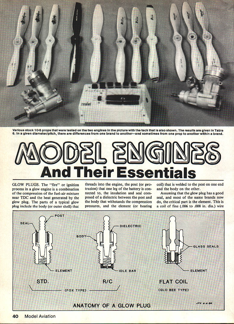
- The ignition process in a glow engine is a combination of compression of the fuel–air mixture near TDC (top dead center) and heat generated by the glow plug.
- A typical glow plug consists of:
- body (outer shell) that threads into the engine,
- post (protrusion) to which one leg of the battery is connected,
- insulation and seal (dielectric) between post and body that withstands compression pressures,
- element (heating coil) welded to the post on one end and the body on the other.
- The critical part is the element: a coil of fine (.006 to .008 in. dia.) platinum-alloy wire that glows when sufficient voltage is applied.
Types and heat range
- Coils: flat coils (high performance) or long spiral (spring-like) coils.
- Heat range depends on wire size and alloy. Start with the dealer's recommendation and experiment if needed.
- Flat-coil plugs (e.g., GloBee) often give up to ~500 rpm increase in performance but cost more due to special glass seals.
- "RC" or "Idle Bar" plugs have a small strap partially covering the coil to shield it from raw fuel at low idle and during transitions. They improve idle reliability but can cost up to ~500 rpm at full throttle in some sport applications.
Reach
- Reach = thread depth into the engine. Some small engines use short reach; most modern engines use long reach.
- Reach is specified by the engine manufacturer.
- In some designs (e.g., certain Cox engines) the glow plug is integral with the cylinder head; the entire head must be replaced to change the plug.
- Workaround: a long plug plus two extra standard copper glow-plug washers (three total washers) can approximate a short-reach plug in a pinch.
Starting batteries and electrical requirements
- After the engine starts, each combustion reheats the plug element and sustains ignition; the starting battery can usually be removed with no effect on a running engine.
- A standard model-engine glow plug requires a DC voltage of at least 1.0 V at the plug. Normally a 1.5–2.0 V DC source is used; excess voltage is dropped in lead wires or a rheostat.
- Typical glow-plug current draw: about 1.5 to 4.0 amps, depending on coil wire and actual voltage at the plug.
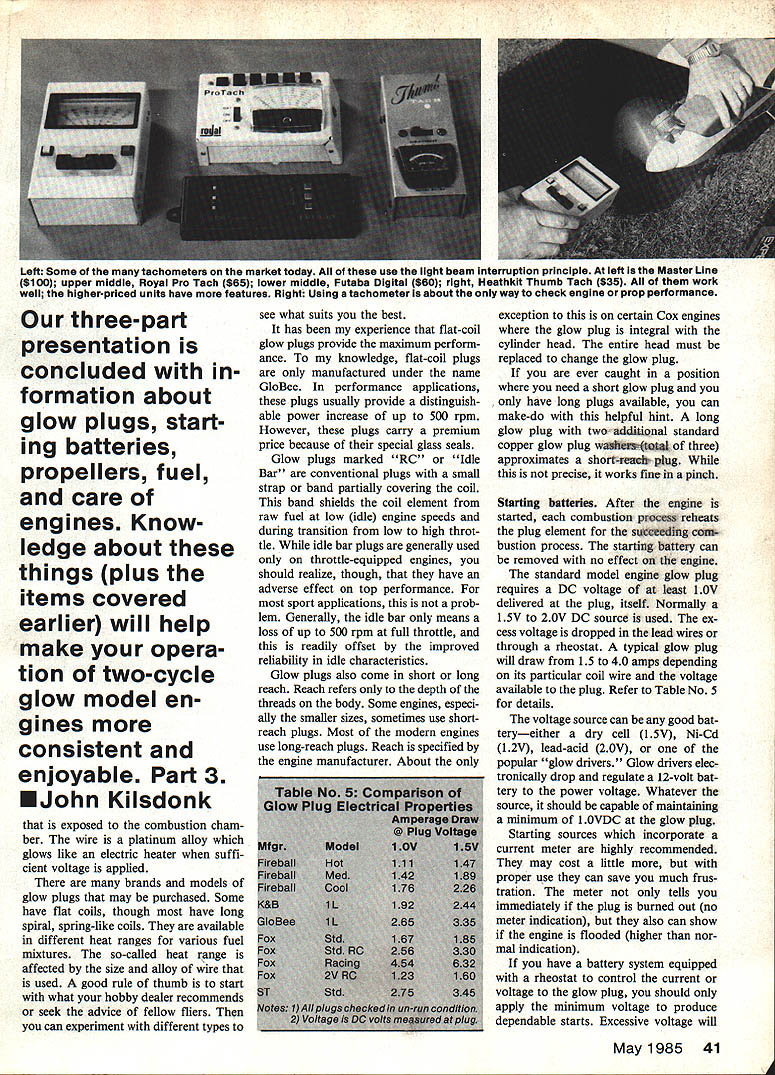
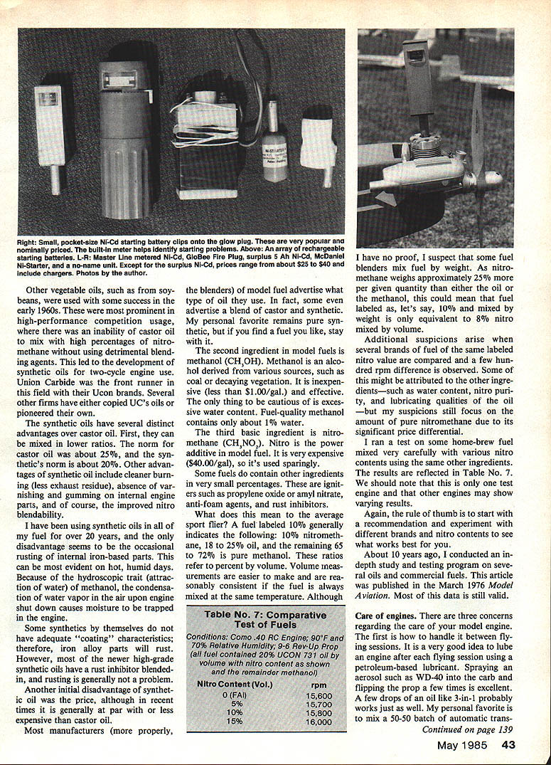
- The voltage source can be any good battery (dry cell 1.5 V, Ni-Cd 1.2 V per cell packs as appropriate, lead-acid, or an electronic "glow driver" that drops and regulates 12 V down to the proper voltage). Whatever the source, it should maintain a minimum of 1.0 V DC at the plug.
- Starting sources that incorporate a current meter are highly recommended: they indicate a burned-out plug (no current) or a flooded engine (higher-than-normal current).
Table No. 5: Comparison of Glow Plug Electrical Properties — Amperage Draw @ Plug Voltage
- Note: voltage is DC measured at plug; plugs checked in un-run condition.
Mfg'r. / Model .......... 1.0V ...... 1.5V
- Fireball Hot (Mot.) ... 1.11 ...... 1.47
- Fireball Med. ......... 1.42 ...... 1.89
- K&B Cool ............. 1.76 ...... 2.26
- K&B 1L ............... 1.92 ...... 2.44
- GloBee ............... 2.65 ...... 3.35
- Fox Std. RC .......... 1.67 ...... 1.85
- Fox Std. RC (alt) .... 2.56 ...... 3.30
- Fox Racing ........... 4.54 ...... 6.32
- Fox 2V RC ............ 1.23 ...... 1.60
- Cox .................. 2.75 ...... 3.45
Notes:
- All plugs checked in un-run condition.
- Voltage is DC volts measured at plug.
Setting voltage and practical tips
- Excessive voltage will electrically strain or even burn out the plug element and significantly reduce plug life.
- Rule of thumb: with the same lead wires and connectors you normally use, take a new plug, slowly increase voltage until you see a faint glow in average indoor light (not bright sunlight). Note the control position or meter reading and use that same setting at the flying field.
- If you don't have a current/voltage control, increasing the length of the lead wires will drop voltage.
Propeller nomenclature
- Example: a 10-6 propeller — the first number (10) is the diameter in inches; the second number (6) is the pitch, related to blade angle.
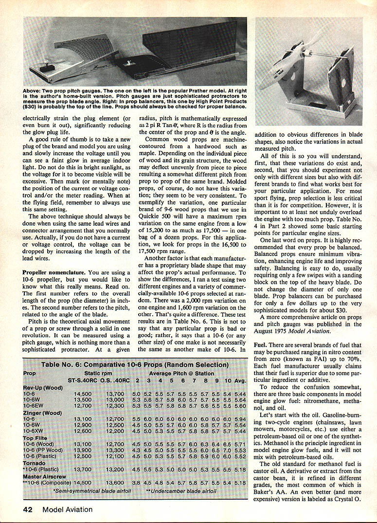
- Pitch = theoretical axial movement of a prop through a solid in one revolution. At a given radius, pitch = 2πR · tan(θ), where R is radius and θ is blade angle.
- Wood props are machine-contoured from hardwood (e.g., maple), and individual pieces can vary in pitch due to wood grain; molded props are more consistent.
- Different manufacturers use proprietary blade shapes; two 10-6 props from different makers can show large rpm differences (tests showed variations of up to 2,000 rpm on the same engine).
- Experiment with different sizes and brands to find what works best; for sport flying prop selection is less critical than in competition, but avoid overloading the engine.
- Always balance props to minimize vibration and improve engine life and safety. Balancing is easy (sanding on the heavy blade) and prop balancers are inexpensive.
Table No. 6: Comparative 10-6 Props (Random Selection)
- Columns: Prop — Static rpm (ST-S.40RC) — Static rpm (C.S.40RC) — Average Pitch (in.)
Rev-Up (Wood)
- 10-6 .............. 14,500 / 13,700 — Avg Pitch 5.44
- 10-6W ............. 13,500 / 13,700 — Avg Pitch 5.44
- 10-6EW ............ 12,700 / 12,300 — Avg Pitch 5.60
Zinger (Wood)
- 10-6 .............. 13,100 / 12,700 — Avg Pitch 6.00
- 10-6W ............. 12,900 / 12,200 — Avg Pitch 5.44
- 10-6XW ............ 12,600 / 12,200 — Avg Pitch 5.45
Top Flite
- 10-6 (Wood) ....... 13,100 / 12,700 — Avg Pitch 5.55
- 10-6 (PP Wood) .... 13,900 / 13,300 — Avg Pitch 5.44
- 10-6 (Plastic) .... 12,500 / 12,400 — Avg Pitch 5.52
Tornado
- 10-6 (Plastic) .... 13,700 / 13,200 — Avg Pitch 5.18
Master Airscrew
- 10-6 (Composite) . 14,500 / 13,600 — Avg Pitch 5.18
Notes: different blade airfoils (semi-symmetrical or undercambered) affect performance.
(See the published comparative tests for full station-by-station pitch measurements.)
Fuel
- Model glow fuel has three basic components: nitromethane, methanol, and oil. Some fuels include small amounts of ignition aids (e.g., propylene oxide, amyl nitrate), anti-foam agents, or rust inhibitors.
- Typical labeled nitro content ranges from 0% (FAI) up to ~70%. Manufacturer claims vary, and other small differences (water content, nitro purity, oil type) affect performance.
Oil
- Methanol (principal solvent/fuel) will not mix with petroleum-based oils; model fuels use castor oil, synthetic oils, or blends.
- Castor oil (e.g., Baker's AA, Crystal O) is vegetable-derived and was the old standard.
- Synthetic oils (e.g., Ucon series) became popular for better nitro blendability, cleaner burning, less varnishing/gumming, and lower oil ratios (typical castor ~25% by volume vs. synthetic ~20%).
- Drawback: some synthetics alone can allow rusting of iron-based parts because methanol is hygroscopic and traps moisture after shutdown. Many modern synthetics include rust inhibitors.
- Recommendation: choose a fuel you trust and stick with it. Many commercial fuels state oil type or a castor/synthetic blend.
Methanol
- CH3OH. Principal ingredient and solvent. Fuel-grade methanol typically contains about 1% water; excessive water reduces performance.
Nitromethane
- CH3NO2. The power additive; expensive and used sparingly. Labeled nitro percentages are by volume (e.g., "10%" means ~10% nitromethane by volume). If a blender mixed by weight (rather than volume), the nitro percentage labeled by volume could differ slightly because nitromethane is denser.
- Example composition for a labeled 10% fuel: ~10% nitromethane, ~18–25% oil, remainder methanol (percentages by volume).
Performance and testing
- Small differences in rpm observed between brands with the same labeled nitro can come from oil type, water content, nitro purity, or actual nitro quantity.
- Test results (one engine example) with 20% Ucon 731 oil by volume and remainder methanol:
Table No. 7: Comparative Test of Fuels (Como .40 R/C Engine; 90°F; 70% RH; Rev-Up 9-6 prop)
- Nitro Content (vol.) — rpm
- 0% (FAI) — 15,600
- 5% — 15,700
- 10% — 15,800
- 15% — 16,000
- Rule of thumb: start with a recommended brand and experiment with nitro contents/brands for your engine and flying style.
Care of engines
There are three primary concerns: between flying sessions, prolonged storage, and after a crash.
Between sessions (post-flight lubrication)
- Lubricate after each flying session with a petroleum-based lubricant:
- Spray a small amount of WD-40 into the carb and flip the prop a few times, or
- A few drops of a general-purpose oil (e.g., 3-in-1).
- A popular method: a 50/50 mix of automatic transmission fluid (ATF) and a light petro-based igniter (lighter fluid). Procedure:
- Disconnect the fuel line, close the throttle to idle, connect the starting battery.
- Put several drops of the ATF/lighter-fluid mix in the carb and short the starter to turn the engine, repeating 3–4 times.
- This burns residual methanol and coats internal parts with lubricating ATF. It can run the engine briefly for better coverage (somewhat messy).
- For engines with a carb: close the barrel after flying and keep it closed during storage. For engines without a carb: stuff a paper towel in the venturi. Stuff a paper towel in the muffler or exhaust openings as well.
Prolonged storage (months/winter)
- Use any of the above lubrication procedures, with a heavier application of oil for extended storage.
- Store the engine in an airtight plastic bag for long-term storage (six months or longer).
After a crash
- Do not rotate the crankshaft. Do not turn over the engine once it's removed.
- Carefully remove the engine from the model. Remove the prop remnants and then carefully remove only:
- the carburetor,
- the cylinder head,
- the backplate.
- Do not disassemble piston, cylinder, crank, or bearings unless there is obvious damage.
- Clean procedure:
- Fill a small container with hot tap water and add a generous amount of liquid detergent.
- Soak the engine and removed parts in the detergent solution for ~10 minutes. Again, do not rotate the crankshaft while soaking.
- Remove and flush under hot tap water. Repeat soak/flush if grit or dirt remains.
- Use a toothbrush or pipe cleaner if necessary.
- Inspect for obvious damage (bent crankshaft, damaged prop drive washer, cracked case). Minor bent or chipped rod-end features may not be critical.
- If everything looks OK, slowly rotate the crankshaft and check for binding or sticking.
- Reinstall the carburetor, cylinder head, and backplate carefully.
- Reconnect fuel and starting system, and test-run. If internal damage is suspected, disassemble further only with care and preferably under the guidance of an engine specialist.
- Avoid unnecessary disassembly; unnecessary work after a crash causes additional damage.
Conclusion
- This article covered glow plugs, starting power, propeller nomenclature and selection, fuels, and engine care essentials. Each topic can be expanded in greater depth.
- Experienced hobbyists often take routine knowledge for granted. Consider helping newcomers by giving lessons, conducting clinics, holding tech talks, supporting AMA activities, or sharing knowledge through articles and mentorship.
Transcribed from original scans by AI. Minor OCR errors may remain.

