
Model Engines: And Their Essentials - Part 2
Tuned Pipes
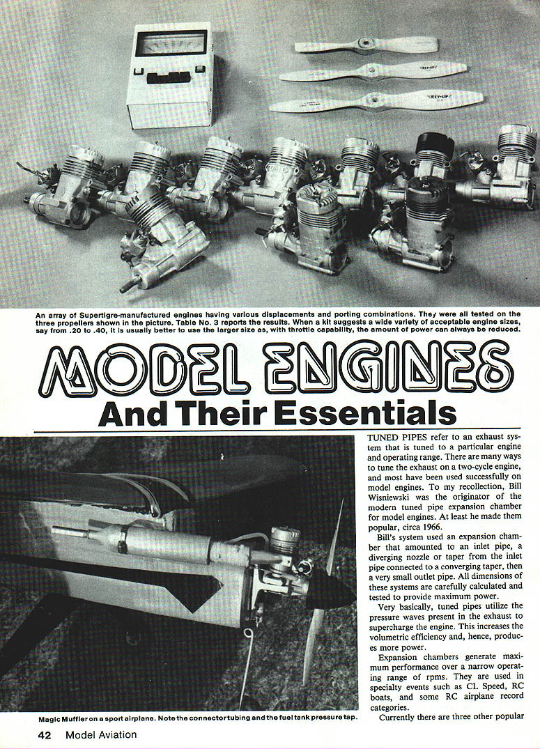
The term "tuned pipes" refers to exhaust systems tuned to a particular engine and operating range. Tuned pipes utilize pressure waves in the exhaust to improve scavenging and effectively supercharge the engine, increasing volumetric efficiency and power. Expansion‑chamber systems deliver maximum performance over a relatively narrow RPM band and are used in specialty events (CL Speed, RC boats, some RC airplane records).
History and common types:
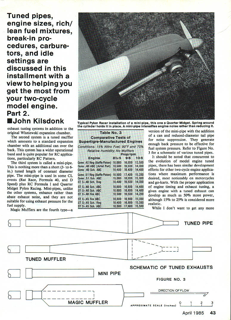
- Expansion chamber (Wisniewski style): inlet pipe → diverging nozzle → converging taper → small outlet pipe. Dimensions are carefully calculated and tested for peak power.
- Tuned muffler: an expansion chamber with an additional can/over‑back section; wider operational band, popular for RC Pattern.
- Mini‑pipe: a short (3–6 in.) tuned length of constant diameter pipe; used in some CL events (Rat Race, Formula 40, D‑Speed) and in RC Formula, Quarter Midget, and Pylon Racing. Mini‑pipes tend to increase exhaust noise and can be used to aid fuel feed by exhaust pressure.
- Magic Muffler: a mini‑pipe with an added can and reduced‑diameter tailpipe to suppress noise while still generating enough back pressure for fuel‑system pressure.
Notes:
- Pylon racers commonly mount a mini‑pipe with a spring around the cylinder.
- Model engine tuned‑pipe development paralleled similar work on motorcycles and go‑karts.
- Claims vary, but realistically a tuned exhaust may yield 15%–25% more power (50% is sometimes quoted but optimistic).
Tuning Procedure (pipe tuning and testing)
Effective exhaust timing depends on engine exhaust‑port timing, air density, exhaust temperature, and RPM, so you generally cannot bolt on a tuned pipe and expect peak performance without tuning.
Basic rule:
- Tune the pipe to static (ground) RPM. In flight the engine typically runs 500–1,500 RPM higher than on the ground (racing models may be several thousand RPM higher).
- To approximate flying RPM on the ground, fit a smaller prop (example: fly with a 9‑6 or 10‑5 instead of a 10‑6; or 11‑6 instead of 11‑7).
- Run the engine at maximum RPM with the smaller prop and record the RPM.
- Shorten or lengthen the exhaust about 1/2 in., re‑measure RPM.
- If engine speed increases, you are moving in the correct direction.
- If it decreases, reverse direction.
- If no change, you are probably close to the optimal length.
- When you see increases, continue in ~1/4‑in. increments until no further improvement.
- Install the flying prop and check actual in‑flight performance.
Helpful hints:
- Always readjust the needle valve after changing pipe length. Proper length changes usually require a richer needle setting because volumetric efficiency increases.
- Cut material as necessary from the header pipe (attached to engine) — not from the expansion chamber — when shortening a system.
- Remember exhaust tuning depends on air density: dramatic temperature, altitude, or large nitro content changes will require pipe length changes.
- Tune the system on the ground first, then verify and fine‑tune in flight.
Refer to Figure No. 3 (if available) for schematics of various tuned‑pipe types.
Engine Size and Displacement
"Engine size" refers to piston displacement, usually given in cubic inches: .15, .25, .40, .60, etc. Some engines use cubic centimeters (cc); 1 cc ≈ 0.061 cu. in.
To calculate displacement:
- Measure bore (B) and stroke (S).
- Formula: Displacement = π × (B/2)^2 × S.
Example:
- Measured bore B = 0.866 in.
- Measured distance top cylinder to top piston at BDC = 0.942 in.
- Measured distance at TDC = 0.163 in.
- Stroke S = 0.942 − 0.163 = 0.779 in.
- Displacement = 3.14 × (0.866/2)^2 × 0.779 ≈ 0.459 cu. in. (≈ .46)
Table No. 3 (referenced) shows relative performance of engines of various displacements and porting types.
Choosing Engine Size
Correct engine sizing is often a dilemma. Consider:
- Fit in the model and mounting space.
- Price and availability.
- Manufacturer kit recommendations are often wide; if a kit lists .20–.40, a .20 will usually be underpowered.
- If in doubt, choose the largest recommended size — you have a throttle to control speed and extra power helps in wind, short fields, or heavy takeoffs.
Rich and Lean (mixture settings)
Definitions:
- Rich: excess fuel relative to available air.
- Lean: excess air relative to available fuel.
- Stoichiometric: the theoretical ideal fuel/air ratio where combustion is chemically balanced (not necessarily best for performance or engine life).
Needle valve operation:
- Turn the needle out (CCW) to richen (allow more fuel).
- Turn the needle in (CW) to lean (restrict fuel).
Audible cues and "four‑cycle"/"two‑cycle" terminology:
- A rich setting produces a slow, gurgling, low‑frequency sound called a "four‑cycle" sound (engines actually still fire every revolution but sound similar to a four‑stroke).
- As you lean, RPM and frequency increase until a crossover where the sound sharpens to the "two‑cycle" tone; this can be a large RPM change for a small needle movement.
- Continue leaning until you reach a flat (stoichiometric) region for a short span, then further leaning will cause RPMs to fall and the engine will be over‑lean.
- Over‑leaning will quickly damage an engine; if unsure, err on the rich side.
Quick cross‑check — "Charmin" test:
- When you think the needle is correct, briefly squeeze the fuel line.
- If engine speed increases audibly, the mixture is acceptably rich. If not, open (richen) the needle until you hear an increase.
Propeller Sizing — Table No. 4 (Two‑Cycle Engine Recommended Propeller‑Sizing Chart)
Nominal engine size — Recommended flying prop(s) — Test prop
- .10 — 7‑2, 7‑3 — 6‑3
- .15 — 7‑4, 7‑6 — 6‑4
- .20 — 8‑4 — 7‑4
- .25 — 8‑6, 9‑5 — 7‑4
- .30 — 9‑5, 9‑6 — 8‑4
- .35 — 9‑6, 10‑5 — 8‑4
- .40 — 9‑6, 10‑6 — 8‑6
- .45 — 9‑6, 11‑6 — 8‑8
- .51 — 10‑6, 11‑5 — 9‑6
- .60 — 11‑6, 11‑7, 12‑5 — 10‑6
- .75 — 12‑6, 13‑5 — 11‑6
- .90 — 14‑6 — 12‑6
- Test prop note: Cut from a prop about 1 in. larger in diameter (preserve and balance the hub). Use a rigid, weighted test stand for running non‑throttle engines or racing engines.
Break‑in Procedures
General modern approach:
- Modern machining and bearing practices reduce required break‑in. Minimal break‑in is usually sufficient.
- For carburetor‑equipped engines, break in in the airplane using a slightly smaller prop than eventual use.
In‑airplane break‑in (recommended):
- Fit a propeller one size smaller than final (e.g., 9‑6 instead of 10‑6).
- Open the needle 5–6 turns and start at about half throttle.
- Run 3–4 minutes at this setting, then gradually open to full throttle.
- Slowly lean the needle to the four‑cycle to two‑cycle transition, then back off ~1/4 turn.
- Adjust idle to an acceptable value (it will improve after a few flights).
- Refill fuel and fly: take off at full throttle, reduce to half/three‑quarters for a minute to cool, then full for a minute; repeat for the flight.
- Repeat flights, gradually leaning until full power is achieved. After a few full‑bore flights, fine‑tune idle.
Test‑stand break‑in (non‑throttle or racing engines):
- Mount engine rigidly on a weighted test stand with a test prop.
- Fill the tank for ~5 minutes running.
- Open needle 5–6 turns and start; run very rich at high speed for ~1 minute.
- Gradually lean over ~5 minutes toward two‑cycle operation, then shut down and refill.
- Subsequent runs: cycle between two‑cycle and four‑cycle settings in 30‑second increments until engine holds two‑cycle for two minutes without sagging.
- Set slightly rich for the first few flights to ensure complete break‑in.
A practical rule: three flights cycling part‑to‑full throttle and two more at full throttle (about an hour total flying) is a good break‑in guideline.
Idle Settings and Carburetor Types
Glow plugs:
- Use a good or new glow plug recommended for the engine.
- Two common failure modes: broken coil wire (open circuit) or over‑oxidized coil (still conductive but poor heat transfer and performance). If engine speed drops noticeably when you remove the starter battery, the plug is worn.
Main carburetor types and idle controls:
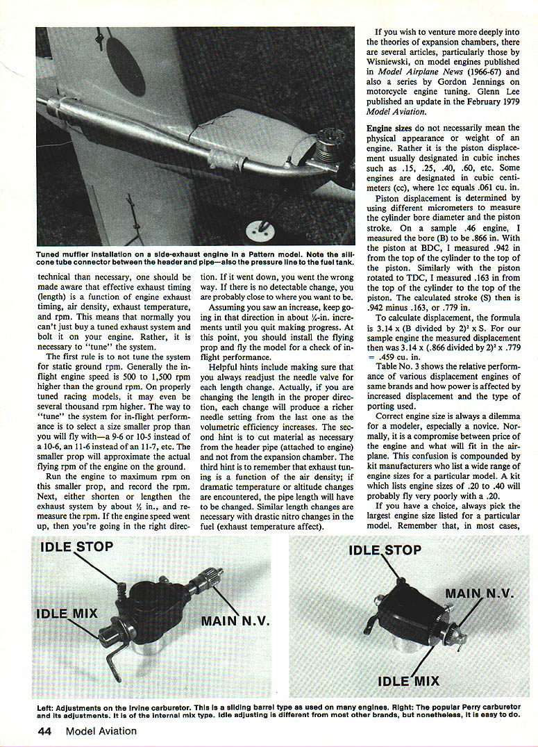
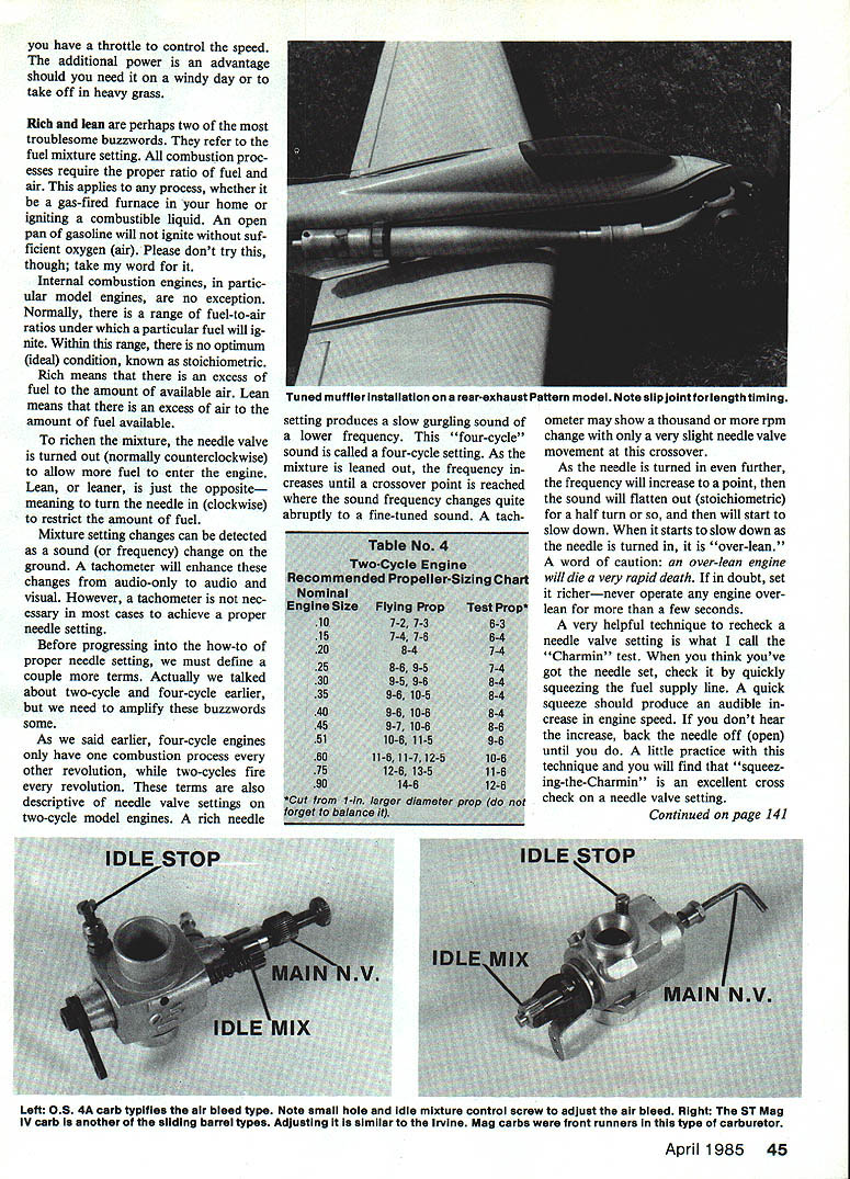
- Air‑bleed carburetor:
- High‑speed (main) needle plus a small air‑bleed screw near a drilled hole.
- Turning the screw in (CW) restricts bleed and richens idle; out (CCW) leans idle.
- Internal‑mix carburetor (e.g., Perry):
- Idle mixture is adjusted by a large wheel on the main needle side with a slot and (+)/(−) markings. Rotate toward (+) (CW) to richen, toward (−) (CCW) to lean.
- Sliding‑barrel carburetor:
- Barrel rotates and moves axially. Idle mixture is controlled by a second needle opposite the main needle; CW leans, CCW richens with high sensitivity.
Idle stop:
- An idle stop screw sets the fully‑closed barrel position. The author prefers to use radio throttle trim to control closed position and kills the engine by pulling trim to full.
Setting the Mixture (practical steps)
- Fit a known good glow plug.
- Open the carb to wide‑open throttle (WOT). Adjust the high‑speed (main) needle to maximum performance.
- Close the throttle as far as possible and note if the engine dies.
- If it dies, determine whether it dies rich or lean:
- Gurgles/burps before dying → too rich.
- Dies slowly without burbling → too lean.
- Restart, set to a slightly higher stable RPM, and slowly close the throttle while listening.
- Adjust the idle mixture screw gradually (per your carb type) until idle quality improves and the engine runs longer at lower idle speeds before dying.
- Final idle adjustments are best after a few flights when the engine has cooled and mating surfaces have seated.
Part 2 — John Kilsdonk
Transcribed from original scans by AI. Minor OCR errors may remain.

