
The Model: Fly Baby
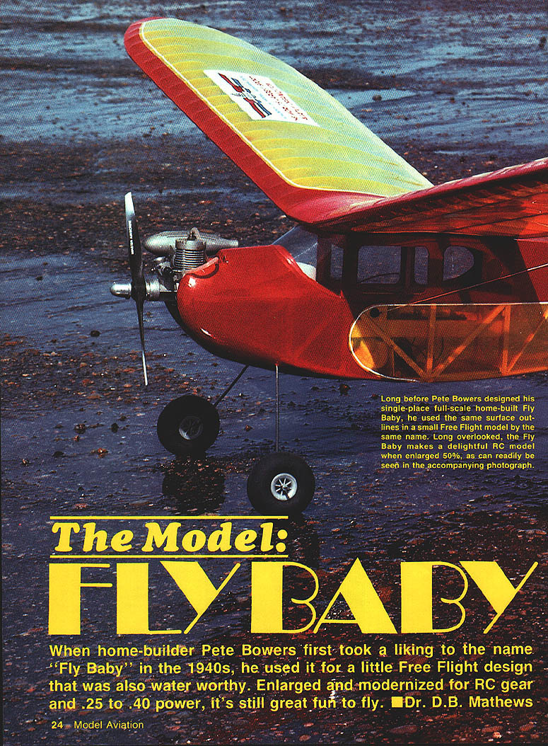
When home-builder Pete Bowers first took a liking to the name "Fly Baby" in the 1940s, he used it for a little free-flight design that was also waterworthy. Enlarged and modernized for radio control and .25 to .40 power, it remains great fun to fly.
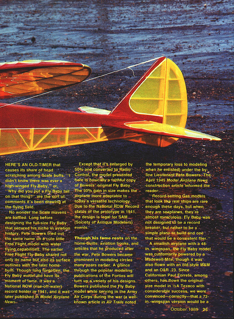
Long before designing the full-size Fly Baby that secured his niche in aviation history, Pete Bowers tried out the same name on a cute little free-flight model with rise-off-water (ROW) capability. The earlier free-flight Fly Baby shared not only its name but also its surface outlines with the later home-built. Though long forgotten by some, the model did have its moment of fame: it was a National ROW record holder in 1941 and was later published in Model Airplane News.
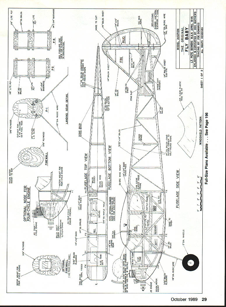
The RC model presented here is basically a faithful copy of Bowers' original Fly Baby, enlarged by 50% (from a 48 in. wingspan to 72 in.) and converted to radio control. The 50% gain in size makes the airplane more adaptable to today's technology. Because of the National ROW record status of the prototype in 1941, the design is legal for SAM (Society of Antique Modelers) events.
Although Bowers' later fame rests on the home-built full-size Fly Baby, aviation books, and postwar articles, he was already prominent in modeling circles in the Forties. He published the Fly Baby while serving in the Army Air Corps under the byline Lieutenant Pete Bowers. As the April 1945 Model Airplane News construction article noted, Fly Baby "was not designed to be a record breaker, but rather to be a simple plane to build and one that would be a consistent flier."
Performance and power
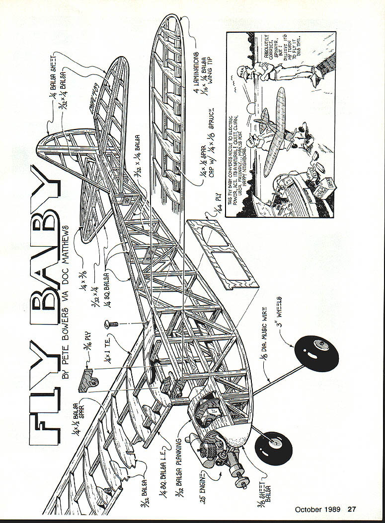
- Wingspan: 72 in. (enlarged 50% from original 48 in.)
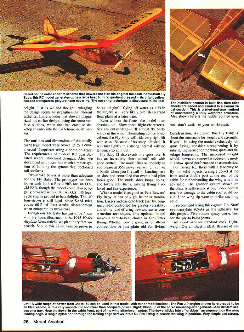
- Recommended power range: .20–.40 cu. in.
- Engines flown on the prototype: Madewell-Mite (original), Fox .19BB, O.S. .25 FSR, O.S. .40 four-cycle
- SAM rules: four-stroke displacement is counted as 60% when compared to two-stroke, so an O.S. .40 four-stroke is still legal under SAM limits
- Flight characteristics: excellent slow-speed handling, superb thermaling ability, steep dihedral gives tight turns without tendency to spin out; short takeoff roll; docile at low power yet strong climb when throttled
The 72-in Fly Baby is delightful both as an Old-Timer contest ship and as a sport flyer. It flies obediently at about 35% power but will climb aggressively at full throttle. Landings are slow and controlled; it performs loops, spins, and graceful stall turns.
Float flying The original 1945 article illustrated floats. Although the present 72-in version has not yet been flown with floats, the plan is to try them. If successful, enlarged float plans may be published later.
Construction
As drawn, this Fly Baby is built to be near minimum weight while retaining strength. If you plan to use the model exclusively for sport flying or expect hard use, consider substituting spruce for the wing spars and fuselage longerons—this increases strength at the expense of some slow-speed performance.
Recommended adhesives and materials
- Instant adhesive: thick-grade Hot Stuff cyanoacrylate (CyA) for most joints
- Ply-to-balsa joints: five-minute epoxy
- Wood: standard stock sizes; lightweight C-grain sheet is ideal
- Ply for window frames and bulkheads: 1/64" ply for window frames, lite-ply for bulkheads; 1/4" ply for certain reinforcements
Notes on wing attachment
- For normal use the grabber system shown on the plans is sufficiently strong.
- For novice RC fliers or those likely to strike solid objects, consider:
- A front dowel and a double post at the rear cabin for rubber-banding the wing, or
- Using rubber bands instead of the grabber.
- The grabber concept is robust and has been used on many designs without failure, but the extra protection from dowels/rubber-bands is prudent for beginners.
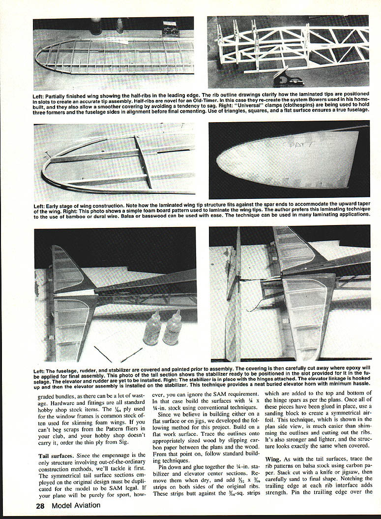
Tail surfaces
The empennage uses a symmetrical section for stabilizer and elevator in order to be SAM legal. If you are building strictly for sport and not SAM events, you may build the surfaces using conventional 1/4" stock techniques.
Method for symmetrical tail surfaces:
- Build on a flat plan work surface. Trace outlines on wood using carbon paper.
- Pin down and glue together the 1/4" stabilizer and elevator center sections.
- While drying, add 3/32" x 3/32" strips on both sides of the original ribs. These butt against 3/16" sq. strips added to the top and bottom of the hinge spars per the plans.
- Once glued, use a sanding block to shape a true symmetrical airfoil.
This method is easier than trimming outlines and cutting out many ribs, produces a lighter and stronger structure, and gives the same covered appearance.
Also shown on the plans: rudder control horn and hinge details.
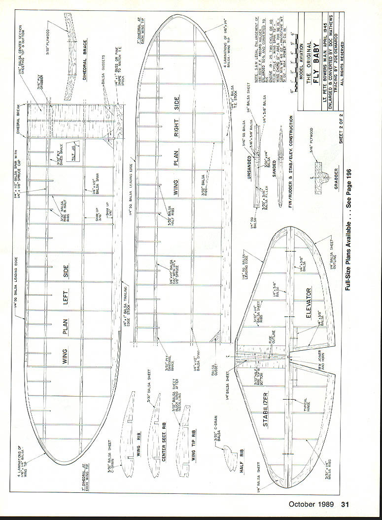
Wing
- Trace rib patterns on balsa stock using carbon paper. Stack-cut with a knife or jigsaw, then sand to final shape.
- Notch the trailing edge at each rib interface for added strength. Pin the trailing edge over the plan and glue ribs in place.
- Add cap strips and spars, then sheet and fair the wing to the ribs, paying close attention to tapered tip sections.
- The center section is built as part of the left wing panel—trim the three center ribs per the center-section rib pattern before adding sheeting.
- Use the tilt jig on the plans to establish the dihedral angle for the panels. If set correctly, block up the tips and sand to final dihedral.
- Cut slots for the 3/32" ply dihedral brace (wing joiner) with a razor saw; epoxy it in place against the back of the main spar.
- After final sanding, check wing alignment and set aside.
Final wing assembly notes:
- Wing tips may be installed with the wing off the board—be careful to avoid warping.
- The wing is secured to the fuselage by bolting through the hardwood center section trailing edge with a single nylon bolt using a trailing-edge Du-Bro fitting. The fore/aft location of the bolt aligns with the Du-Bro bracket mounted in the center of bulkhead F-3.
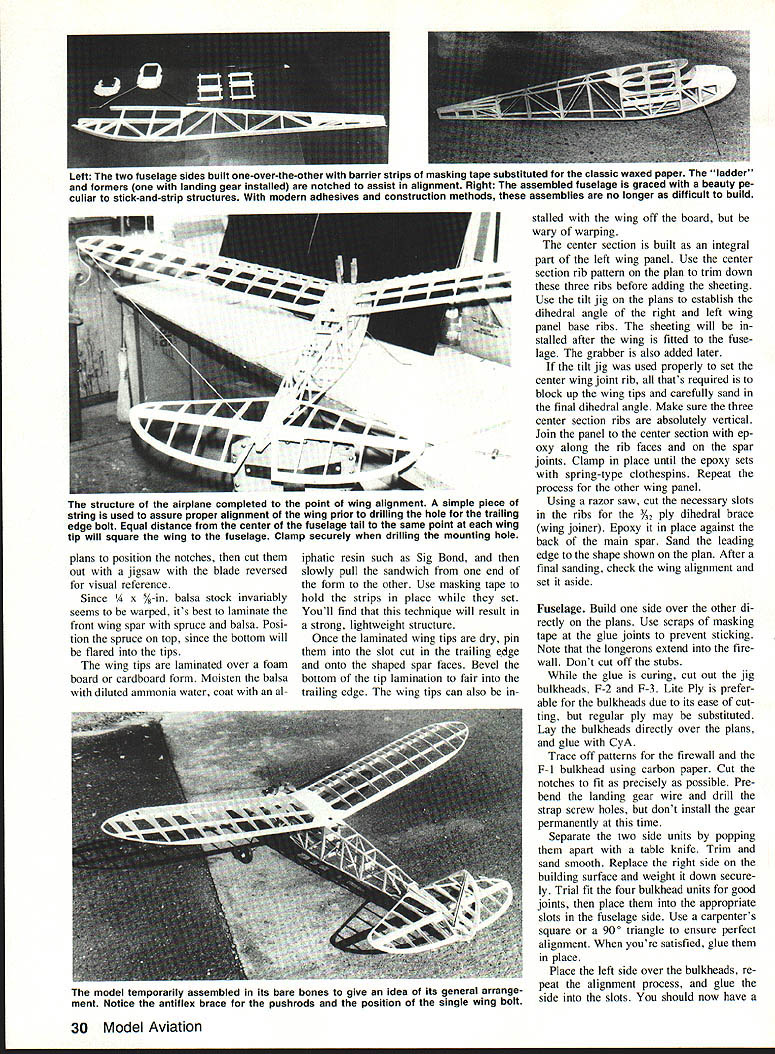
Fuselage
- Build one side over the other directly on the plans. Use scraps of masking tape at glue joints to prevent sticking.
- Leave longerons extending into the firewall—do not cut off the stubs.
- While glue cures, cut out jig bulkheads F-2 and F-3. Lite ply is preferable for bulkheads for ease of cutting.
- Trace and cut the firewall and F-1 bulkhead using carbon paper; fit notches precisely. Prebend landing gear wire and drill strap screw holes but do not install permanently yet.
- Separate side units, trim, and sand. Trial-fit bulkheads for good joints, then glue them into the right-side slots, ensuring alignment with a square.
- Place the left side over bulkheads, align, and glue. You should now have a complete fuselage box.
Tail and tailpost finishing
- Preferred method: leave the rear fuselage on the building board and jack up the tail post so the centerline equals one-half the fuselage width. Cut and install cross braces in pairs.
- Alternate: pull the tail section together over the plan with the box wing saddle. Regardless, ensure the fuselage centerline is straight.
Planking hatch area
- Use stringy sheet balsa soaked in ammonia water. Attach at the base with thick Hot Stuff, curl it over bulkheads with a bead of CyA. Install opposite side the same and join at top by slicing with a straight edge.
Window frames
- Cut from 1/64" ply. Trace from plans, cut out, and glue in place. These provide a hidden seam for installing clear plastic windows later (use R.C. 56 adhesive).
Additional reinforcements
- Epoxy an extra filler piece of basswood or pine into the top of F-3 and the crosspiece at the wing-seat front to reinforce the bracket and grabber.
- Seat the tank on a lite-ply floor with plumbing through the engine-mount cutout. Use standard throttle-control cable.
Bottom sheeting
- Sand to an inside taper prior to installation. Several narrow strips can be used instead of one wide sheet.
Finishing the nose and cabin
- Round the longerons and sand nose blocks to final shape. Cheek-block thickness varies with engine installation—the .25 two-stroke shown has thicker blocks. Thicker cheek blocks add nose weight and narrow the mount.
- Epoxy the front dowel to the cabin roof (used in some wing-retention setups).
Wing-fuselage alignment and grabber
- Drill a 3/16" hole at the center of the hardwood center-section trailing edge; align fore/aft location with the hole in the Du-Bro bracket mounted in F-3.
- Clamp the 3/16" ply grabber against the face of the dihedral brace.
- Pin one end of a heavy string to the center of the rearmost fuselage and use it to check that wing tips are equidistant. Adjust grabber until perfect, then epoxy permanently in place.
The grabber has proven reliable on many designs, but beginners may prefer rubber bands.
Forward cabin roof
- Trace outlines and cut two pieces of 3/32" balsa, noting grain direction. Soak in ammonia water, laminate with thick Hot Stuff, and mold to fit the leading-edge wing contour. Make sure it does not stick to the wing. Reinstall the wing, adjust roof for fit, and glue permanently.
Covering and finish
Preferred method: cover smaller pieces first.
- Cover fin, rudder, stabilizer, and elevator separately; cut hinge slots.
- Cover the fuselage, then cut out stabilizer slot and fin mounting area.
- Cover over windows, then cut away material to install clear plastic later.
Hinge installation
- Slide molded hinges into precut slots and secure with toothpick segments and Hot Stuff.
Color trim and fuel proofing
- The model shown follows Bowers' full-scale color scheme: bright yellow with red trim.
- Trim method used: MonoKote covering, spray red polyurethane (Poly-U) over MonoKote, then lightly buff with No. 400 steel wool.
- Use Sig Stripe-Rite masking tape for curved edges; seal edges against fuel seepage with clear Sig Skybrite (mist on thin coat from 12" or more away for a semi-transparent effect).
- Contrasting trim done with Stripe-Rite tape sealed with clear Skybrite. Vinyl numbers were purchased at an office-supply store.
- Fuel-proof the nose area and tank compartment with clear Skybrite before painting.
Radio installation
- Control rod: stiffen along its length with cross members made from scrap balsa.
- Servo connectors: soldered clevis at the servo end; adjustable clevis at the horn.
- Mount servos on hardwood beams glued to lite-ply with Hot Stuff.
- Battery location: bay between F-1 and F-2 (first bay behind firewall is not easily accessed).
- The model balanced well with RC components positioned as drawn; ensure balance at or slightly forward of the center-of-gravity shown on the plans. Add ballast if needed. Do not fly tail-heavy.
Flying
Preflight checks (do these at home if possible)
- Range check.
- Free surface movement (no binding) and correct control deflections per the plans.
- Engine carburetor needle settings.
- Engine-on radio operation.
- Verify center-of-gravity at or slightly forward of the plan location.
First flight tips
- At the field, head into the wind, add a little right rudder, and advance throttle.
- If you are not airborne within about 12 ft. without adding up elevator, you are taking off downwind.
- Climb rate is mainly a function of engine speed rather than elevator input.
- Fly gently—light control inputs are sufficient. The Fly Baby is forgiving and thermals exceptionally well.
- Try throttling down to very slow flight and feel how it rides light lift; you can even shut the engine off in a thermal.
If you prefer more active flying, try slow-speed touch-and-go landings or sport maneuvers. The Fly Baby will oblige: versatile, brisk, smooth, and responsive.
Whether you're after Old-Timer competition or plain fun-flying, this enlarged, radio-controlled Fly Baby is a delightful, hard-to-beat choice. Run—don't walk—to the workbench.
Pete Bowers
Transcribed from original scans by AI. Minor OCR errors may remain.

