
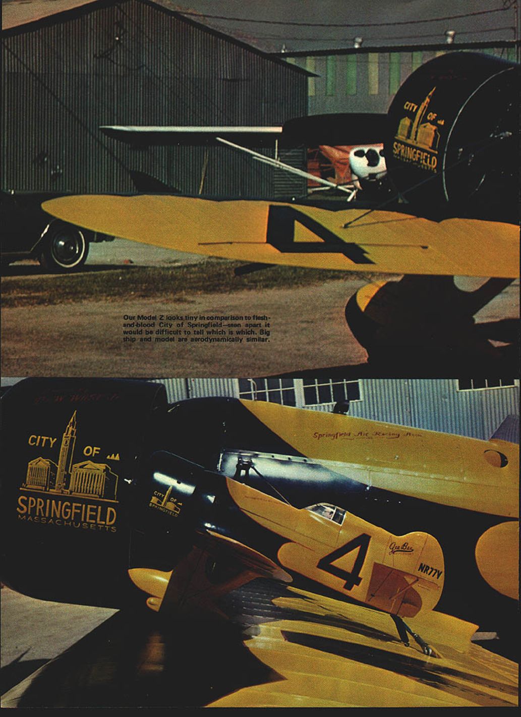
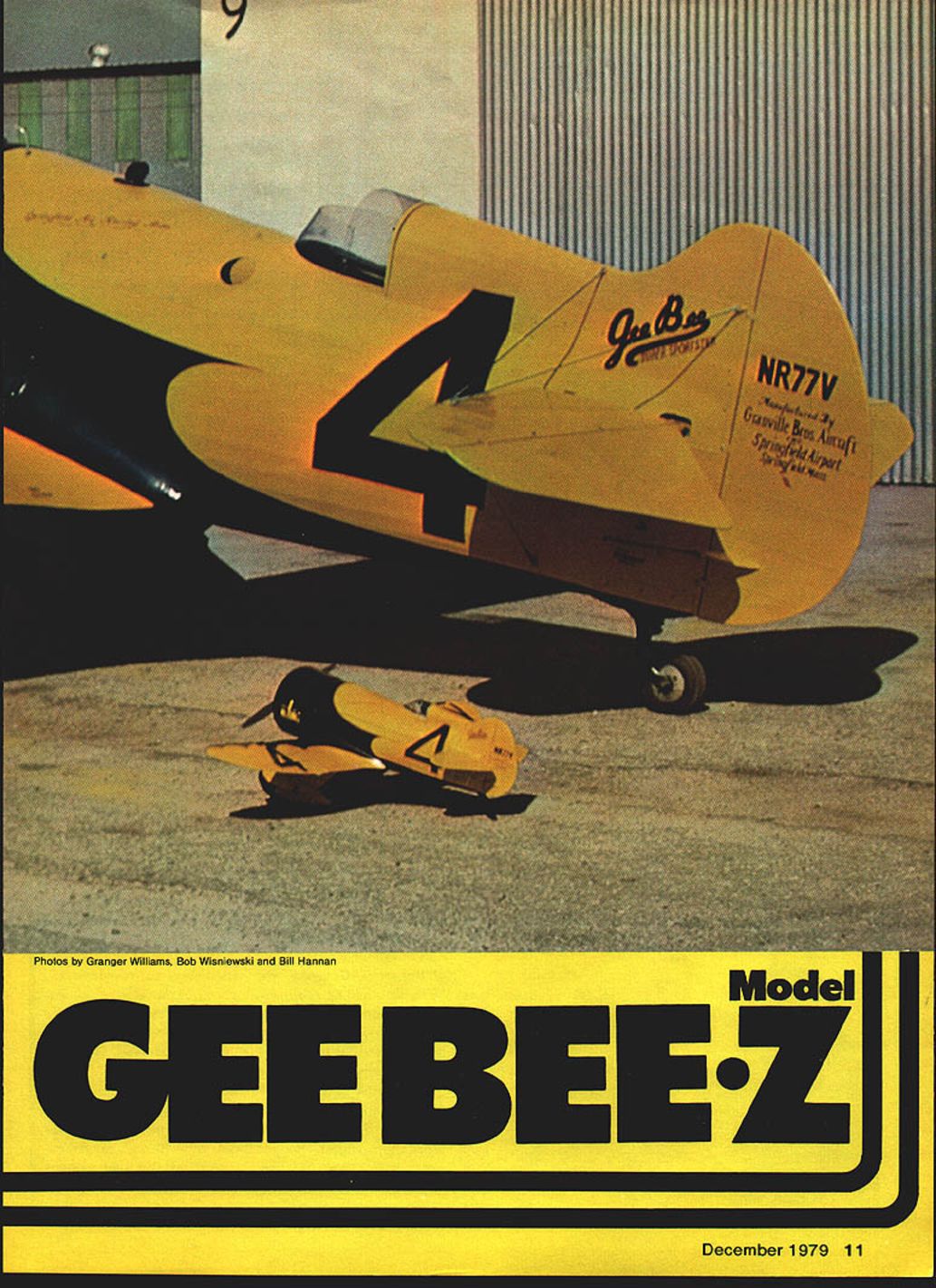
Model Gee Bee Z
The history of aviation has produced only a few men with enough courage to gamble on their convictions: the Wright Brothers, Glenn Curtiss, Tony Fokker, Clyde Cessna, Giuseppe Bellanca, Don Douglas, Walt Beech, Jack Northrop — and the Granville Brothers. The Gee Bees were remarkable aircraft that contributed greatly to the advancement of aerodynamic engineering. Many of the Granvilles' innovations were used in other aircraft for years.
The news media often magnified the misfortunes of aircraft builders, blowing mishaps out of proportion. This sensationalizing of accidents contributed significantly to the downfall of the Granville Brothers Aircraft Company. In most crashes involving Gee Bee aircraft, human failure or pilot error was the primary factor; mechanical failures were secondary. As originally designed and flown, Gee Bee aircraft were good airplanes. Only when modified with greater horsepower and increased fuel tankage did stability problems appear — and those changes were not authorized by the manufacturer.
Contrary to popular belief, Jimmy Doolittle was not the only pilot to fly the Gee Bee R-1, nor was he the only one to fly it multiple times. Russell Boardman test-flew the R-1 several times before Doolittle saw the airplanes. Doolittle also flew the R-1 several times while qualifying for the Thompson Trophy race. Other pilots who flew Gee Bee racers included Lee Gehlbach, Russell Thaw, Roy Minor, and Jimmy Haislip. Lee Gehlbach test-flew the R-2 and flew it in both the Bendix and Thompson races.
The first aircraft produced by the Granvilles in 1929 was a small two-place biplane with side-by-side seating, powered by a 60-hp Velie M-5 engine. One unusual feature was an adjustable wing flap that could be changed in flight to various angles, allowing an unusually low landing speed while retaining good flying performance. The company set up a factory and turned to building Model A biplanes.
Early in 1930 the All American Flying Derby was organized and sponsored by American Cirrus Engines, Inc. The contest required entrants to use Cirrus engines, four-cylinder in-line units manufactured in Michigan under English patents. In Springfield the Granvilles planned a new entry for the derby. An engineer, Bob Hall, had joined the Granvilles in 1929 and, with the rest of the organization, produced the first Gee Bee Sportster, Model X. Many features of this airplane carried through to later Sportsters and racers through 1934. (Bob Hall later turned his design talents to Grumman Aircraft in World War II.)
Model X details: single-place open-cockpit monoplane, 25-foot wingspan, inverted Cirrus engine developing 95 hp at 2,100 rpm. The wing shape used on the Model X was retained in Gee Bee designs through 1933. Pilot Lowell Bayles, experienced from Jennies to Ford trimotors, bought the little sportster after the derby because he was impressed with its performance. Production engines for the Gee Bee X included 95-hp Cirrus model B, 95-hp Menasco model C, 125-hp Menasco model D, 135-hp Ranger model F, and radial-engined versions with the 110-hp Warner model E.
The two-place Senior Sportster, Gee Bee Model Y, was a larger D model (about 20% bigger) designed for engines such as the 210-hp Kinner, 215-hp Lycoming, 240-hp Wright J6, and Pratt & Whitney Wasp Jr.
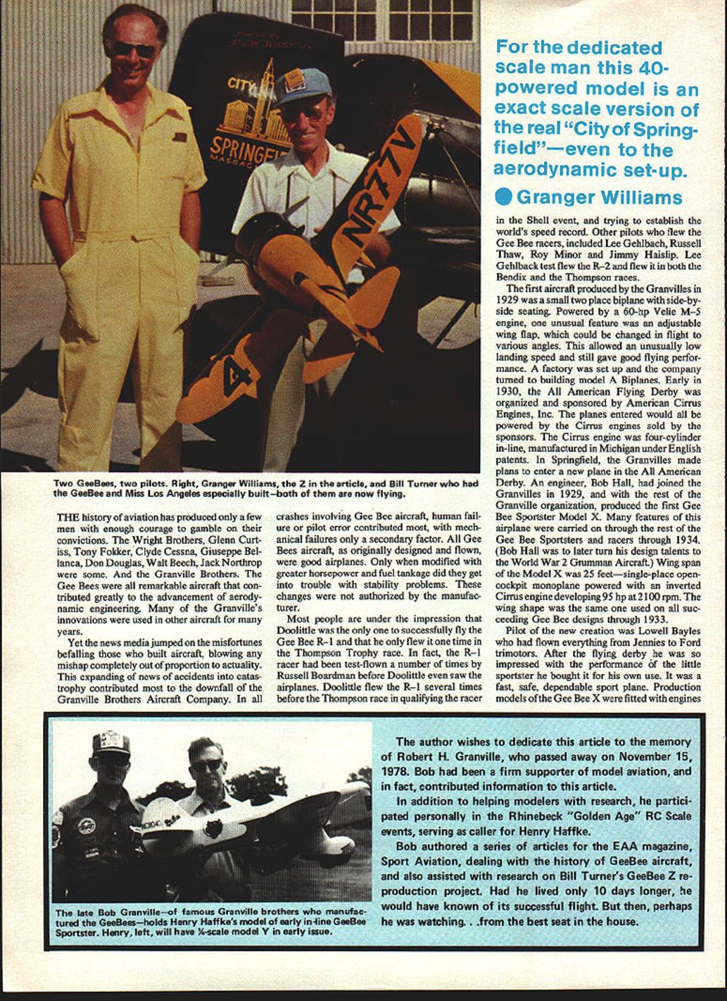
The author dedicates this article to the memory of Robert H. Granville, who passed away on November 15, 1978. Bob was a firm supporter of model aviation and contributed information to this article. He participated personally in the Rhinebeck "Golden Age" R/C scale events, serving as caller for Henry Haffke, and authored a series of articles for Sport Aviation on Gee Bee history. He also assisted with research on Bill Turner's Gee Bee Z reproduction project.
Photographs and captions (notes)
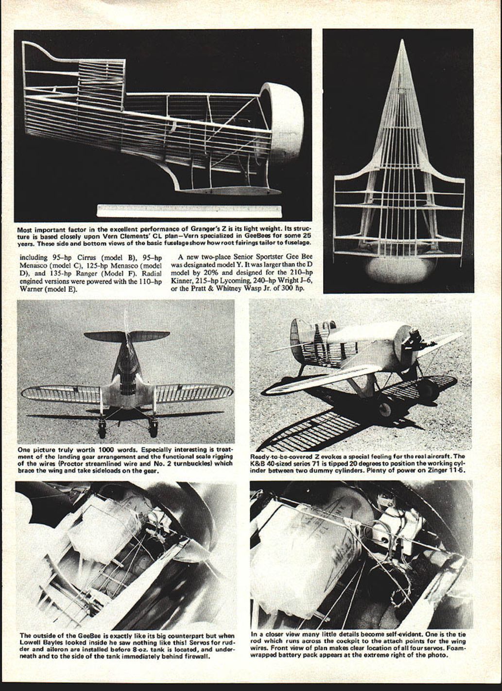
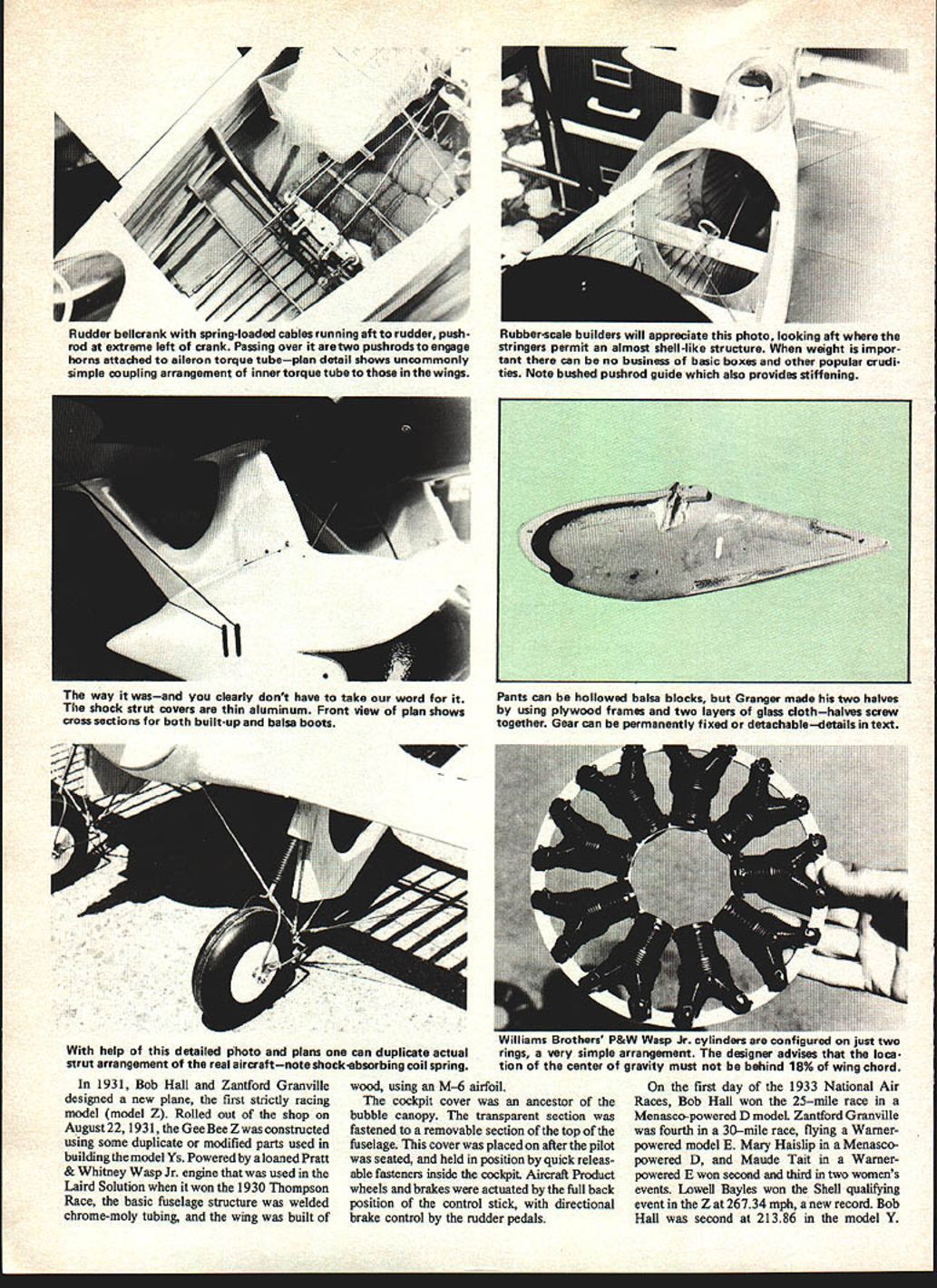
- Most important factor in the excellent performance of Granger's Z is its light weight. Its structure is based closely upon Vern Clements' control-line plan — Vern specialized in Gee Bees for some 25 years. Side and bottom views of the basic fuselage show how root fairings tailor to the fuselage.
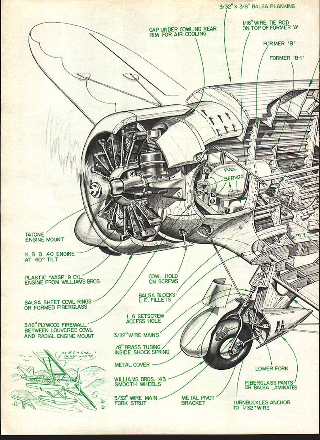
- Outside, the Gee Bee is exactly like its big counterpart. Inside, Lowell Bayles saw nothing like this. Servos for rudder and ailerons are installed up front; an 8-oz. fuel tank is located underneath the side tank immediately behind the firewall. A closer view shows the tie rod running across the cockpit attach points for the wing wires.
- The front-view plan makes clear the location of four servos. The foam-wrapped battery pack appears in the extreme-right photo — a picture truly is worth 1,000 words.
- Especially interesting is the treatment of the landing-gear arrangement: functional scale rigging wires, Proctor streamlined wire, and No. 2 turnbuckles brace the wing to take side loads. The ready-to-cover gear evokes the prototype’s appearance.
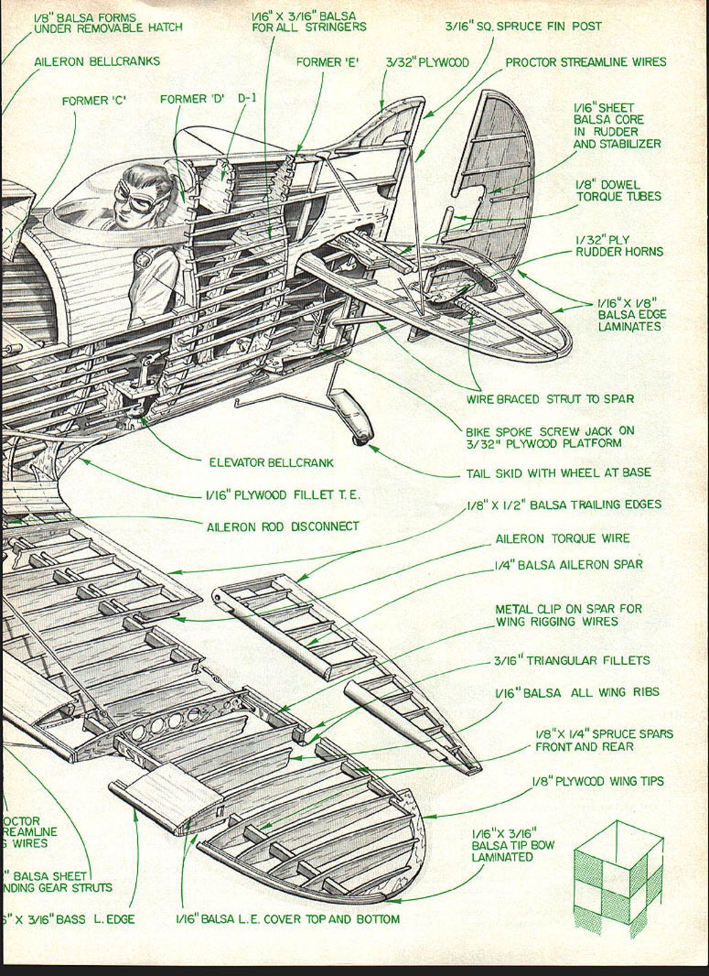
Component callouts (materials and parts)
- 1/8" balsa forms under removable hatch
- 1/16" x 3/16" balsa for all stringers
- 3/16" sq. spruce fin post
- Aileron bellcranks
- Former 'C'
- Former 'D' D-1
- Former 'E'
- 3/32" plywood
- Proctor streamline wires
- 1/16" sheet balsa core in rudder and stabilizer
- 1/8" dowel torque tubes
- 1/32" ply rudder horns
- 1/16" x 1/8" balsa edge laminates
- Wire-braced strut to spar
- Bike-spoke screw jack on 3/32" plywood platform
- Tail skid with wheel at base
- 1/8" x 1/2" balsa trailing edges
- Aileron torque wire
- 1/4" balsa aileron spar
- Metal clip on spar for wing rigging wires
- 3/16" triangular fillets
- 1/16" balsa all wing ribs
- 1/8" x 1/4" spruce spars front and rear
- 1/8" plywood wing tips
- 1/16" x 3/16" balsa tip bow laminated
- 1/16" balsa leading-edge cover top and bottom
- Aileron rod disconnect
- 1/16" plywood fillet trailing edge
- Elevator bellcrank
- Balsa-sheet landing gear struts
---
Gee Bee Z — Full-scale history
In 1931 Bob Hall and Zantford Granville designed a new plane: the first strictly racing model, Model Z. Rolled out on August 22, 1931, the Gee Bee Z used some duplicate or modified parts from the Model YS. It was powered by a loaned Pratt & Whitney Wasp Jr. engine — the same engine used in the Laird Solution when it won the 1930 Thompson Race. The basic fuselage structure was welded chrome-moly tubing; the wing was built of wood using an M-6 airfoil.
The cockpit cover was an ancestor of the bubble canopy. The transparent section was fastened to a removable section of the top of the fuselage and placed on after the pilot was seated, held by quick-release fasteners inside the cockpit. Aircraft Products wheels and brakes were actuated by full-back position of the control stick, with directional brake control by the rudder pedals.
On the first day of the 1933 National Air Races, Bob Hall won the 25-mile race in a Menasco-powered D model. Zantford Granville was fourth in a 30-mile race flying a Warner-powered Model E. Mary Haislip (Menasco D) and Maude Tait (Warner E) placed second and third in two women's events. Lowell Bayles won the Shell qualifying event in the Z at 267.34 mph, a new record; Bob Hall was second at 213.86 mph in the Model Y. Mechanical and engine problems kept some competitors from completing the required four passes over the course.
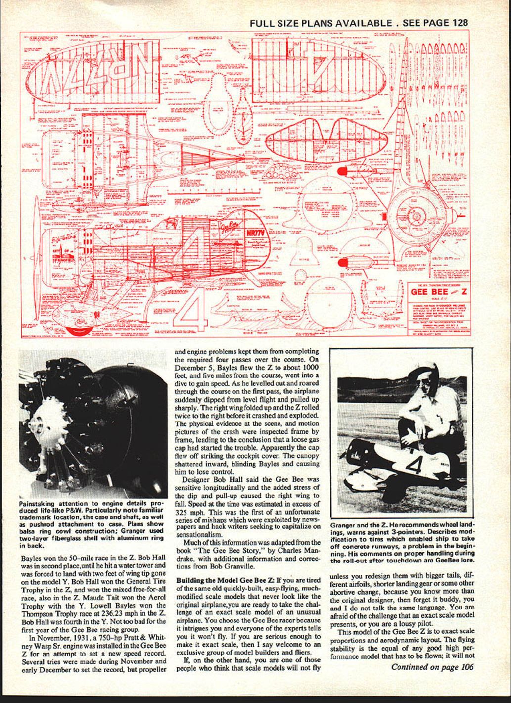
On December 5, Bayles flew the Z to about 1,000 feet and, five miles from the course, went into a dive to gain speed. As he leveled out and roared through the course on the first pass, the airplane suddenly dipped from level flight and pulled up sharply. The right wing folded up; the Z rolled twice to the right before it crashed and exploded. Physical evidence at the scene, and motion pictures of the crash inspected frame by frame, led to the conclusion that a loose gas cap had started the trouble. Apparently the cap flew off and struck the cockpit cover. The canopy shattered inward, blinding Bayles and causing him to lose control.
Designer Bob Hall said the Gee Bee was sensitive longitudinally and that the added stress of the dip and pull-up caused the right wing to fail. Speed at the time was estimated in excess of 325 mph. This was the first of an unfortunate series of mishaps that newspapers and sensationalist writers exploited.
Much of this information was adapted from The Gee Bee Story by Charles Mandrake, with additional information and corrections from Bob Granville.
---
Building the Model Gee Bee Z
If you are tired of the same quickly-built, easy-flying, much-modified scale models that never look like the original airplane, you are ready to tackle an exact-scale model of an unusual airplane. You choose the Gee Bee racer because it intrigues you and everyone says it won't fly. If you are serious about making it exact scale, welcome to an exclusive group of model builders and fliers.
If, on the other hand, you believe scale models will not fly unless you redesign them with bigger tails, different airfoils, shorter landing gear, or other changes because you "know more than the original designer," then this is not for you. An exact-scale Gee Bee is a challenge; it will punish sloppy piloting.
This model of the Gee Bee Z is built to exact scale proportions and aerodynamic layout. Its flying stability equals any good high-performance model that must be flown actively; it will not fly itself, but it has no bad habits. Landings are best made as wheel landings — do not attempt three-point landings. Quick rudder action on rollout is necessary to avoid ground loops on asphalt or other hard surfaces when the tail-wheel contacts the ground. A small tail-wheel is built into the end of the tail-skid for hard-surfaced runways.
I was unable to fly the airplane off asphalt or concrete until special tires were made by grinding a groove in regular tires and snapping on an O-ring of polypropylene. Allowing the tires to slide prevented further wheel problems. Full back stick is required to keep the tail down as you open the throttle; then ease the stick forward as speed increases. The ship comes off with a little back stick in 30 to 50 feet depending on wind and weight.
After takeoff let it accelerate to 70–80 mph. Small corrections will keep it flying level. Do not try to climb too soon or rotate aggressively; let it gain speed and then climb slowly. The Z is very sure-footed in the air and will do most anything you ask of it, but it will punish a sloppy pilot on landing. Special tires are not necessary for dirt or grass.
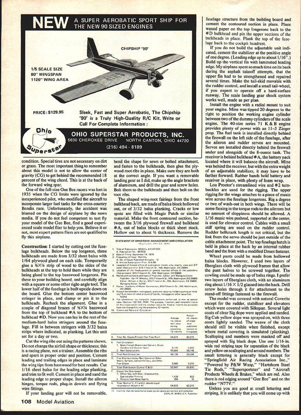
The most important thing to remember about this model is not to allow the center of gravity (CG) to get behind the recommended 18 percent of the wing chord (this is at the back of the forward wing spar). One full-size Gee Bee racer was lost in 1935 when CG limits were ignored after the aircraft was modified to carry larger fuel tanks for the Bendix cross-country race. The accident was unfairly blamed on the airplane's design by the news media. If you do not feel competent to test-fly your model Gee Bee, find an experienced scale model flier to assist you. Many expert pattern fliers are not qualified to fly this airplane.
Construction (step-by-step)
- Cut the fuselage bulkheads. Below the top longeron, these bulkheads are made from 3/32" sheet balsa with 1/64" plywood glued on each side.
- Temporarily glue a 1/8" x 1/4" strip of wood to the sides of the bulkheads at the top to hold them while being glued to the top basswood longerons.
- Pin the assembly to the building board and align squarely. Build the lower half of the fuselage upside down. Glue the bottom center basswood stringer in place and clamp or pin it to the bulkheads; recheck alignment.
- Glue in diagonal braces of 1/8" x 1/4" basswood from the top of bulkhead #A to the bottom of bulkhead #D. Lay in the rest of the medium-hard balsa stringers around the fuselage. Fill between stringers with 3/32" balsa strips where indicated as planking. Let this unit set for a day or two.
- Cut wing ribs using the patterns shown. Do not change the airfoil shape or thickness — this is a racing plane, not a trainer. Assemble ribs and spars in proper order and position. Cement leading and trailing edges in place and laminate wing tips from basswood for best results.
- Cut 1/16" sheet balsa for leading-edge planking; trim, cement, and sand to shape. Install aileron hinges, torque rods, plug-in dowels, and flying-wire fittings.
- If the landing gear will be non-removable, bend the required shape for sewn or bolted attachment and fasten to the bulkheads, then glue the plywood root ribs in place, ensuring correct angles. For removable gear, make aluminum angle brackets, drill gear and screw holes, bolt to bulkheads, then bolt on the root ribs.
- Shape wing-root fairings from balsa block hollowed out, or from 3/32" balsa planking. Fill cracks or low spots with Magic Patch or similar material.
- Make the front contoured section between the 3/16" plywood firewall and bulkhead #A from balsa blocks or thick sheet stock; hollow out to about 1/8" thickness. Remove fuselage from the building board and cement the contoured section in place.
- Place waxed paper on the top longerons back to the #D bulkhead and pin the upper sections of the bulkheads in place. Plank the top of the fuselage back to the cockpit headrest.
- If not building the adjustable stabilizer unit, cement the stabilizer at a positive angle of about one degree (leading edge up about 1/16").
- Build up the vertical fin with a laminated leading edge. Make the tail-skid movable with the rudder control and install a small tail-wheel for hard-surface operation. The scale landing gear shock system works well if built per plan.
- Install the engine with a radial mount suitable for your motor. Mine was tipped 20 degrees to the right to position the working engine cylinder between two dummy cylinders of the scale engine. A .40-size series 71 K&B engine provides plenty of power with an 11x5 Zinger prop.
- Install the fuel tank directly behind the firewall on the left side of the fuselage after mounting the aileron and rudder servos. Servos are installed directly behind the firewall under and alongside the 8-ounce tank. Place the receiver behind bulkhead #A; the battery pack should be located where it will balance the aircraft. Rubber bands and foam wrap secure electronics.
- Use Lou Proctor's streamlined wire and #2 turnbuckles for rigging. Upper wing rigging attaches to a piece of music wire across the fuselage longerons. Rig in a degree or two of washout in both wings.
- Use a 1/16" music wire pushrod, supported at the center, for elevator control. Use cables with a small stiff spring for rudder control. Rudder bellcrank length is not critical, but the servo linkage should be just outside the cable attachment point.
- The fuselage hatch is held at the back by an internal rubber band and at the front with a modified Dzus fastener.
Cowling, wheel pants, and finishing
- Wheel pants: can be made from hollowed balsa blocks or from two layers of fiberglass cloth with plywood frames that allow pant halves to be screwed together.
- Cowling: balsa rings or two layers of fiberglass cloth with an aluminum ring (about 1/16" x 1/2") glassed into the back. Drill screw holes through the ring for attachment to stand-off fittings on the firewall.
- Covering: natural Coverite for most surfaces; Silkspan for rudder, stabilizer, and elevators. Apply several light coats of clear Sig dope and sand. Spray Sig Cub yellow dope with three coats lightly sanded; the weave of the cloth should still be visible except where metal covering is simulated.
- Scalloping and numbers: mask and spray with Sig black dope. Use one 1/16" red striping tape to separate black and yellow on scalloping and around numbers. Small lettering is generally black except for a few red items: "Springfield Air Racing Association Inc.," "Powered by P&W Wasp," "Hartshorn Steel Tie Rods," "Superstrops," and "Aircraft Products Wheels & Brakes." Also red edging appears around "Gee Bee" and on the rudder marking "N7747."
Unless you are good at small lettering and striping, it is unlikely you will produce proper style, size, or color of decals. The author found only black lettering and a poor style match. Decals (except wing numbers) and fiberglass cowling and wheel pants are available from Bob Holman Plans.
For questions, send a stamped, self-addressed envelope with your letter and reasonable questions to: Granger Williams Gee Bee Z 181 Pawnee St. San Marcos, CA 92069
Please be patient and do not expect an instant answer.
Plans and sources
- The drawings presented were traced from control-line drawings by Vern Clements with scale data supplied by Premo Galletti. Vern Clements is a long-time Gee Bee enthusiast and model builder who won the control-line Nationals with a Gee Bee R-1 and built 1" scale gliders to test stability theories.
- Control-line drawings of the Gee Bee Z (2" scale) and R-1 (1½" scale) may be obtained from Vern Clements at: P.O. Box 608, Caldwell, ID 83605. Include a stamped envelope for his price list.
- Much full-scale Gee Bee information was taken from The Gee Bee Story by Charles Mandrake. For further reading, contact Charles Mandrake, P.O. Box 955, Ashtabula, OH 44004 for his book National Air Races 1932; send a stamped envelope for prices.
- Additional Gee Bee information was obtained from Bob Granville, Henry Hanke, Tom Nallen, and Rudy Profant.
Acknowledgment: Much of the material for this article was adapted from The Gee Bee Story by Charles Mandrake, with additional information and corrections contributed by Bob Granville.
Transcribed from original scans by AI. Minor OCR errors may remain.

