
The Model: Laser 200
The Story
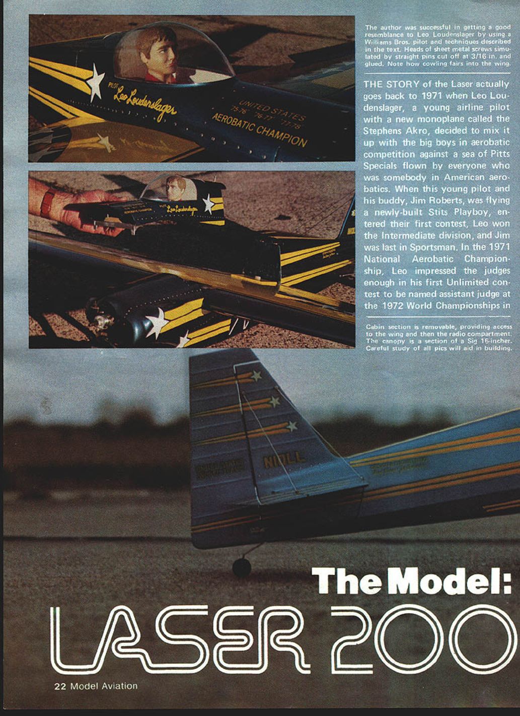
The story of the Laser actually goes back to 1971 when Leo Loudenslager, a young airline pilot with a new monoplane called the Stephens Akro, decided to mix it up with the big boys in aerobatic competition against a sea of Pitts Specials flown by everyone who was somebody in American aerobatics. When Leo and his buddy Jim Roberts flew a newly built Stits Playboy and entered their first contest, Leo won the Intermediate division and Jim was last in Sportsman. In the 1971 National Aerobatic Championship, Leo impressed the judges enough in his first Unlimited contest to be named assistant judge at the 1972 World Championships in France—where he gained valuable experience.
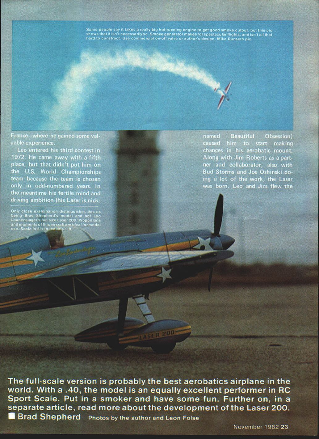
Leo entered his third contest in 1972 and came away with a fifth place, but that didn't put him on the U.S. World Championships team because the team is chosen only in odd-numbered years. In the meantime his fertile mind and driving ambition (his Laser is nicknamed Beautiful Obsession) caused him to start making changes in his aerobatic mount. Along with Jim Roberts as partner and collaborator, and with Bud Storms and Joe Oshinski doing much of the work, the Laser was born. Leo and Jim flew the Laser full scale.
The full-scale version is probably the best aerobatics airplane in the world. With a .40, the model is an equally excellent performer in RC Sport Scale. Put in a smoker and have some fun. Further on, in a separate article, read more about the development of the Laser 200.
Brad Shepherd Photos by the author and Leon Folse
Jim then decided to build his own Laser, which first flew in 1978. There is very little difference between the two aircraft. Jim's has a shorter landing gear, a slightly different cowl, and a different paint scheme (both planes are basically metallic blue with light yellow trim, but the trim and stars on Jim's are different than on Leo's).
Both Lasers would represent the United States in the World Championships in 1982 in Europe, as Leo took another first in Unlimited and Jim came in fourth at the National Aerobatic Championships in Sherman, TX in October the previous year. Henry Haigh, who flew a modified Stephens called Super Star (much the same as the Lasers), would also be in the World Champs; he was runner-up to Leo at the Nationals.
Permit me to take a short look back to a somewhat prophetic statement made by Don Berliner in a 1973 article on aerobatic airplanes, referring to the Stephens Akro: "One of these days something is going to come along to knock the Pitts off its lofty perch." That day appears to have arrived, with three out of the top five at the Nats flying versions of the original Stephens.
So much has been written about the exploits of Leo and the Laser that I couldn't add anything new of substance. However, I had the pleasure of meeting Leo and Jim during the 1981 National Championships at Sherman, and I found out that both of them fly RC. During low-ceiling weather (when the full-size planes were grounded) they both flew the model I had taken with me, a modified Stephens with a smoker for "kicks" (Super Akro "Chips" — June 1981 MA). I don't know if they ever plan on entering RC competition, but keep an eye on them if they do.
The model
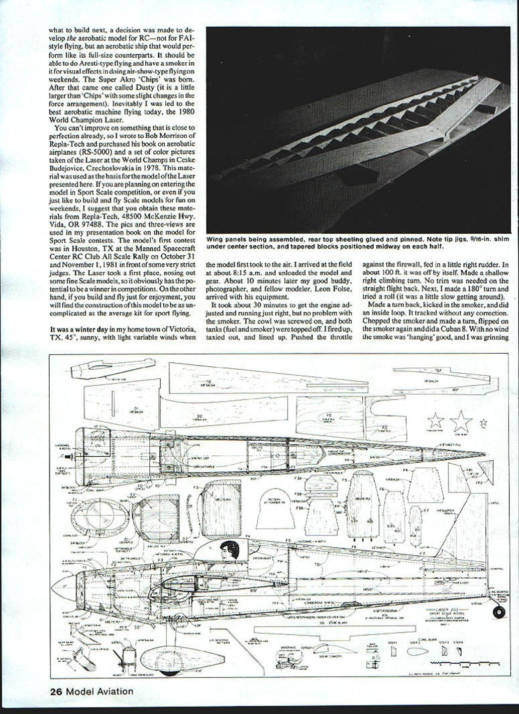
A few years back, while mulling over what to build next, the decision was made to develop an aerobatic model for RC — not FAI-style flying. An aerobatic ship would perform like its full-size counterparts, should be able to do Aresti-type flying, have a smoker for visual effects, and be suitable for air-show-type flying on weekends.
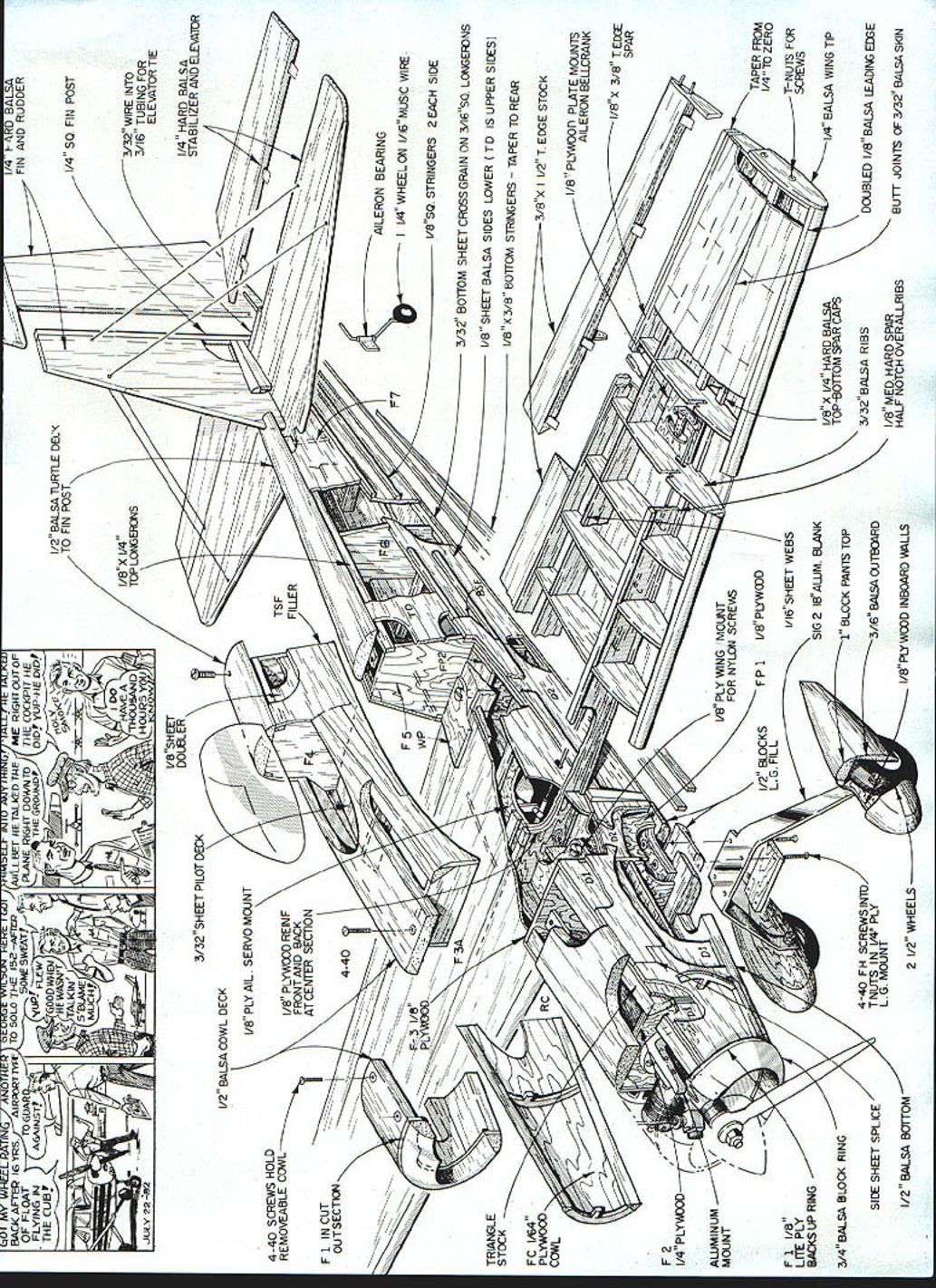
This page contains the full-page exploded-view drawing (plans) of the Laser 200 with part labels and construction callouts. There is no continuous article text to transcribe that continues the main article.
It was a winter day in my home town of Victoria, TX, 45° and sunny with light variable winds, when the model first took to the air. I arrived at the field about 8:15 a.m. and unloaded the model and gear. About 10 minutes later my good buddy, photographer, and fellow modeler Leon Folse arrived with his equipment.
It took about 30 minutes to get the engine adjusted and running just right, but no problem with the smoker. The cowl was screwed on, and both tanks (fuel and smoke) were topped off. I fired up, taxied out, and lined up. Pushed the throttle against the firewall and fed in a little right rudder. In about 100 ft. it was off by itself. A shallow right climbing turn required no trim on the straight flight back. Next, I made a 180° turn and tried a roll (it was a little slow getting around).
I turned back, kicked in the smoker, and did an inside loop. It tracked without any correction. I chopped the smoker and made a turn, tripped the smoker again and did a Cuban 8. With no wind the smoke was "hanging" good, and I was grinning from ear to ear.
I went straight out, cut off the smoker, made a turn, dove a little, started the smoke, and did a knife-edge across the field. I'd never had a model fly this well on a test flight.
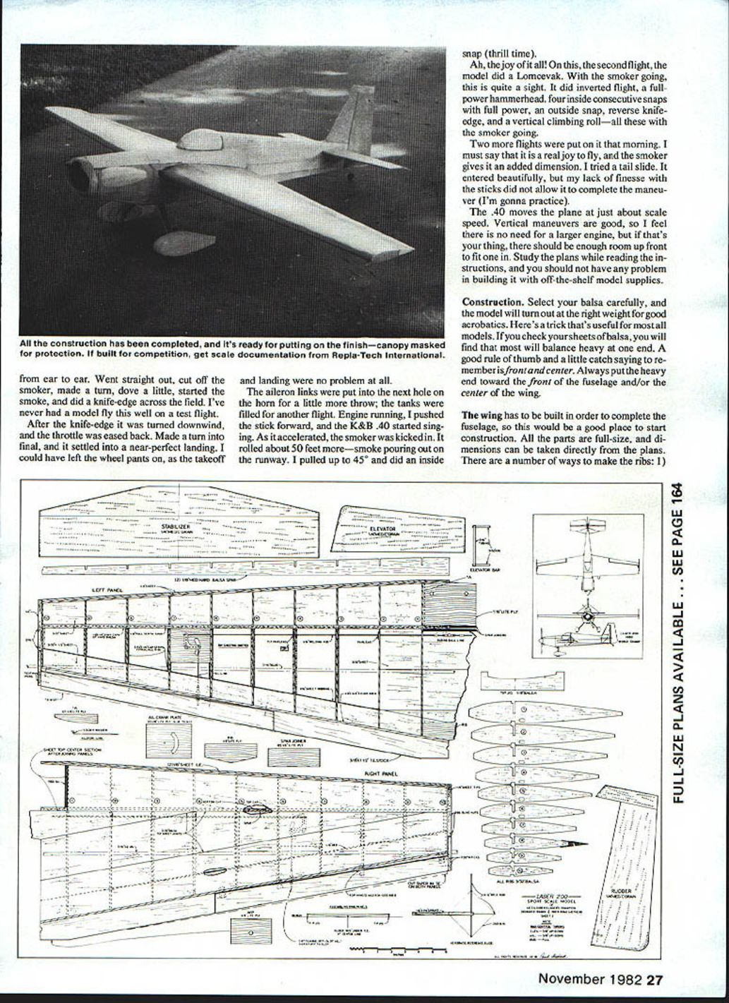
After the knife-edge it was turned downwind and the throttle was eased back. I made a turn into final and it settled into a near-perfect landing. I could have left the wheel pants on, as the takeoff and landing were no problem at all.
The aileron links were moved to the next hole on the horn for a little more throw; the tanks were filled for another flight. Engine running, I pushed the stick forward, and the K&B .40 started singing. As it accelerated, the smoker was kicked in. It rolled about 50 feet more — smoke pouring out on the runway. I pulled up to 45° and did an inside snap (thrill time).
On the second flight the model did a Lomcevak with the smoker going — quite a sight. It did inverted flight, a full-power hammerhead, four inside consecutive snaps with full power, an outside snap, reverse knife-edge, and a vertical climbing roll — all with the smoker going.
Two more flights were put on that morning. It is a real joy to fly, and the smoker gives it an added dimension. I tried a tail slide: it entered beautifully, but my lack of stick finesse did not allow completion of the maneuver (I'm gonna practice).
The .40 moves the plane at just about scale speed. Vertical maneuvers are good, so there is no need for a larger engine, but if that's your thing, there should be enough room up front to fit one in. Study the plans while reading the instructions, and you should not have any problem building it with off-the-shelf model supplies.
Construction
Select your balsa carefully, and the model will turn out at the right weight for good aerobatics. Here's a trick useful for most models: most sheets of balsa will be heavier at one end. A good rule of thumb — front and center — is to put the heavy end toward the front of the fuselage and/or the center of the wing.
The wing must be built to complete the fuselage, so start construction there. All parts are full-size; dimensions can be taken directly from the plans.
Ribs and spar
There are a number of ways to make the ribs:
- Trace the rib patterns onto balsa and cut each rib individually from the template.
- Use carbon paper over the balsa for direct transfer.
- Use the root and tip ribs with about 10 blanks of balsa stacked for carving. In the latter method, put the tip rib on the outside of one end of the stack and the root rib between the first and second pieces. I use 1/16 ply patterns of the root and tip ribs when carving this way.
Cut the spar pieces from the same piece of straight-grained balsa to ensure uniformity. Pin a piece of hard 1/8 x 1/4 balsa over the plans as shown for the spar cap. Glue the spar to the rear edge of this with the slots up, keeping it 90° to the workbench. Check the fit of each rib and trim where necessary. Pin over the plans to the 1/8 square jig and a straight piece of 1/8 x 1/4 as the inside piece of the leading edge. Check-fitting again; when OK, glue them in place, pinning securely to the jig.
Cut a sheet of 3/32 x 3 x 31 medium C-grain balsa in half along the length for the trailing edge sheets. Glue a piece of 1/8 x 3/8 balsa to the edge of each of these sheets at a 90° angle. Note the side view of the fuselage drawing which shows the root rib, and also rib #8 on the wing plan. Glue the trailing edge sheet to the rear of the rib, firmly butting the 1/8 x 3/8 against them.
Check-fit a piece of hard 1/8 x 1/4 balsa on top of the spar; this cap must fit flush with the ribs. Glue in place when fitted. Lay a piece of medium A-grain 3/32 sheet over the ribs in front of the spar. Sand an angle to the edge so it fits the 3/16-in. leading edge piece. Mark the excess over the rear edge of the spar and trim it off. Glue and pin the sheet in place, making sure the ribs are still pinned down firmly to the 3/16-in. jig. Use slower-drying cabinet-type glue over the ribs and model-type cement along the leading edge, as a dope-type finish was employed on the model.
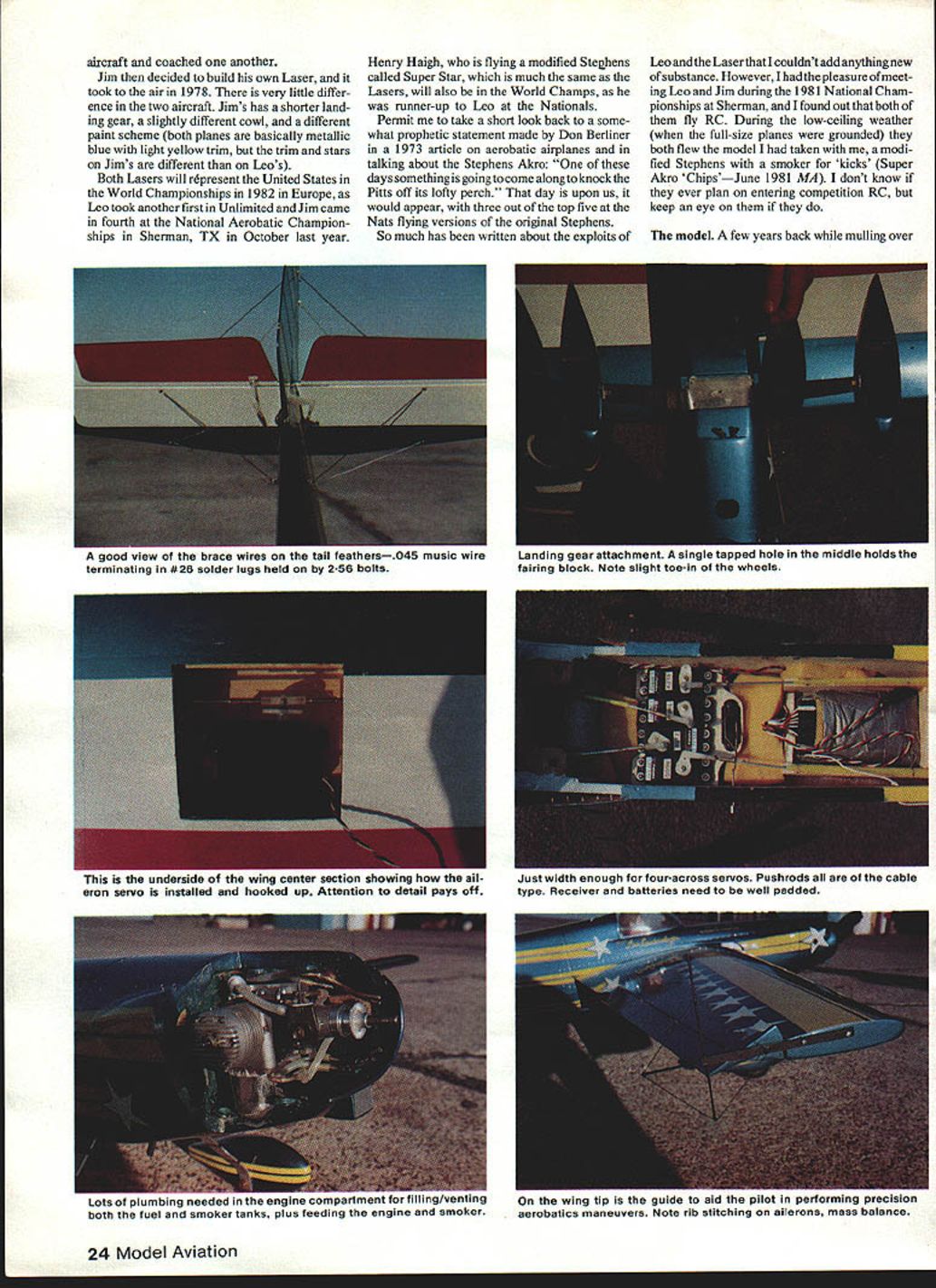
Cut the aileron crank plate from 1/8 Lite Ply, then mount the crank. Cut the fairleads for the pushrod from 1/16 ply. The pushrods are made from 1/16-in. copper-coated welding rod (it doesn't rust, solders well, and bends easily). Make the bend for the aileron crank, slip it onto the crank, slide it through the holes in the ribs (slipping the fairleads on as you go), then glue the aileron crank plate at the cutouts in ribs 6 & 7. Cut and glue the 3/32 x 1/4 cap strips to the ribs. Don't sheet the center section at this time. When the glue has dried on the panels, unpin from the workbench.
Assembling the wing panels
Use an inside flush door to assemble the panels into a full wing; these doors are flat, straight, and pins push easily into them.
- Draw a straight line 6 ft. long; about 6 in. from one edge of the long side.
- Draw a line at 90° to the 6-ft. line at its center.
- Draw two more lines at 90° to the long line spaced 29 5/8 in. each side of the center line; pin the tip jigs to these lines.
- Place a scrap piece of 3/32 sheet where the center line crosses the long line. Make sure the lines on the jigs match the long centerline; this builds the proper tip washout into the wing.
- Pin the panels down at the center section, lining up the rear edge of the spar over the long line and the mark on the tip jig. Place a 9/16-in. shim under the trailing edge at the center section and pin down. About halfway out on each panel at the trailing edge, shim to assure a straight trailing edge when the top sheeting is glued on.
Epoxy the ply joiners to the spar and the ply piece RB to the trailing edge. Choose matching sheets of 3/32 balsa for the top sheeting to have a balanced wing and avoid adding weight to one tip. Fit and trim the top sheeting according to the drawing of the right panel. Be very careful when gluing the top sheeting on, as the wing is almost impossible to twist (or untwist) once this sheeting is in place. Don't sheet the center section over the leading edge yet.
When the sheeting glue has thoroughly dried, remove the wing from the board and turn it over. Epoxy ply 1A ribs to the inside of #1 ribs flush with the bottom curve. Sheet the bottom center section behind the spar. Glue the 1/8 balsa webs between ribs at the leading edge of the trailing edge sheet. Turn the wing over and epoxy the 1/4 ply plate in place over ribs 1A. Sand the 1/8 trailing edge flush with the top sheeting.
Pin one panel down to the bench along the trailing edge over wax paper or poly sheet. Take the 3/8 x 1 1/4 trailing edge stock and check-fit it to the 1/8-in. trailing edge. Sand where needed for a tight fit, cut the proper angle at the center section, and glue and pin to the wing. Repeat for the other panel. Using a long straightedge, trim the trailing edge stock as shown on the plans. Sand the trailing edge so it makes a smooth transition from the wing sheeting. Lay out the ailerons with a ball-point pen and cut them away. Sand the angle to the leading edge of the ailerons as shown on rib #8 of the wing drawing.
Sand the 1/8-in. leading edge piece flush with the sheeting. Cut a piece of 1/16-in. sheet a little wider than the leading edge and glue it to the wing to complete the 1/4-in.-thick leading edge. This laminated leading edge is stronger than a one-piece leading edge, less susceptible to warping, and easier to sand due to the glue joint acting as a guide. Glue on 1/4 sheet tips, but don't glue the portion that makes up the aileron mass balance. Sand the tips to shape around the tip rib, then cut off the aileron mass balance. Glue the balance in place and pin with toothpicks to the aileron.
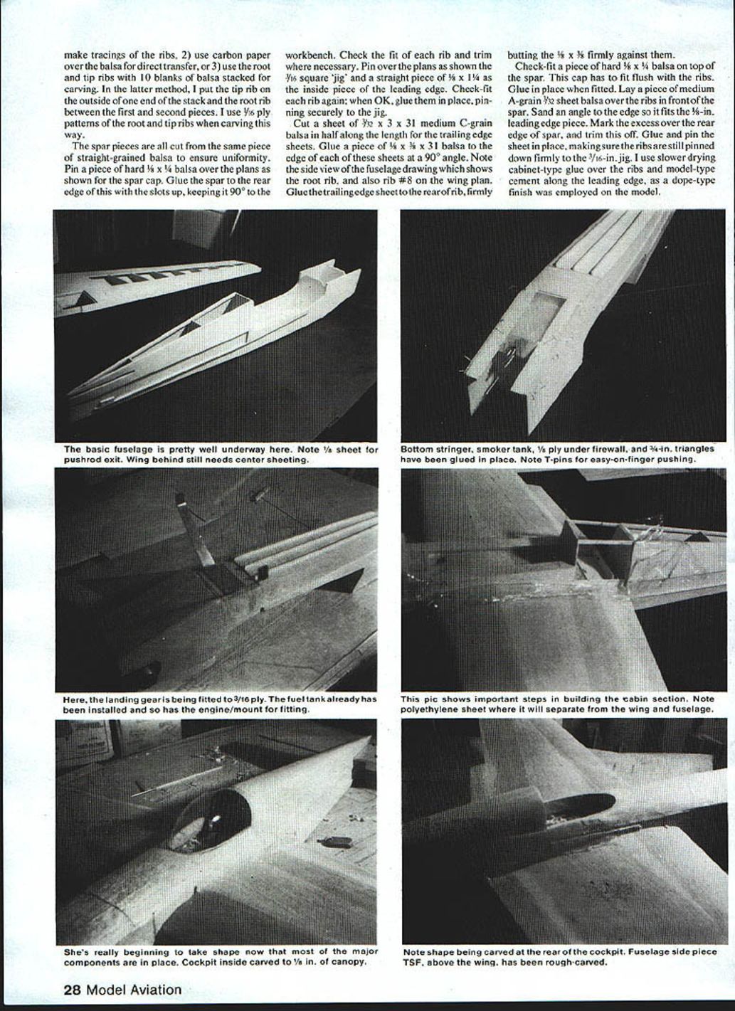
Fuselage
If you have access to 1/16 x 6 x 48 sheets of balsa, it makes the job of fuselage side fabrication easier. If not, glue two sheets of 1/16 x 3 x 36 together to form six-inch sheets; do this three times as there is a side joint to be made. Cut two 6 x 8 pieces from one of the sheets. Make a dovetail joint on one end of the 1/2 x 6 x 36 sheets as shown on the side view of the fuselage plans, then make a matching joint on the two 6 x 8 pieces. Glue together for the basic sides.
Lay out the thrust line on one sheet with a ballpoint pen and use this as a reference point while laying out the side. Refer to the isometric sketch and the arrows on the side view as the layout is made. When the layout is completed, cut the side out and use it as a pattern to make the other side.
Cut the doublers from 1/8 sheet and glue to the sides. Glue the 3/16 sq. longerons to each side, then cut the cabin section of the sides away (set aside for the time being).
Pin sides over the top view from the rear of the landing gear plate to the tail post. Slide each former down in its place and pin. Use a 90° triangle to make sure sides are square to the work surface. Cyanoacrylate glues come in handy here. After the formers are glued in place, glue the top 3/8 x 1/4 longerons into their cutouts. Pull in the top 3/8-in. of the sides where the cockpit is; glue the sides to the top longeron and to the cabin formers. Cut a 1/8 ply former and glue in place forward of F1. Glue the motorbox together and glue the blocks in the nose to true the top of the fuselage.
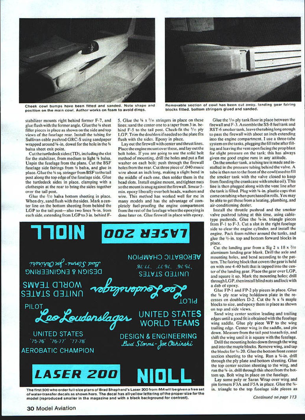
Glue the stabilizer mounts right behind former F-7, and glue flush with the former angle. Glue the 1/8 sheet filler pieces in place as shown on the side and top views of the fuselage rear. Install the tubing for Sullivan cable pushrod GRC-S using sandpaper wrapped around 1/8-in. dowel for the hole in the 1/8 balsa sheet exit point.
Cut the turtledeck sides (TD), including the slot for the stabilizer, from medium to light 1/8 balsa. Unpin the fuselage from the plans. Cut the BSF fuselage side fairings from 1/8 balsa and glue in place. Glue the 1/8 sq. stringer from BSF to the tail post along the top edge of the fuselage side. Glue the turtledeck sides in place, clamping with a clothespin at the rear to bring the sides together over the tail post.
Glue the 3/32 balsa bottom sheeting in place. When dry, sand flush with the sides. Mark a center line on the bottom sheeting from behind the LGP to the tail post — also mark two lines 5/16 in. from each side, extending from the LGP to 3 in. behind F-5.
- Glue the 1/8 x 5/16 stringers in place on these lines; sand the center one to a taper from 3 in. behind F-5 to the tail post.
- Check-fit the 3/16 ply LGP. Trim the doublers if needed so the plate fits flush with the sides. Epoxy in place.
Lay out the firewall with center and thrust lines. Place the engine mount over these and lay out the bolt holes. If you are going to use the solid bolt method of mounting, drill the holes and put a flat washer on each bolt; push through the firewall holes from the rear. Cut three pieces of .040 music wire about an inch long, making a slight bend in the middle of each one, then solder them in the head slots. Install engine mount and tighten nuts so the mount is snug against the firewall. Smear 5-min. epoxy liberally over bolt heads, washers and wire. This method has worked well and has the advantage of completely fuel-proofing the engine compartment from the rest of the fuselage when epoxying is done later. Glue firewall in place with epoxy.
Glue the 1/16 ply tank floor in place between the firewall and F-3. Assemble the SS-8 fuel tank and RST-6 smoker tank; leave the tubing long enough to pass the firewall with about an inch extending into the engine compartment. I use a three-tube system on the tanks: plug the fill tube after filling and leave the vent open facing the prop blast for slight pressure on the tank; this has always given me good engine runs in any attitude.
On the smoker tank, a tubing tee is made and installed in the pressure tubing behind the valve. A tube is run to the front of the cowl (used to fill the smoker tank with the valve closed to keep from flooding the crankcase with smoke oil). This line is then plugged along with the vent line after the tank is filled. Plug with 1/8-in. plastic caps that come on tubing when purchased in rolls (you may be able to get these from a heating, plumbing, and air-conditioning dealer).
Install the throttle pushrod and the smoker valve pushrod tubing at this time, using cable-type pushrods. Glue the 3/16-in. triangle pieces from F-1 to F-3. Cut a slot in the right fuselage side to clear the engine cylinder, and install the engine. Pack foam rubber around the tanks, and glue the 1/2-in. top and bottom forward blocks in place.
Cut the landing gear from a Sig 2 x 18 x 3/32 aluminum landing gear blank. Drill the axle and mounting holes, and bend according to the pattern. The fairing block that covers the gear is held on with one 4-40 bolt tapped into the center of the landing gear. Place the gear over the LGP and square it up. Mark the mounting holes; drill through LGP, then install blind nuts and lock with a dab of epoxy.
Glue FP-1 and FP-2 ply pieces in place. Glue the 1/8 ply rear wing holddown plate in the recesses on doublers D-2. Cut the 3/4 x 3/4 maple blocks to size, and epoxy them in place as shown on the top and side views.
Sand wing center section leading and trailing edges until a good fit is obtained with the fuselage wing saddle. Glue ply piece WP to the trailing edge. Center wing in the saddle and pin down. Measure from the tail post to each tip and shift the wing until it is square with the fuselage.
- Drill the mounting holes down through the wing and into the maple blocks.
- Remove the wing and tap the blocks for 4-40.
- Glue the bottom center section sheeting to the wing.
- Run a 1/8-in. drill through the ply plate and bottom sheeting.
- Glue the top center section sheeting to the wing and run the 1/8-in. drill through this sheet from the bottom up.
- Bolt wing in place on the fuselage.
Lay some poly or Saran Wrap over the wing and pin formers F3A in place. Glue the 1/8-in. triangle to the top fuselage side pieces as shown. Glue the wing saddle cap to the fuselage top and sand to shape. For those using retracts, the wing center section is cut out to accept the retract unit. If you are using a retract or a fixed gear with pant, build the pant fairings as shown. Glue the cabin top on, fair the cabin sides and top to the windshield opening. Cut the cockpit opening, fit the windshield, and fill gaps with clear epoxy. Paint as desired.
Laser Model / Shepherd
Continued from page 30
Pin top sides in place at formers F3A and F5A. Slip former F-4 in place and "eyeball" the top to see that it is square and straight, then glue the sides to the formers. Glue 3/32-in. sheet from F-4 forward for a cockpit floor. Glue the 1/8 x 1/4-in. top longerons to F-4 and F-5. Glue F5B in place. Glue the TSP side fairings in place. Glue the 1/4-in. side sheets to F-4 and F5A. Remove cabin section and glue the 1/16-in. doublers to the inside of the side sheets between F-4, F-5A and the 1/4-in. top longerons. Glue 1/16-in. sheet over the turtledeck 3/16-in. behind former F5. Glue the 1/2-in. ply tab to the 1/16-in. top sheet and the 1/16-in. forward block over the fuel tank. Glue the 1/16-in. sheet over cabin section.
Mark the center of the forward and rear 1/4-in. blocks on the cabin sides. Drill 1/4-in. holes on these marks for the dowels. Cut the dowels to length and glue (Hot Stuff) them to the top blocks.
Place the cabin section back on the wing. Pin it down and drill holes for the 4-40 FH bolts through the middle of the dowels. Remove the cabin section and install the 4-40 blind nuts under ply tabs. Taper the top of the holes in dowels and screw on the cabin section.
Cut former F-1 from 1/16-in. lite ply. Mark center lines on it and on the front blocks. Line up F-1 and glue it in place.
Continued on page 116
Cut the canopy from a Sig 16 universal stock canopy. Place the canopy in position on the cabin section and mark around it on the top 1/8-in. sheet. Cut a female pattern of F-4 as shown on the plans and use this to shape the turtledeck directly behind the canopy. Roughly cut out the cockpit from the 1/8-in. top sheet. Shape the turtledeck first with a knife and then with 100-grit paper on a block. Place the canopy on the cabin; carve and sand until you have a good fit. Trim out the cockpit until there is about 3/8-in. all around the inside of the canopy. Remove the cabin section, unbolt the wing, then bolt the cabin section back on.
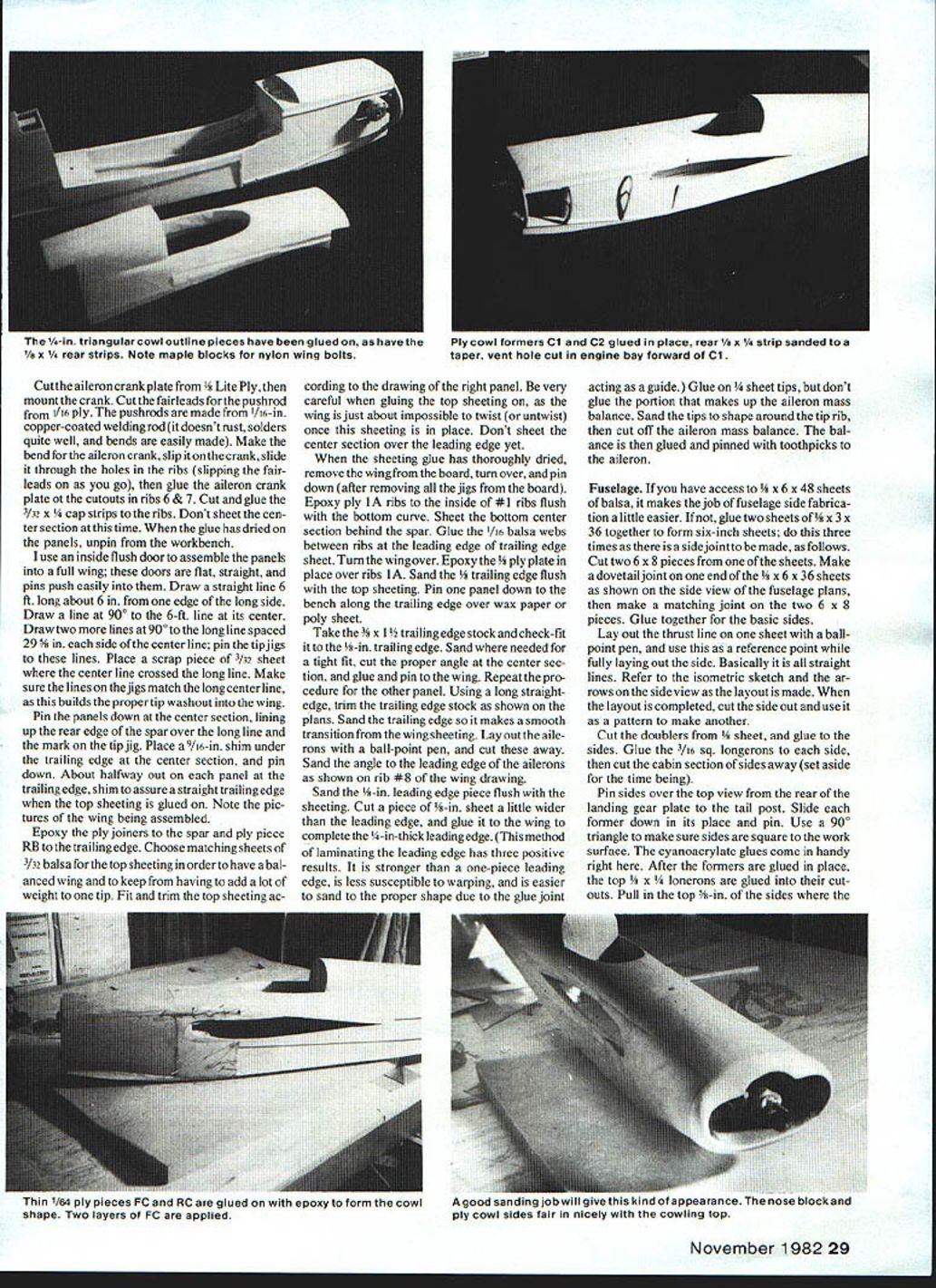
Glue the 1/8 x 3/4 vertical strip to the front edge of BSF. Refer to the side view and measure the cowl outline; mark the fuselage sides where these outlines are. Cut and glue 1/8-in. triangle stock inside these lines, with the wide side glued to the fuselage. Note cross sections of F-2 and F-3. Cut C-1 and C-2 pieces from 1/8 ply and glue in place. Cut the side away from F-1 and C-1 for air venting, and taper the 3/8 x 1/4 strip. Fair the 1/4-in. triangle into the formers. Note the bottom of the cowl on section F-3. Cut four cowl pieces (FC) from 1/64 ply (this section of the cowl is doubled).
Check-fit the cowl by pinning in place over F-1, halfway over C-2, and totally covering the 1/4-in. triangle outline. Trim where necessary for a good, snug fit. Epoxy the fuselage sides inside the cowl to fuel-proof it. Epoxy the inside of cowl FC, put in place, and pin all around. Don't put both C-1s on the engine side yet, as one of them will be glued to the inside of the cowl after it is cut off.
Cut the two RC pieces from 1/64 ply. Check-fit them and trim where needed. Epoxy the inside and glue in place over C-2, the 1/4-in. triangle, and the vertical 1/4 x 1/4. Epoxy the inside of the other FC pieces and put them over the FC pieces already glued to the fuselage. Use rubber bands around the fuselage to help hold them snug to the existing cowl, and pin all around the edges. When the cowl has dried, sand the FC pieces square with F-1.
Rough-cut the 3/8-in. nose block and glue F-1. Using 100-grit paper on a block, carefully sand the top and bottom blocks and the nose to shape, fairing them smoothly to the ply cowl. Take a one-inch block a little larger than the cowl bump and cut one side at an angle (see Step 1 on the fuselage drawing), then cut the outline to rough shape (Step 2). Using 80-grit paper wrapped around a 4-oz. soda bottle or similar cylinder, carefully sand the inside and continue trial-fitting the cowl until a good fit is obtained (Step 3). When a good fit is obtained, cut and sand the outside to rough shape (Step 4), then glue in position as per the side view. Sand the bumps until they fair smoothly into the cowling. Any imperfections in the bumps can be smoothed with putty before covering and finishing. Using a Zona Saw, cut the cowl at the cabin section separation and remove cabin.
Tail surfaces
Cut a 1/4-in. slot in the turtledeck top block where the forward fin goes, using a straightedge to line it up with the fuselage center line. Bolt on the wing and fit the stab in the slot on the turtledeck sides. Line up the stab parallel with the wing in rear view and square with the fuselage in top view. Glue the stab in place, then glue the fin using 90° angles made from scrap balsa to keep the fin square with stab and wing while drying.
The elevator connecting bar is made from 3/16-in. brass tubing and 1/32-in. music wire. Solder the music wire into holes in the tubing. Recess the elevators where the tubing goes. Pin the elevators down to the workbench the proper distance apart and butting against a straightedge. Fit the bar to the elevators and mark the places where the music wire enters the elevator. Drill holes in the elevators, then pin back down making sure they are even. Epoxy the bar in place.
I always cut the slots and fit the hinges to the surfaces before finishing is put on the model (this can be done now). The hinges will be glued in after the model is completely finished.
Detailing
A Williams Bros. 2-1/2-in. sport pilot was used with a few modifications to try to make it look like Leo Loudenslager. The point of the nose was sanded off slightly; talc and dope was mixed to a stiff putty to modify the hair. This mixture will soften the plastic, so be careful (it takes about two days to harden again). I painted the mixture on the head using photos of Leo as a guide. When dry, a coping saw blade was raked across the putty to simulate hair, then I painted the hair with yellow Pactra "Namel", followed by a mixture of flat brown and yellow to lighten the brown. After all this was dry, the saw blade was used again to simulate strands of hair. It takes a little 'fuzzing,' but the results are pretty good. The shirt was painted flat red. When Leo saw the pilot figure in Sherman, he laughed and Jim Roberts said it looked just like him — so I guess it's close enough for Sport Scale.
The inside of the cockpit is sanded smooth. The 3/32 sheet instrument panel is glued in place, and the cockpit is painted. Glue a block of balsa to the bottom of the pilot figure and trim it to the shape of the pilot. Place the pilot in the cockpit and trim the bottom block until the head just clears the cockpit. Paint the block red to match the pilot's shirt, and glue it in. Glue on the canopy, being careful not to smear glue on it. Mask off the canopy to keep it clean while finishing the model.
Mark off the portion of the front cowl that is removable over the engine. Use a Zona Saw with the back removed to cut this portion away. Glue the 1/8 ply hold-down tabs in place. Drill 1/8-in. holes in the cowling for the dowels and glue in the dowels with Hot Stuff. Drill through the dowels and ply tabs, then mount blind nuts under the tabs. Glue the other C-1 inside the cowl flush with the rear edge as shown.
Make the smoker valve as shown on the drawing, or buy a commercial valve. Mount it on plywood and epoxy it to the inside of the cowl as per the top view. A combination smoke chamber, tail pipe, and muffler is fabricated from light steel tubing, 1/8-in. soft brass tubing, and a 12-gauge sheet metal flange. It is stuffed with steel wool and capped with 26-gauge sheet with holes drilled in it.
To have enough heat to vaporize the fluid, insulate the whole chamber with six or seven wrapped thicknesses of fiberglass cloth. Make covers for the insulation from tin can. Bend the sheet metal over the fiberglass and solder the edges, holding in place with twisted wire until the solder hardens. This generates smoke very nicely when using Texaco "Alumag" fluid; the smoke is dense and has good "hang time." Cover the engine mount bolts with short pieces of fuel tubing, and brush slow-drying epoxy all inside the engine compartment to fuel-proof it.
Covering, finishing, and hardware
The model presented here has a doped finish. Silkspan was used on the bottom half of the fuselage and all of the wing. The remainder of the model was covered with lightweight Silkspan. Aerolac metallic blue is very close to the color of Leo's Laser. Yellow trim was used, adding white until the correct shade was attained to match the decals.
The best way I found to match the decal color was to cut out the 7/16-in.-wide LASER 200 decal and attach it to the blue-doped wheel pants in the proper place—then keep experimenting with the yellow until it matched the decal color. A dab of blue may have to be added to the yellow for a really good match.
The star sizes are shown on the fuselage drawing. The fuselage stars were masked off and doped white. A pattern of the wing stars was made from 1/8 ply, and the stars were cut from a Sig white decal sheet. The decals that come with the plans are given two coats of clear polyurethane after they have dried thoroughly.
The tail feather bracing is made from .045 music wire with #26 solder lugs soldered to the ends and held with 2-56 bolts. The simulated rib stitching on the fin, rudder, stab, elevators, and ailerons is made from Manila paper tile folder material; a pizza cutter is rolled over it at about 7/16-in. intervals to indent it, then it is cut into 3/16-in. strips and doped to the surfaces. The effect is good at 15 feet.
Most folks have their own favorite way of installing the radio gear. Mine is shown on the plans. My ship balanced on the CG shown without adding any weight.
If you build this bird, I believe it will give you many hours of truly enjoyable aerobatic flying. If you go the full route with detailing, it will be competitive with other Sport Scale models at the various meets. See you there!
Transcribed from original scans by AI. Minor OCR errors may remain.

