
Model Propeller: Noise
R. Vess, D. Heathcoat, and R. Nagel
This first in a series of articles describes in-depth research, sponsored by AMA and conducted at North Carolina State University, on the severity, sources, and reduction of propeller noise. The findings, some of which are unprecedented, could have a major impact on the model airplane flying community.
Advances in model aviation over the past decade have spurred tremendous growth in the hobby. Each year thousands of people across the U.S. become active participants in weekend sessions at local flying fields. The greatest influx of newcomers naturally occurs near large cities where the population is concentrated, so flying sites tend to be located in suburban areas. While this allows easy access for fliers, it also subjects many uninterested neighbors to the characteristic whine of model aircraft.
Not surprisingly, the greatest activity at the model field occurs on weekends or weekday evenings, which is exactly when people living nearby are at home expecting a chance to relax. Those involved in the sport are well aware of the bitter confrontation that this scenario sometimes provokes. Often the modelers lose the battle and begin a search for another suitable flying site.
Losing an established flying site and having to search for a new one can be frustrating and costly. Ultimately it has a negative effect on the organization and on the continued growth of the sport. Continuously relocating flying fields farther and farther away from populated areas is not the answer. At the rate of rural development, flying site relocation will do little more than postpone the inevitable return of the problem. The solution is to develop model aircraft that operate at lower sound levels.
It is commonly accepted that model aircraft noise is generated by the propulsion system. To the casual observer the most obvious sources are intake, combustion, and exhaust noise generated by the power plant—and the airframe noise resulting from its characteristic vibration. However, the propeller is also an important source of noise—one that is misunderstood and consequently overlooked.
Acoustic research with full-scale aircraft indicates that propeller noise dominates other sources of sound. As stated in the Journal of Aircraft: "It has been well known for years that on propeller-driven aircraft the propeller is a primary source of noise." This observation may hold true for model aircraft as well.
Research program
In an effort to better understand model propeller noise and to establish guidelines that will lead to quieter model aircraft, the AMA sponsored a research program conducted at North Carolina State University. Principal investigators include:
- Dr. Robert T. Nagel — associate professor, nearly 15 years research experience in aeroacoustics.
- Robert Vess — aerospace engineer, six years experience, coordinator NC State University aerospace laboratories, 18 years activity in radio control including pattern, helicopter and fun-fly competition.
- David M. Heathcoat — received a bachelor's degree in physics from NC State University in 1986 and participated in the propeller noise research as a master's thesis.
This first article describes the tests performed, explains the results, and makes recommendations toward reducing model aircraft noise. Improving the noise problem, which means averting the loss of flying sites, will depend largely on having knowledgeable fliers.
Because the material is technical, the discussion of the test program is preceded by a brief explanation of basic propeller theory. Introducing important aspects of propeller performance will lead to a better understanding of both the current study and propellers in general. Every effort has been made to avoid formulas and excessive scientific jargon.
Basic Propeller Theory
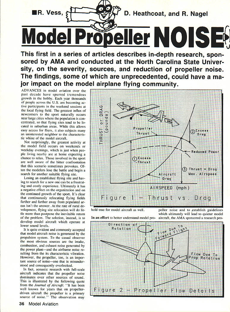
A propeller is essentially a small rotating wing that produces the thrust required to propel an aircraft through the air. The speed of an aircraft in level flight is determined by relating the thrust available from the power plant to the total aircraft drag. Both forces vary significantly with airspeed, as depicted for a typical aircraft in Figure 1.
For example, when moving from left to right along the horizontal axis of Figure 1 (increasing airspeed), aircraft drag increases and eventually exceeds thrust. Point 1 on this figure represents a case in which the aircraft is accelerating, since the thrust produced by the propeller is much greater than the aircraft drag. Conversely, if the aircraft is operating at point 2, drag predominates over thrust and it decelerates. In a given case the airspeed will stabilize at point 3, where thrust and drag are equal.
Since the engine in this example is at full throttle, point 3 represents the maximum attainable airspeed for this aircraft/engine/propeller combination in level flight. A reduction in power below full throttle effectively shifts the thrust curve downward, reducing the maximum airspeed (see the dashed curve in Figure 1). Similarly, anything that produces more thrust or less drag shifts these curves, allowing greater flight speeds.
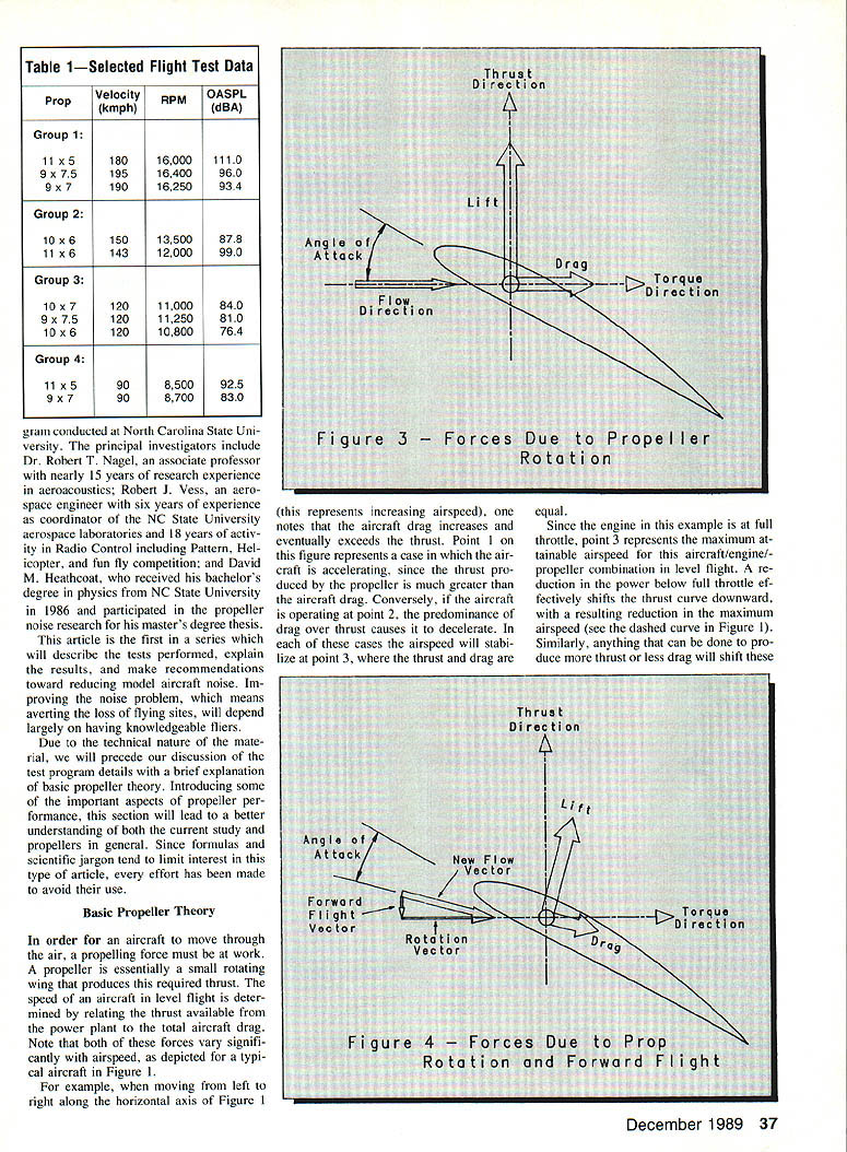
The thrust produced by the power plant actually decreases beyond a certain airspeed. This results from changes in airflow around the propeller at high airspeeds. As a propeller rotates, the flow approaches its leading edge at a speed that depends on the rotational speed (rpm) of the engine. Forward movement of the aircraft creates an additional flow that approaches the propeller disc at a speed equal to the flight velocity. Figure 2 illustrates the relative directions of these simultaneous flows with respect to a propeller rotating counterclockwise.
The forces acting on the propeller are best explained by examining a thin slice of one blade, such as the cross section shown in Figure 2. The explanation is simplified by differentiating the effects due to blade rotation from those caused by forward speed.
Propeller forces and torque example
Consider the forces acting on a blade due to drag and where they act along the blade. Assume the drag forces acting at every point on one blade sum to 1/2 lb, and that this net drag acts through a point 12 in. from the center of the crankshaft. The product of the 1/2 lb and the 12-in distance represents a 6 in.-lb. (or 1/2 ft.-lb.) torque load on that one blade. Since there are two blades, the net torque load the power plant must produce to turn the blades at a constant rotational speed is 12 in.-lb. (1 ft.-lb.). If the engine is capable of producing more torque under these conditions, rotational speed will increase; if it can't produce enough torque, that rotational speed will not be achieved.
Rotation-only flow and forward-flight flow
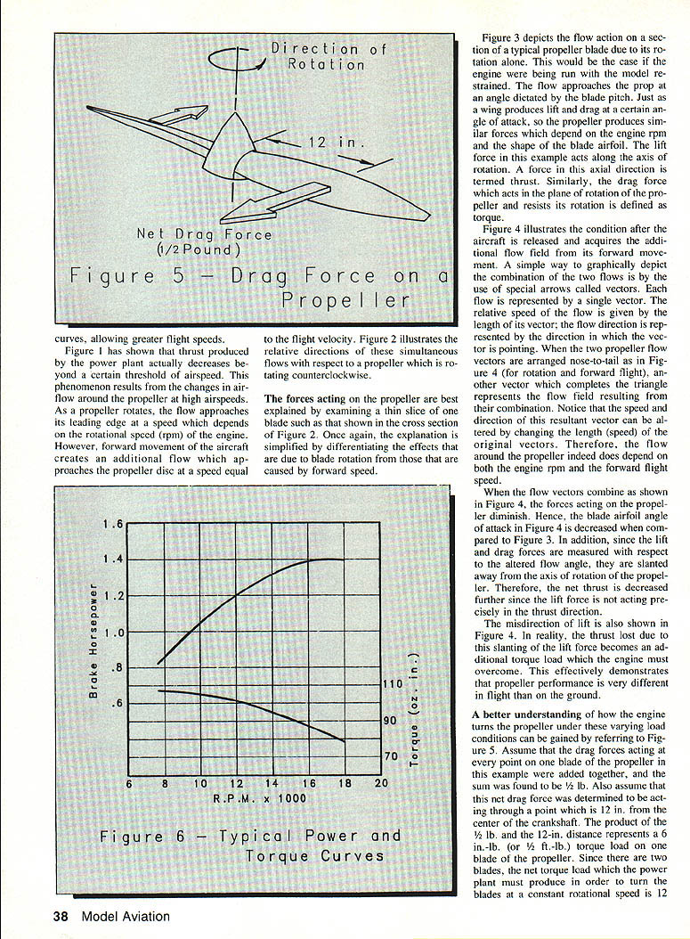
Figure 3 depicts the flow action on a section of a typical propeller blade due to its rotation alone (for example, the engine run with the model restrained). The flow approaches the prop at an angle dictated by the blade pitch. Just as a wing produces lift and drag at a certain angle of attack, the propeller blade produces similar forces depending on engine rpm and blade airfoil shape. The lift force in this example acts along the axis of rotation and is termed thrust. The drag force acts in the plane of rotation and resists rotation; this is defined as torque.
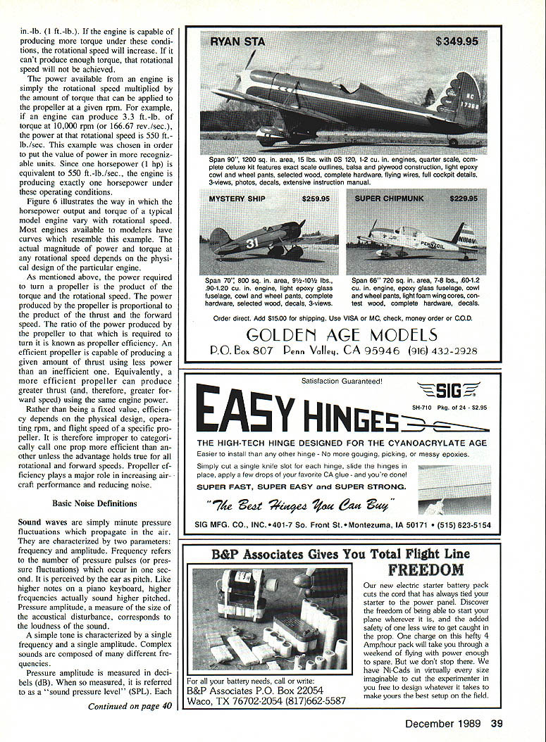
Figure 4 illustrates the condition after the aircraft acquires the additional flow field from its forward movement. A simple graphical method uses vectors: one vector represents the rotational flow and another the forward-flight flow. Arranged nose-to-tail, the third vector that completes the triangle represents the resultant flow field. The speed and direction of this resultant vector depend on engine rpm and forward flight speed, so the flow around the propeller depends on both.
When the flow vectors combine, the angle of attack on the blade is decreased compared to the rotation-only case. Since lift and drag are measured with respect to the altered flow angle, they are slanted away from the propeller axis. Net thrust is decreased further because the lift force is not acting precisely in the thrust direction. The misdirection of lift also becomes an additional torque load the engine must overcome. This demonstrates that propeller performance in flight is very different from on the ground.
The power required to maintain level flight is the product of thrust and forward speed. Because thrust decreases with speed in the region between certain operating points, the power required may actually decrease before increasing again at higher speeds. See standard texts for a more thorough discussion.
Power and efficiency
The power available from an engine is the rotational speed multiplied by the torque applied to the propeller at that rpm. For example, if an engine can produce 3.3 ft.-lb. of torque at 10,000 rpm (about 166.67 rev./sec.), the power at that rotational speed is 550 ft.-lb./sec. Since one horsepower is equivalent to 550 ft.-lb./sec., the engine is producing exactly one horsepower under these conditions.
Figure 6 illustrates how horsepower output and torque of a typical model engine vary with rotational speed. Most model engines have curves that resemble this example; the actual magnitudes depend on the particular engine design.
The power produced by the propeller is proportional to the product of thrust and forward speed. The ratio of power produced by the propeller to the power required to turn it is known as propeller efficiency. An efficient propeller produces a given amount of thrust using less power than an inefficient one. Equivalently, a more efficient propeller can produce greater thrust (and therefore greater forward speed) using the same engine power.
Propeller efficiency is not a fixed value; it depends on physical design, operating rpm, and flight speed. It plays a major role in increasing aircraft performance and reducing noise.
Basic Noise Definitions
Sound waves are minute pressure fluctuations that propagate in the air. They are characterized by two parameters: frequency and amplitude. Frequency refers to the number of pressure pulses that occur in one second and is perceived by the ear as pitch. Higher frequencies sound higher pitched. Pressure amplitude is a measure of the size of the acoustical disturbance and corresponds to loudness.
A simple tone is characterized by a single frequency and amplitude. Complex sounds are composed of many different frequencies.
Pressure amplitude is measured in decibels (dB). When so measured it is referred to as a sound pressure level (SPL). Each SPL corresponds to a discrete frequency or range of frequencies. The overall sound pressure level (OASPL), also measured in decibels, is obtained by adding the SPLs at every frequency in the spectrum. The decibel scale is logarithmic, compressing the wide range of human hearing for ease of interpretation.
Another measure of noise is sound power level (PWL), based on the acoustical power produced by a source rather than the pressure amplitude at a location. Since PWL is also measured in dB, it is important to note whether given values are PWLs or SPLs.
Sounds in certain frequency ranges are perceived as louder than others. Weighted sound level curves have been developed to take this into account. Of these, the A-weighted scale is used for most industrial and community noise standards in the U.S. Sound levels measured on this scale are expressed in dBA.
Understanding how sound levels combine is important:
- When two equal SPLs are added, the combined sound level is 6 dB higher than each original value.
- Adding two equal PWLs produces a level 3 dB higher.
- Because of the logarithmic nature of decibels, levels separated by only a few dB are very different in absolute terms.
When PWLs differ by 10 dB or more, the combined power is only slightly above the higher level. For example, adding 80 dB and 90 dB as powers yields:
dBtotal = 10 log[10^(80/10) + 10^(90/10)] ≈ 90.4 dB
SPLs require about a 20 dB difference before addition becomes insignificant. If one adds SPLs of 80 dB and 100 dB, the result is about 100.8 dB.
Practical implication: model aircraft noise derives from several sources — engine, airframe, and propeller — and propeller noise itself blends several components. Often, reducing a lesser noise source does not produce a noticeably quieter aircraft. For example, an aircraft with 80 dB of engine noise and 90 dB of propeller noise: completely eliminating the engine noise (the lesser source) would only decrease the total by about 0.4 dB, not a significant change. To achieve meaningful noise reduction it is necessary to reduce the dominant source.
Justification of Propeller Noise Reduction
A fundamental objective of this research was to verify that sound produced by the propeller is the dominant noise mechanism in model aviation, assuming a reasonable off-the-shelf muffler is used on all aircraft. Without such muffling, engine sounds are likely to dominate. Measurements from different phases of the research provide evidence indicating that propeller noise dominates over that produced by a properly muffled engine.
Flight test data provides the first evidence. An instrumented aircraft was flown at a fixed height over a microphone while peak OASPL (in dBA), flight speed, rpm, and throttle setting were recorded. This data was compared to that obtained when the same propellers were driven by an electric motor in the wind tunnel laboratory, thereby eliminating the power plant as a significant noise source. Although flight velocities were not precisely duplicated in the lab, several cases offered a reasonable basis for comparison.
In one case, the SPL at the blade-passing frequency in the lab was 78 dB at a simulated flight velocity of 100 km/h. The microphone distance was corrected to the same distance used in flight tests. The flight test at 120 km/h resulted in an OASPL of 76.4 dBA. The OASPL includes all frequencies in the spectrum, whereas the lab data was obtained only at the blade-passing frequency.
Since engine and airframe noise are absent from the lab data, one would have expected the flight test noise to be louder. The results support the inference that engine and airframe noise did not reach significant levels in the flight tests. In fact, the propeller noise alone is approximately equal to the total noise measured in flight.
Table 1 shows selected data in which operating conditions are nearly identical. Group 1 contains propellers from the same manufacturer with total variation from the mean rpm of less than 1% and a total variation in flight velocity of approximately 5%. Groups 2 and 3 each included propellers from two different manufacturers; Group 4 propellers are from a single manufacturer.
Since flight speed and rpm are nearly the same for each group and the aircraft was in level flight at the measurement point, the thrust produced is likewise nearly the same for all data groups in Table 1. The engine and airframe thus behave almost identically in all groups. It can therefore be inferred that the observed large variations in OASPL between cases within each group result from differences in sound levels among propellers. Further, assuming engine noise closely approximated the level of propeller noise, completely eliminating the engine noise would effect a reduction of only 6 dB—less than the differences noted among props in a particular group.
A final piece of evidence came from tests using two different mufflers during flight. A stock muffler was replaced by a high-quality, state-of-the-art muffler; data were recorded at two flight speeds using the same propeller. At 120 km/h, the difference in OASPL was only 0.2 dBA. At 90 km/h, the difference was 0.3 dBA. Such extremely small variance suggests the advanced muffler had no effect on total noise output at a given flight speed. While the advanced muffler improved engine performance (allowing additional rpm), this increased rpm raised noise levels. Thus, although it improved engine performance, the advanced muffler did not significantly impact noise level as long as flight speed remained constant.
These test results clearly establish the propeller as the dominant source of model aircraft noise. The remainder of the research assumes this to be the case.
Propeller Noise Sources
Propeller sound is compounded of several elements, the most important of which include thrust noise, torque noise, and thickness noise. These are referred to as discrete frequency noise sources because the sound produced by each occurs at the blade-passing frequency and its harmonics. The blade-passing frequency is the rate at which a blade passes any given point in the propeller disc; it equals the product of the number of blades and the rotational speed (rev./sec.).
To understand these mechanisms, imagine a fixed point in the propeller disc. When a blade is not near this point, the air pressure is at its ordinary value. As a blade passes, it pushes air aside; the amount of displaced air depends on blade thickness. The noise produced by this periodic displacement of air is thickness noise.
As the blade passes, it also exerts thrust and torque forces that cause pressure fluctuations. These fluctuations propagate as sound, known as thrust and torque noise. At every point in the propeller disc, the pressure fluctuates each time a blade passes.
The total pressure disturbance is the sum of disturbances caused by thrust, torque, thickness, and other effects. These disturbances vary in strength and each tends to radiate in preferred directions. The combined effect is perceived as propeller noise.
The pressure amplitudes of each component depend on the relative amounts of thrust and torque, and on propeller tip speed (proportional to rotational speed times propeller diameter). Thrust and torque noise are generally the most significant sources of propeller sound. Thickness noise is considerably more affected by tip speed than thrust and torque noise; thus its relative importance increases with increasing rotational speed.
Any attempt to make sense of propeller noise is complicated by overlapping and interdependent effects of the acoustic sources. For example, the blade lift does not point exactly in the thrust direction; this means blade lift contributes to both thrust and torque, and hence to both thrust and torque noise. Additionally, noise from various sources radiates away from the propeller in overlapping patterns that are difficult to distinguish.
To reduce propeller noise, one must discover the dominant noise mechanism so that work can be directed toward lessening that source. That requires knowledge of the intricate makeup of propeller noise and the interplay of all factors associated with aircraft operation—engine performance, aircraft drag, flight speed, rpm, propeller diameter, pitch, etc.—which together produce the noise perceived by the human ear.
A structured building-block approach is being used at North Carolina State University in which laboratory data is correlated with flight test data and classical mathematical propeller theory. Although time-consuming, this approach provides a direct path to useful answers.
The research findings suggest that propeller noise may be the dominant acoustic source in model aircraft and that it may be possible to diminish this leading cause of poor community relations. Much of the cure will depend upon education. Modelers need to understand the nature of the problem in order to properly utilize solutions.
This article has introduced the propeller noise problem and provided background. Subsequent articles will explain the test results in greater detail and describe what the modeler can do to achieve better aircraft performance with less noise.
Transcribed from original scans by AI. Minor OCR errors may remain.

