
Model Propeller Noise
By R. Vess, D. Heathcoat, and R. Nagel
In the three preceding articles of this four-part series reporting an exhaustive propeller-noise study conducted at North Carolina State University and sponsored by the AMA, the authors demonstrated that the average commercial propeller is inefficient and is the major source of model-airplane noise when the engine is properly muffled. This concluding segment discusses what can be done to solve the problem.
THE PREVIOUS articles have shown that propellers are the main source of model-aircraft noise, explained the various sources of propeller noise, and demonstrated that noise due to torque loading is the dominant source. Last month’s article concluded with these points:
- The propellers available are generally very inefficient; this inefficiency leads to high torque loads relative to the thrust produced.
- The path to model-aircraft noise reduction is therefore clear (although perhaps not easy): make propellers more efficient to reduce noise without compromising aircraft performance.
- Too much of the engine’s work is spent turning the propeller and not enough is used pulling the aircraft through the air.
Thought experiment: If a model’s propeller were replaced by a circular rod, the model would not fly. The motor would work, the rod would spin, a great deal of noise would be generated, but no thrust would be produced. The rod would be a terrible propeller. The noise from the “rod propeller” would be due to thickness and torque. If the rod and the propeller were sized so the engine turned them at the same rpm at full throttle, the engine would be doing the same amount of work in each case—and it may be surprising that a rod and a propeller produce similar noise levels under similar conditions. However, the rod’s noise has nothing to do with thrust. Unfortunately, many model propellers are a little too much like the rod: they generate a large amount of torque noise for a given amount of thrust.
Responsibility and approach: The responsibility for model-aircraft noise lies with fliers and manufacturers. A combination of education for modelers, conscientious flying-field practices, and state-of-the-art equipment will be required to reach a workable solution. The information in this series is intended to provide part of that education.
What to avoid and practical flying considerations
- Model aircraft flown at high speeds far down the runway—closer to distant houses—are likely to annoy nearby residents.
- Typical flight noise at the runway tends to be short in duration, but noise associated with preparation, takeoff, landing, and taxiing may reach neighbors for longer periods.
- Therefore, strict noise-control efforts should be directed toward high-speed flight conditions (the most important case).
- Flying in flight differs greatly from a restrained (static) craft in both propeller performance and radiated noise because the flow fields around the propeller change with forward motion. Thus, the common practice of measuring noise of an aircraft held at rest on the ground addresses the wrong condition.
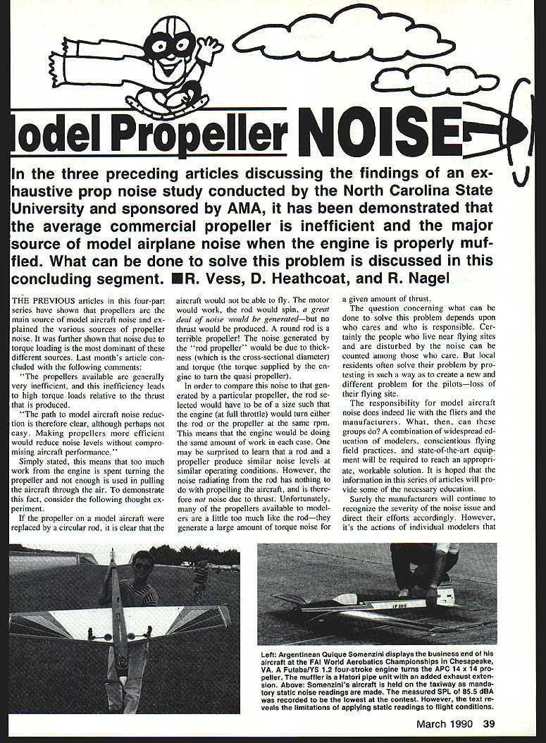
Case study: The 1989 F3A World Aerobatics Championships (Chesapeake, VA) illustrates this. In FAI competition the SPL measured at 3 m from the sideline must not exceed 98 dB. Although aircraft met this requirement, many were very quiet in flight—much quieter than static readings suggested. High-pitch propellers (e.g., the APC 14×14 used by Quique Somenzini) perform well and significantly decrease overall noise in flight. High-pitch props reach peak efficiency at higher flight speeds and therefore generate less noise at those speeds. When the model is restrained on the ground, excessive angle of attack promotes flow separation and produces a static acoustic signature not representative of in-flight operation.
This demonstrates the need to measure noise in flight—when it is perceived by people on the ground.
Flight measurements and data limitations
Measuring noise in flight introduces logistical problems. It is possible, however, to develop a method to predict in-flight noise from experimental data acquired under controlled conditions. The in-flight measurements could be made by qualified individuals with proper equipment, and the resulting data used to create a noise-prediction method for everyday modelers. The same data can predict aircraft performance and enable propeller selection that addresses both performance and noise.
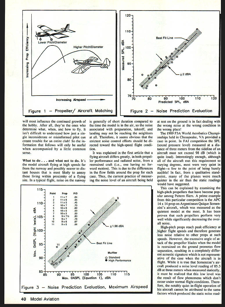
Until recently, most modelers simply picked one of the two or three props listed by the engine manufacturer. This is a poor method. Proper choice depends on the specific aircraft/engine combination at the desired flight condition. For example, a trainer (low airspeeds) needs a prop efficient and quiet at slow speeds, while a high-performance sport aircraft benefits from props that reach peak efficiency at higher airspeeds (higher pitch-to-diameter ratio). With fixed-pitch props, the range of high efficiency is limited, so choose a prop whose peak efficiency occurs near the aircraft’s typical airspeed.
To reduce the number of variables, aircraft can be grouped by aerodynamic characteristics (trainers, sport, high-performance). Data from flight tests of representative aircraft can be used to derive prediction methods for other aircraft in that group. The research used the “Miss Martha” aircraft as an example of an advanced sport aircraft; the resulting prediction methods apply to similar sport aircraft.
Data limitations encountered in the Miss Martha flight tests:
- Proper engine needle-valve setting was difficult to maintain throughout the runs; inconsistencies in available power introduced inconsistencies in performance and acoustic data.
- Several microphone-position changes were made during the tests because suitable locations were difficult to find; this likely introduced additional inconsistencies in recorded sound-pressure levels.
- The simplicity of the airborne telemetry limited the achievable accuracy of performance data recorded on the ground.
- Varying wind conditions and different aircraft test speeds made it difficult to consistently fly directly over the sound-level meter; flyover distances were judged by sight and subject to human error. Data were only recorded after three repeated “good” passes over the microphone.
These limitations do not discredit the data but qualify its accuracy. Many conclusions from lab experiments were favorably supported by the flight-test data despite measurement error.
Noise prediction
Correlation of acoustic flight data with geometric parameters measured from propellers provided the foundation for a noise-prediction method. Parameters were weighted in a single equation, the fit evaluated, and the process repeated until error was minimized. The complex result of that effort (rearranged for clarity) is:
OASPL_pred = (110 log D) - (15 log P) + (40 log N) + (110 log σ) + [175 log (1 + J/Pt)] + [(1 + 3M_t + J) · 32 log {((D - 9)^3 + 15)/15}] - 64.29
Variables:
- D = prop diameter, inches
- P = pitch, inches
- N = rotational speed, rpm
- σ = solidity of the outer half of the propeller
- J = advance ratio
- M_t = prop tip Mach number
Plotting predicted OASPL against measured OASPL produced a best-fit line slope of 0.97, indicating the prediction represents the available data well. Data scatter (mean ≈ 2 dBA) is primarily due to experimental measurement error and compares favorably with noise-prediction equations in the aerospace industry.
This equation predicts propeller noise only when each variable is known, which limits its practical use since few modelers can measure airspeed or engine rpm in flight. Clubs need something simpler — a method that uses easily measured parameters.
A simplified equation applicable to maximum flight speed (the speed of most interest) was developed. It is based entirely on propeller geometry so a ruler and pocket calculator are the only tools required:
(1) Max OASPL = 20 log [ (D/4) × (P/D)^-1.1 × (C_.75R/R)^0.75 × R^0.16 × PH ] + 255.04
Input variables for Equation (1):
- D = propeller diameter, inches
- P/D = pitch-to-diameter ratio
- C_.75R/R = propeller blade chord at 0.75R divided by radius (for example, C_.50R means chord at 0.50R)
- R = propeller radius (half diameter), inches
- PH = power parameter: PH = 1.0 for standard/stock mufflers; PH = 1.05 for high-performance mufflers
PH adjusts for exhaust-system effects: high-performance mufflers tend to increase maximum flight speed (and noise at that speed), but when tested at the same attainable flight speeds the noise remains roughly unchanged.
A comparison of predictions from Equation (1) with measured Miss Martha data at full throttle showed propeller noise ranged from about 87 dBA to over 110 dBA. Propeller selection made the difference between a quiet aircraft and an extremely noisy one. Despite measurement error, general trends show props with higher pitch-to-diameter ratios produce less noise in flight. Increased noise with high-performance mufflers is due to the engine performing better (higher speed).
Performance prediction
Using the same approach on performance data yielded an equation to predict maximum flight speed for sport aircraft similar to Miss Martha. Variables are the same as in Equation (1).
(2) Vmax_predicted = 3981 × D^0.1 × (P/D)^0.15 × (C_.75R/R)^1.9 × (C_.50R/C_.75R)^1.65 × (C_.90R/C_.75R)^0.35 × PH^1.1
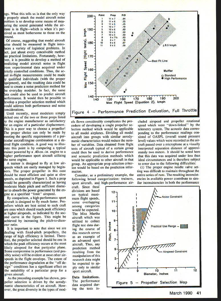
Comparison of measured and predicted flight velocity showed an error of approximately 5% of mean flight velocity (~8.5 km/h). The general trend: props with higher pitch-to-diameter ratios produced higher maximum flight speed and lower noise.
Propeller selection method
By using Equations (1) and (2), a practical method for selecting a propeller that satisfies noise and performance constraints can be developed for sport aircraft. Example:
Aircraft: Miss Martha (advanced sport) Engine: O.S. Max .46 SF Muffler: Davis Diesel Soundmaster (high performance) → PH = 1.05 Desired maximum flight speed: 175 km/h (109 mph) Flying-site noise regulation: 88.0 dBA @ 2 m flyover (≈ 85.3 dBA @ 3 m)
Measured average blade-chord distributions from the propeller database:
- C_.75R/R = 0.177
- C_.50R/C_.75R = 1.07
- C_.90R/C_.75R = 0.725
Substituting known values into Equations (1) and (2) yields pitch–diameter inequalities in inches:
(1a) P ≥ (5.5 × 10^-5) × D^3.6 — Noise constraint (2a) P ≥ 2.95 × D^0.333 — Speed constraint
Plotting these produces a finite boundary above which P/D combinations satisfy the constraints. For this example, the minimum diameter is about 9 inches. Pitch-to-diameter ratios between ≈ 0.55 and 0.8 provide good combinations that meet both constraints (results vary with aircraft and engine).
Functional considerations: props must absorb available engine power at reasonable rpm and perform adequately in off-design situations. This rules out too-small diameters or too-high pitches. When flight testing was performed, the highest P/D prop available for this engine type was 9×7.5 (P/D = 0.83), which theoretically satisfied constraints but did not meet the noise constraint in the imperfect experimental data—likely due to assumptions about average blade-chord distribution and measurement error. The important recognition is that a prop with P/D ≥ 0.83 (or higher) would be required to meet selection criteria; increasing P/D further might achieve the required airspeed with less noise.
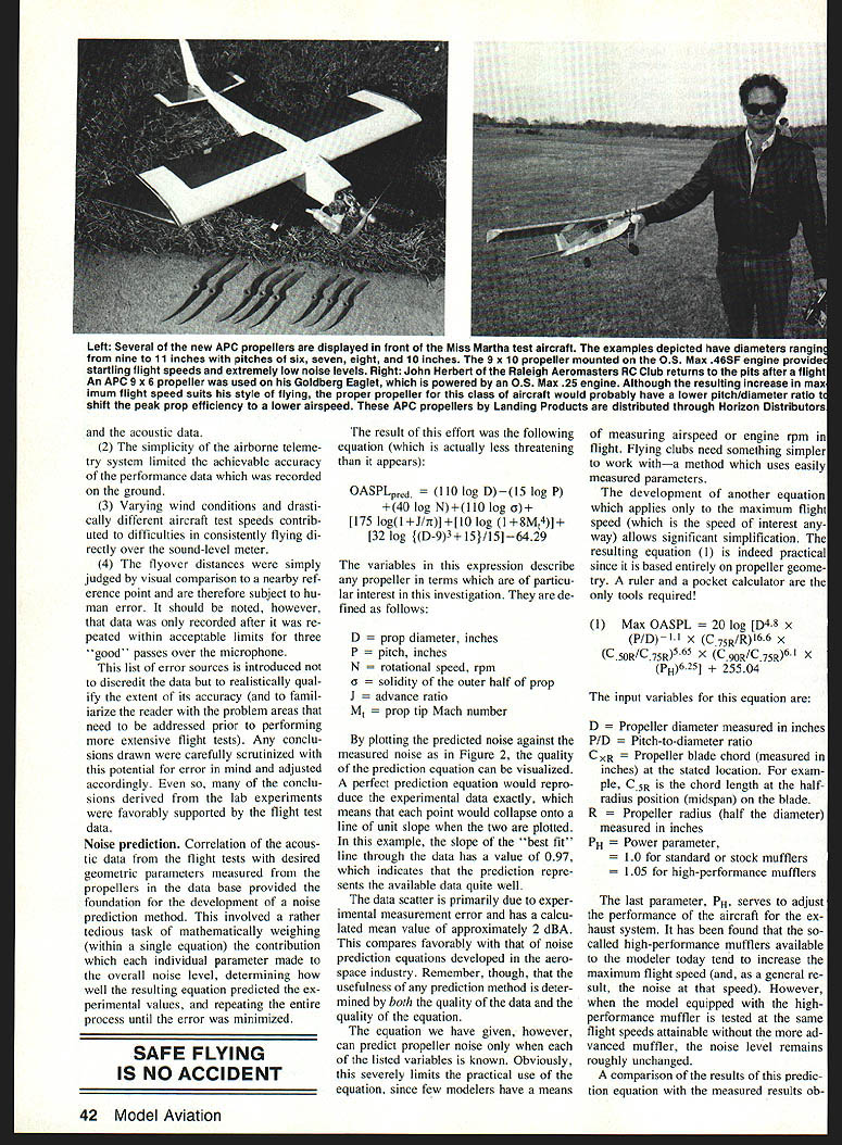
APC props: The introduction of APC (Advanced Precision Composite) props provided further evidence. APC props flown qualitatively on Miss Martha produced excellent results. The APC 9×10 (P/D = 1.11) produced level-flight speeds previously unattained on this aircraft and was notably quiet—the airflow around the plane was audible. Although no instrumentation data were acquired for these props in this study, observations indicate increased efficiency (higher performance and lower noise).
Trade-offs and operational notes:
- Static rpm will be much lower for higher-pitch props due to flow separation on blades when restrained; this is expected. If the prop is “screaming” on the ground, the engine is not sufficiently loaded—flight performance will be compromised and noise increased.
- Takeoff acceleration will be reduced for higher-pitch props, slightly increasing takeoff length; however, most model airplanes have excessive thrust-to-weight ratios, so this is not usually critical.
- Thrust at low flight speeds is reduced, degrading maneuvering performance; climb rate at high speed is excellent. The noise increases when the model slows and power is increased.
As a compromise for the test aircraft, an APC 10×8 was selected as the best balance: maximum flight speed and noise similar to the 9×10, with improved low-speed thrust.
Conclusions
This AMA-sponsored research program aimed to better understand propeller noise, determine the propeller’s contribution to overall aircraft noise, isolate the main source of propeller noise, and establish guidelines to achieve quieter model-aircraft operation. The combination of propeller theory with wind-tunnel and flight-test data led to these conclusions:
- Provided a reasonable muffler is used, the propeller is the dominant noise source for a model aircraft.
- The dominant source of propeller noise is torque noise. More efficient propellers generate more thrust for a given torque, and therefore result in less noise at a given airspeed.
- Propellers currently available to modelers are, in general, quite inefficient. Their use leads to less-than-ideal performance and acoustic characteristics.
- Modelers should select propellers whose peak efficiency occurs near the airspeeds at which the aircraft will usually be operated. In general, props with increased pitch-to-diameter ratios should be made available to match a wider variety of aircraft.
- Noise-reduction efforts should target the maximum flight-speed condition. The only way to truly quantify and reduce perceived noise is to measure it in flight.
- It is possible to develop a propeller-selection method based on in-flight experimental data that addresses both noise and performance, giving average modelers a practical means to meet noise regulations while maintaining satisfactory performance.
- This information will be useful only if applied universally. Organized groups (AMA), clubs, hobby dealers, and manufacturers must educate individuals and enforce proper procedures.
The study disclosed the nature and scale of the propeller-noise problem and introduced practical solutions. Using more efficient propellers will reduce model-aircraft noise. Continued research should study the effect of propeller geometry on overall efficiency to develop optimal blade designs and minimize propeller noise. A carefully organized flight-test program would provide the database needed to develop a standardized propeller-selection criterion.
Transcribed from original scans by AI. Minor OCR errors may remain.

