
Modeling the Ligeti Stratos
Background
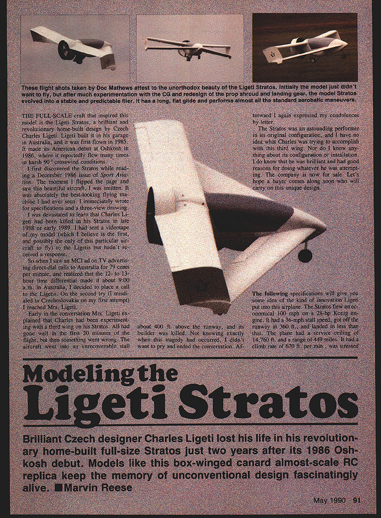
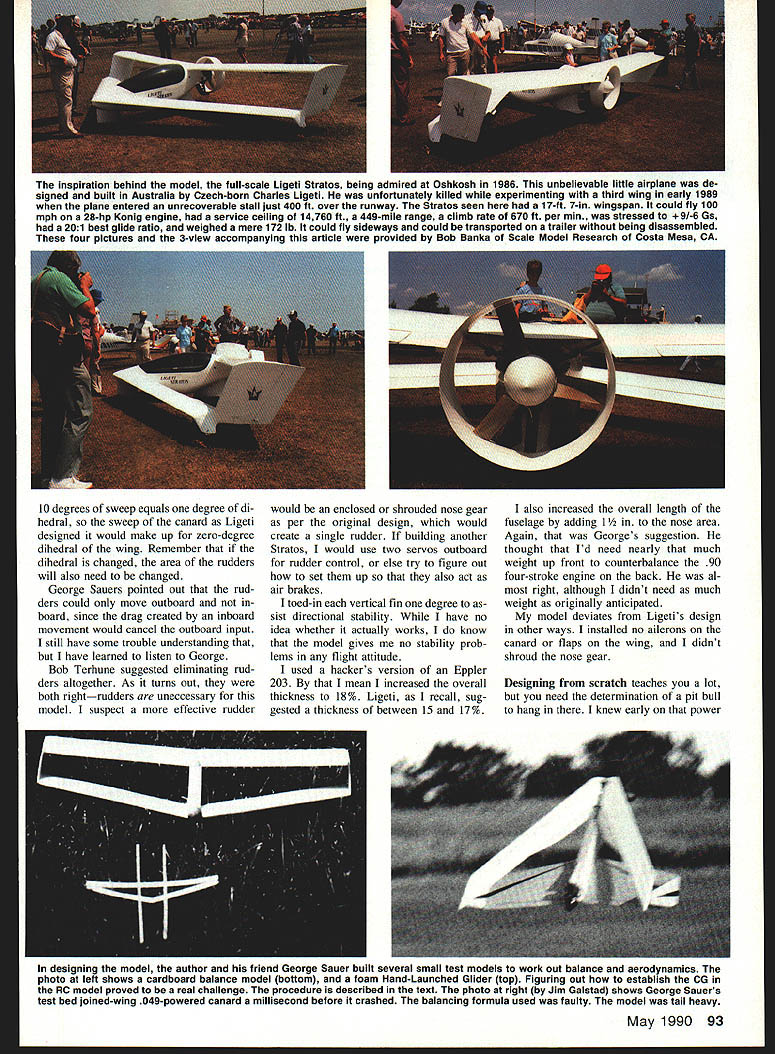
The full-scale craft that inspired this model is the Ligeti Stratos, a brilliant and revolutionary home-built design by Czech-born Charles Ligeti. Ligeti built it in his garage in Australia; it first flew in 1985 and made its American debut at Oshkosh in 1986, where it reportedly flew many times in harsh crosswind conditions.
I first discovered the Stratos in a December 1986 issue of Sport Aviation. The moment I flipped the page and saw this beautiful airplane, I was smitten. I immediately wrote for specifications and a three-view drawing. I later learned Charles Ligeti had been killed in his Stratos in late 1988 or early 1989. I sent a videotape of my model to the Ligetis but did not receive a response. Eventually I reached Mrs. Ligeti by phone; she explained that Charles had been experimenting with a third wing on his Stratos, and during one flight the aircraft went into an unrecoverable stall about 400 ft above the runway.
The Stratos in its original configuration was an astounding performer. It flew an economical 40 mpg on a 28-hp König engine, had a 36-mph stall speed, got off the runway in 360 ft and landed in less, had a service ceiling of 14,760 ft, a range of 449 miles, a climb rate of 670 ft/min, a best glide ratio of 20:1, and weighed a mere 172 lb. It could fly sideways and could be transported in a trailer by dismantling.
Brilliant Czech designer Charles Ligeti lost his life in his revolutionary home-built full-size Stratos just two years after its 1986 Oshkosh debut. Models like this box-winged canard almost-scale RC replica keep the memory of unconventional design fascinatingly alive. — Marvin Reese
Correspondence and source material
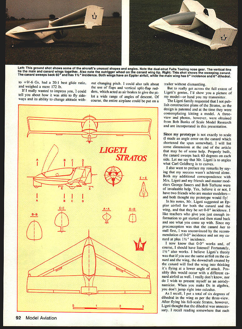
The Ligeti family requested that construction plans not be published because the design is patented and they were contemplating kitting a model. A three-view and photos were obtained from Bob Banka of Scale Model Research and are incorporated into this presentation.
My prototype is not exactly to scale (I made an angle error on the canard that shortened the span somewhat). I will list dimensions at the end of the article that may help. Properly built, the canard sweeps back 60° on each side. Ligeti was meticulous about angles.
I also want to acknowledge help from Mrs. Ligeti, and from friends and master modelers George Sauers and Bob Terhune — both invaluable resources during development.
Design and building
Aerodynamics: airfoil and incidence
Ligeti suggested an Eppler airfoil for both the canard and the wing and recommended 0–0° incidence (both set at 0°). My preconception was that the canard should stall first, so I initially set my canard at +1½° incidence. I later learned that the 0–0° recommendation works fine, and 1½° also works.
Ligeti’s theory was that using the same airfoil on the canard and wing causes the canard’s downwash to make the wing “think” it is at a lower angle of attack, keeping the canard the stalling surface. I’m not an aerodynamicist, but this approach proved effective in practice.
For the model I used a Hacker version of the Eppler 203 airfoil, increasing overall thickness to about 18% (Ligeti suggested 15–17%). I also increased the overall fuselage length by about 1½ in. to add nose area and help balance the heavier rear-mounted .90 four-stroke engine.
Dihedral, sweep and control surfaces
I initially put a total of 6° dihedral in the wing per the three-view. After flying the full-scale Stratos, Ligeti thought dihedral was unnecessary. I recall reading that each 10° of sweep equals roughly 1° of dihedral; with Ligeti’s wing sweep, the dihedral effect could be reduced or eliminated. Changing dihedral also changes the effective area and behavior of the vertical fins/rudders.
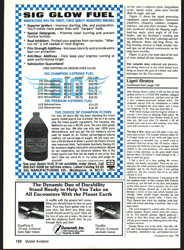
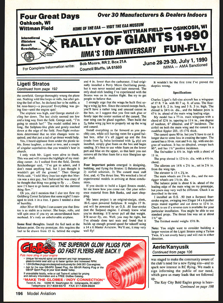
George Sauers pointed out rudders could be used primarily outboard since inboard movement would create drag that cancels outboard input. Bob Terhune suggested eliminating the rudders altogether. In the finished model, right and left rudders proved unnecessary. A more effective single rudder might be an enclosed, shrouded nose gear as on the original full-scale design. If building another Stratos, consider two servos for outboard rudder control or a different set-up to allow the fins to act as air brakes.
I toed in each vertical fin 1° to assist directional stability. The model gives no stability problems in any flight attitude.
My model deviates from Ligeti’s design in other ways: I installed no ailerons on the canard, no flaps on the wing, and I did not shroud the nose gear.
Shroud and propulsion
Power selection was critical. I dislike two-stroke power plants, so I chose a four-stroke despite the prop-diameter constraints imposed by the shroud. Four-stroke engines often want large props, but the shroud limits diameter.
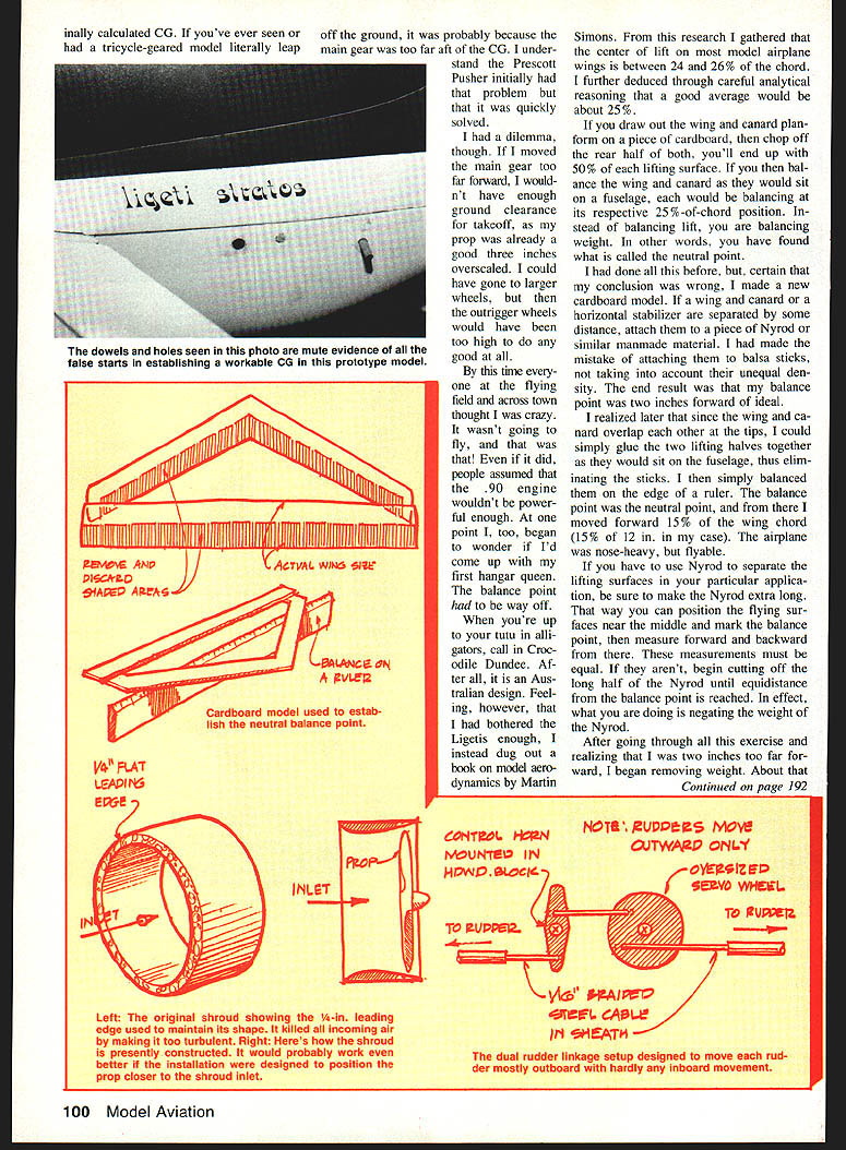
My original all-up weight estimate was 13–15 lb. The prototype came out at 15½ lb — about a 20-oz wing loading. I initially planned to join two 12x6 pusher props turning about 8,000 rpm. In practice I obtained about 8,500 rpm from two 14x6 props cut down to 12½ in. Propeller installation mistakes (props installed backwards) delayed progress until Bob Routh pointed it out.
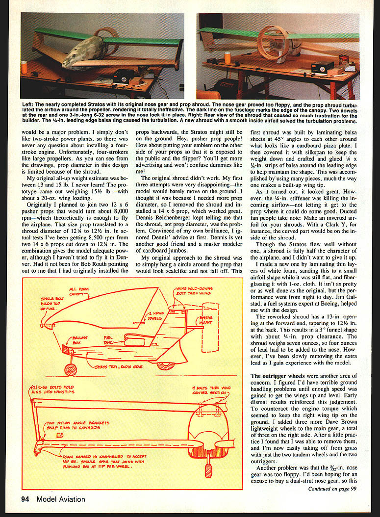
The original shroud design was ineffective — the model would barely move on the ground. My first shroud used laminated balsa with 1/4-in. stiffeners; this choked the inner airflow. Ducted-fan builders take note: make an inverted-airfoil shroud (curved surface inside) rather than stiffening the inner lip.
I rebuilt the shroud by laminating thin layers of white foam, sanding to a small airfoil cross-section (still flat internally), and glassing with 1-oz cloth. Jim Galstad (a fuel-systems expert at Boeing) helped with the design. The reworked shroud has a 13-in. opening at the forward end, tapering to 12½ in. at the back — a 3° funnel shape with about 1/4-in. prop clearance. The shroud weighed 7 oz, so about 4 oz of lead was added to the nose; that has been reduced as experience allowed.
Landing gear, balance and ground handling
Outrigger wheels initially caused ground-handling worries. To counteract engine torque that kept the right wingtip on the ground, I temporarily added three Dave Brown lightweight wheels to the main gear (three on the right side). After practice I removed them and now take off from grass with just the two tandem main wheels and two outriggers.
The 3/32-in. nose gear proved too floppy. I installed a dual-strut nose gear (Fults Tooling RF 500 gear), which has worked flawlessly. I use an old Fox 3 1/3-in. aluminum-hub wheel on the nose gear.
Determining the balance point was a major challenge. We experimented by flying variants and crashing several test airframes. I eventually measured how much weight rested on the nose wheel (initially seven pounds — nearly half the airplane). The problem was the main gear and axle placement: the main gear had been too far aft, so the axle was just about even with the wing leading edge. Moving the main gear forward had to be balanced against prop clearance and outrigger geometry.
To resolve the neutral point and true center of lift, I used Martin Simons’ work: the center of lift on most model wings is about 24–26% of chord, so 25% is a good average. By drawing the wing and canard planforms and balancing them as they would sit on the fuselage (or by constructing a cardboard model and balancing), I found the neutral point. From that point I moved forward about 15% of the wing chord to arrive at a stable balance point. Using Nyrod to separate lifting surfaces requires making it extra long so it can be trimmed to negate Nyrod weight in balance calculations.
Later George Sauers used a CAD/CAM machine to compute a balance point; it agreed with my calculations within 1/4 in. After wheel changes and removing the original shroud, the nose-wheel weight came down to about 3½ lb — much better.
Flight and testing
On the day of the maiden flight, weather and field conditions were changing, but I was determined. After mowing grass to create a takeoff run and a brief run-up, I taxied and then launched. George Sauers was at the sticks. Just after lift-off one wing dropped; he corrected it and headed out over the cornfield. He thoroughly assessed the model — nothing wild, but declared it stable and a bit nose-heavy. Then the engine quit. George stretched the glide and made a long, flat, sailplane-like landing at the edge of the field. Post-flight evaluation showed no trim changes were needed, though a tad of upthrust would help.
After 30–40 flights the Stratos proved as stable as a trainer: it loops, rolls, and will spin once if deliberately uncoordinated. It’s a remarkable airplane.
Building advice and final thoughts
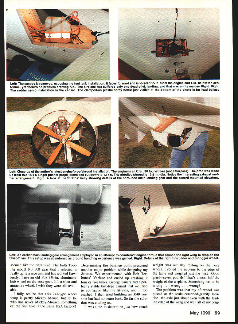
- Install the fuel tank at the balance point. On my prototype that required the fuel to be drawn from 10.5 in. behind the engine and 4 in. lower than the carburetor. I originally installed a Perry Micro Oscillating pump but later removed it.
- Build the wings first using a wing jig box. Because the canard sweeps back, expect a long, unusual cutout in the jig; tack-glue or firmly tape the center section of the canard first. Glue the rear wing together, then build the 3/32-in. balsa wing jig box to properly set up the wing and canard.
- Install everything as far forward as possible while leaving room for a ballast box.
- After everything is jigged up and the fins (3/32-in. balsa laminated with 1/8-in. ply) are installed, glue foam onto the box and begin sanding. Use white foam on the lower part and blue on the upper so you can remove the blue foam later for a nice fiberglass upper shell.
Four important points emerged in designing, building, and flying the Stratos:
- Balance point
- Aileron selection
- The canard must stall first
- The thrust line
We wrecked many experimental models to arrive at those conclusions.
If you decide to build a Ligeti Stratos model, get reference material from Bob Banka and consider the new kit when available. My latest project after the Stratos is an original-design 18-ft-span powered sailplane weighing 17 lb and powered by an O.S. .61 four-stroke; taxi tests look promising.
Specifications
Full-size Charles Ligeti Stratos (as reported)
- Wingspan: 17 ft. 7 in.
- Area: 80.7 sq. ft.
- Fuselage length: 8 ft. 2 in.
- Height: 3 ft. 3 in.
- Shroud diameter: 24½ in.
- Balance point: about 47% ahead of the main wing leading edge
My model (prototype)
- Main wingspan: 77 in.
- Chord: 12¼ in. root, tapering to 11¼ in.
- Washout: 1° (one degree)
- Dihedral: 6° (as built)
- Incidence: 0°
- Root airfoil (main wing and canard): Eppler 203, 15.17% thick (Hacker version used at ~18% thickness)
- Canard span: 90 in. (you may need to cut it longer to allow for taper loss)
- Canard: no dihedral, sweeps back 60°, 1½° positive incidence; 10° nose-up at the tip over an 18-in. tip length
- Fin/rudder: 6½ in. high, 11 in. chord
- Prop shroud: 12½-in. diameter with a 4½-in. rim (reworked shroud: 13 in. forward opening, tapering to 12½ in.)
- Ailerons: 14% chord x 2½ in., set 2¼ in. from the wingtips
- Elevator: 1½ x 2½ in.
- Engine: O.S. .90 (not a Surpass) four-stroke
- Propellers: two Zinger 14 x 6 pusher props (used; often cut down to 12½ in.)
- Thrust line: about 6 in. ahead of the leading edge of the main wing on my prototype (verify on your build)
- Finished model weight: 15½ lb.
Note: Consider building a larger version using a Titan twin — it’s not overly heavy and can run in either direction.
Transcribed from original scans by AI. Minor OCR errors may remain.

