
The Modern Windsock
By Joe Beshar
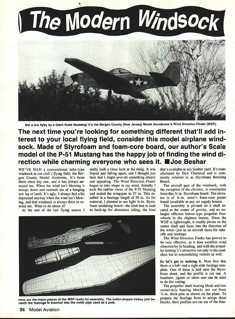
The next time you're looking for something different to add interest to your local flying field, consider this model-airplane windsock. Made of Styrofoam and foam-core board, the author's scale model of the P-51 Mustang has the happy job of finding the wind direction while charming everyone who sees it.
We've had a conventional tube-type windsock at our club's flying field, the Bergen County Model Airdrome. It's been there since day one, and it has always annoyed me. When the wind isn't blowing it droops and reminds me of a hanging wet leg of lamb. It's ugly. I always feel a bit depressed anyway when the wind isn't blowing, and that windsock is always there to remind me. What to do about it?
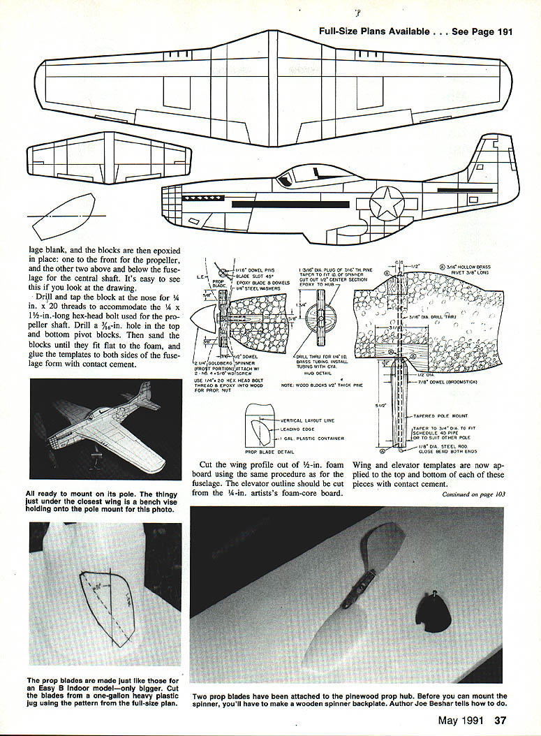
At the end of the last flying season I really took a close look at the thing. It was frayed and falling apart, and I thought then that I might provide something cheery and appealing. The Wind Direction Finder (WDF) began to take shape in my mind. Initially I took the outline views of the P-51 Mustang and scaled the wingspan to 37 in. This resulted in a fuselage length of 30 in.
As for material, I planned to use light 1/2‑in. Styrofoam insulating board — the kind used as back-up for aluminum siding and available at any lumber yard. It's manufactured by Dow Chemical and is commonly referred to as Styrofoam Residing Board.
The aircraft part of the windsock, with the exception of the elevator, is constructed from this 1/2‑in. Styrofoam board. The elevator is of 1/4‑in. artist's foam‑core poster board (available at any art supply house). The assembly is pivoted on a shaft located at the center of gravity, and an enlarged, efficient indoor‑type propeller freewheels in the slightest breeze. Since the WDF is lightweight, it readily pivots on the center shaft and faces into the direction of the wind — just as an aircraft faces for takeoffs and landings.
The Wind Direction Finder has proven very effective: it establishes wind direction by its heading, and with the propeller turning it's attractive not only to modelers but to non‑modeling visitors as well.
Materials (high level)
- 1/2‑in. Styrofoam insulating board (fuselage, wings)
- 1/4‑in. artist's foam‑core poster board (elevator)
- 1/2‑in. and 7/16‑in. pine for bearing blocks and spinner backplate
- Hardwood dowels (various diameters)
- Brass tubing (1/4‑in. ID, short length for prop bushing)
- Goldberg plastic spinner (front end) or similar
- One‑gallon plastic container (sidewall material for prop blades)
- 1/4‑in. hex head bolt with 1/4‑20 threads (propeller shaft)
- Steel flat washers (3) for thrust bearings
- 1/4‑in. steel rod for central pivot (bent at ends)
- Hollow brass rivets (3/16‑in. diameter, 3/8‑in. long) for bearings
- Epoxy, Cyanoacrylate (CA) glue, contact cement, Hobby Poxy #2 (sealer/clear)
- Aluminum spray paint (light mist), clear Hobby Poxy topcoat
- Tools: bandsaw/jigsaw/sabre saw, drill/tap set, sanding tools, files, old soft brush
Overview of construction
- Scale the P‑51 outlines to a wingspan of 37 in. (fuselage ~30 in.). Prepare left and right fuselage templates and transfer them to the 1/2‑in. Styrofoam sheet.
- Cut the fuselage profiles from the foam with a bandsaw, jigsaw or sabre saw.
- Prepare and install the propeller shaft bearing block and two center‑axis bearing blocks from 1/2‑in. thick pine, epoxying them into the foam fuselage where their profiles were removed.
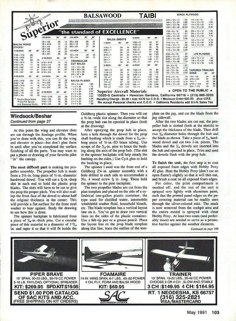
- Drill and tap the nose block for 1/4‑in. x 20 threads to accept the propeller shaft bolt. Drill 3/16‑in. holes in the top and bottom pivot blocks for the center pivot.
- Sand the blocks until they fit flat to the foam and glue the fuselage templates to both sides with contact cement.
Wings and elevator
- Cut the wing profile from 1/2‑in. foam board using the same method as the fuselage.
- Cut the elevator outline from 1/4‑in. foam‑core board.
- Glue wing and elevator templates to the top and bottom of each part with contact cement.
- Cut wing and elevator slots through the fuselage profile. Fit the wing and elevator in place, but do not epoxy them in until after surface finishing.
- Optionally, place a photo or drawing of your favorite pilot in the canopy area before finishing.
Propeller assembly
- Make the propeller hub from a section of hardwood dowel of suitable diameter (about 1/2‑in. diameter) cut to length. Cut a slot (about 5/32‑in. deep) in each end to accept the plastic prop blades. Scallop the front face of the dowel to about half the original thickness in the center to provide a flat bearing surface for the front steel washer.
- Fabricate a spinner backplate from 7/16‑in. thick pine: cut a circular piece 1‑1/16 in. in diameter and taper it to fit inside the Goldberg (or similar) plastic spinner. Cut a 1/8‑in. wide slot along the diameter so the prop hub can be epoxied in place.
- Epoxy the prop hub into the spinner backplate slot. Bore a hole through the dowel for the prop shaft bushing, made from a short piece (about 3/16‑in. long) of 1/4‑in. ID brass tubing. Use pine scraps to brace the bushing along the prop axis and secure with CyA (CA) glue.
- Fasten the spinner to the backplate with No. 4 wood screws (about 3/8 in. long) through holes drilled each side of the spinner.
- Make two prop blades from the sidewall of a cylindrical one‑gallon plastic container (distilled water, windshield washer fluid, bleach jugs, etc.). Use the blade template and a vertical layout line to transfer the outline to the jug sidewall and cut the blades out.
- Slot the propeller hub to accept the blade thickness. Drill two 1/16‑in. diameter holes through hub and blades. Insert two 1‑in. pieces of 1/16‑in. hardwood dowel as pins, epoxy them in place, then trim and sand flush.
Surface finishing
- Seal all exposed foam edges by brushing on Hobby Poxy #2 glue. Warm the Hobby Poxy slightly (do not use an open flame) to thin it, then brush on with an old soft brush. This seals the raw foam.
- Mask off the pilot compartment. Spray the rest of the unit very lightly with aluminum paint so the printed panel edges on the paper covering material are still visible through the silver mist.
- Remove the cockpit mask and spray the entire model with clear Hobby Poxy. Apply at least two coats (preferably more) for weather protection.
Pole mount and pivot
- The pole mount is cut from 7/8‑in. diameter dowel and tapered to fit inside a piece of 3/4‑in. schedule 40 standard pipe (a good choice for the pole). The mount can be adapted to other pole sizes if needed.
- Drill a 3/16‑in. diameter hole through the center of the pole mount. Insert two 3/8‑in. long, 3/16‑in. diameter hollow brass rivets into the hole at the top and bottom of the pole mount and glue them in place with CA. These rivets act as bearings.
- Glue two of the same type of hollow rivets to the top and bottom bearing blocks in the fuselage to mate with the pole mount bearings.
- Install a 1/4‑in. diameter steel rod as the axis rod and bend the top and bottom ends for retention. This rod serves as the central pivot for the fuselage assembly.
Final assembly
- Assemble and epoxy the wing and elevator through the fuselage slots.
- Install the propeller shaft: a 1/4‑in. x 20 hex head bolt (approximately 1‑1/2 in. long) serves as the shaft. Use three steel flat washers as thrust bearings between the bolt head and the prop hub assembly.
- Epoxy the 1/4‑in. hex head bolt into the shaft bearing block; be careful not to over‑tighten, as this will prevent the propeller from turning freely. Avoid getting epoxy on the washers or propeller hub.
- Install the propeller assembly on the bolt so the hub freewheels against the thrust washers.
- Trim and apply insignia and colors to the model as desired.
I trust you will enjoy building the Wind Direction Finder and will refer to it at your club field when choosing your direction for takeoffs and landings. I hope the fliers and spectators will enjoy it as much as we've enjoyed ours.
Transcribed from original scans by AI. Minor OCR errors may remain.

