
Modesty
L. F. Randolph
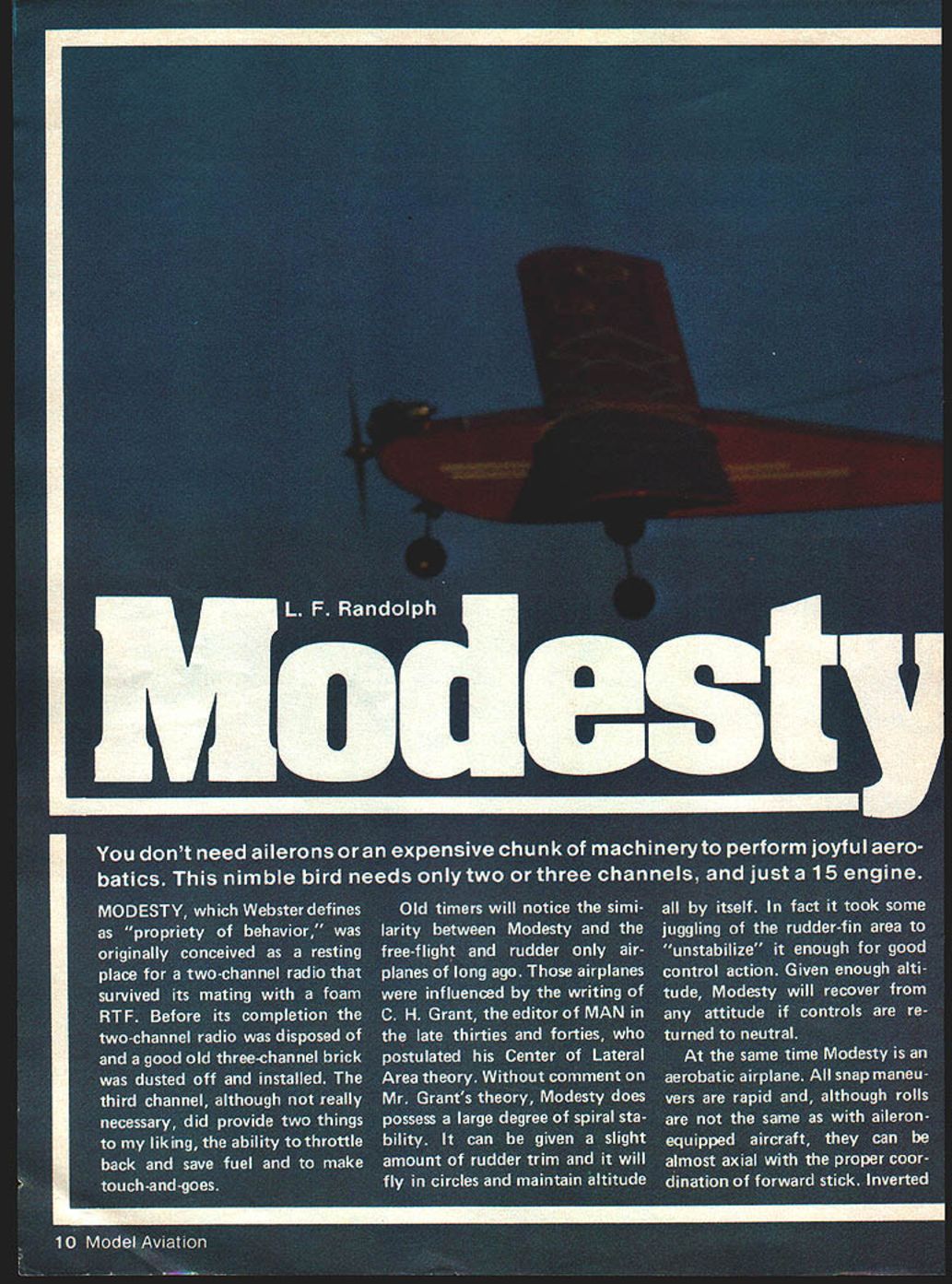
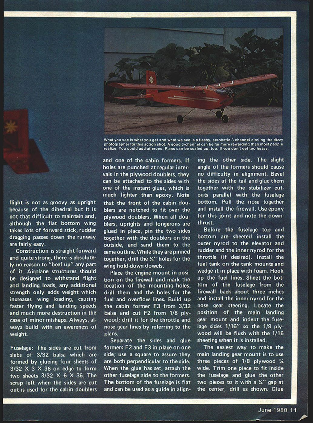
You don't need ailerons or an expensive chunk of machinery to perform joyful aerobatics. This nimble bird needs only two or three channels, and just a 15-size engine.
Modesty, which Webster defines as "propriety of behavior," was originally conceived as a resting place for a two-channel radio that survived its mating with a foam RTF. Before its completion the two-channel radio was disposed of and a good old three-channel brick was dusted off and installed. The third channel, although not really necessary, did provide two things to my liking: the ability to throttle back and save fuel, and the ability to make touch-and-goes.
Old-timers will notice the similarity between Modesty and the free-flight and rudder-only airplanes of long ago. Those airplanes were influenced by the writing of C. H. Grant, the editor of MAN in the late thirties and forties, who postulated his Center of Lateral Area theory. Without comment on Mr. Grant's theory, Modesty does possess a large degree of spiral stability. It can be given a slight amount of rudder trim and it will fly in circles and maintain altitude all by itself. In fact it took some juggling of the rudder-fin area to "unstabilize" it enough for good control action. Given enough altitude, Modesty will recover from any attitude if controls are returned to neutral.
At the same time Modesty is an aerobatic airplane. All snap maneuvers are rapid and, although rolls are not the same as with aileron-equipped aircraft, they can be almost axial with the proper coordination of forward stick. Inverted flight is not as groovy as upright because of the dihedral, but it is not that difficult to maintain; although the flat-bottom wing takes lots of forward stick, rudder-dragging passes down the runway are fairly easy.
Construction is straightforward and quite strong; there is absolutely no reason to "beef up" any part of it. Airplane structures should be designed to withstand flight and landing loads—any additional strength only adds weight, which increases wing loading, causing faster flying and landing speeds and much more destruction in the case of minor mishaps. Always build with an awareness of weight.
Fuselage
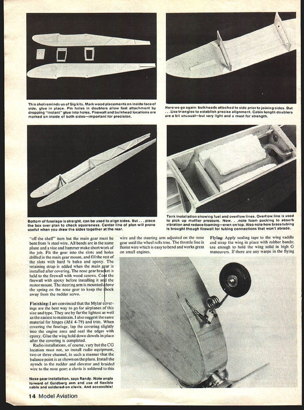
The sides are cut from slabs of 3/32" balsa which are formed by gluing four sheets of 3/32" x 3" x 36" on edge to form two sheets 3/32" x 6" x 36". The scrap left when the sides are cut out is used for the cabin doublers and one of the cabin formers. If holes are punched at regular intervals in the plywood doublers, they can be attached to the sides with one of the instant adhesives, which is much lighter than epoxy. Note that the front of the cabin doublers are notched to fit over the plywood doublers.
When all doublers, uprights and longerons are glued in place, pin the two sides together with the doublers on the outside, and sand them to the same outline. While they are pinned together, drill the 1/4" holes for the wing hold-down dowels.
Place the engine mount in position on the firewall and mark the location of the mounting holes; drill them and the holes for the fuel and overflow lines. Build up the cabin former F3 from 3/32" balsa and cut F2 from 1/8" plywood; drill it for the throttle and nose gear lines by referring to the plans.
Separate the sides and glue formers F2 and F3 in place on one side; use a square to assure they are both perpendicular to the side. When the glue has set, attach the other fuselage side to the formers. The bottom of the fuselage is flat and can be used as a guide in aligning the other side. The slight angle of the formers should cause no difficulty in alignment. Bevel the sides at the tail and glue them together with the stabilizer cutouts parallel with the fuselage bottom. Pull the nose together and install the firewall. Use epoxy for this joint and note the downthrust.
Before the fuselage top and bottom are sheeted, install the outer nyrod to the elevator and rudder and the inner nyrod for the throttle (if desired). Install the fuel tank on the tank mounts and wedge it in place with foam. Hook up the fuel lines. Sheet the bottom of the fuselage from the firewall back about three inches and install the inner nyrod for the nose gear steering.
Locate the position of the main landing gear mount and indent the fuselage sides 1/16" so the 1/8" plywood will be flush with the 1/16" sheeting when it is installed. The easiest way to make the main landing gear mount is to use three pieces of 1/8" plywood, 3/4" wide. Trim one piece to fit inside the fuselage and glue the other two pieces to it with a 1/4" gap at the center; drill as shown on the plans. Glue the mount assembly in position on the fuselage bottom and complete the cross-grain sheeting on top and bottom from the firewall aft.
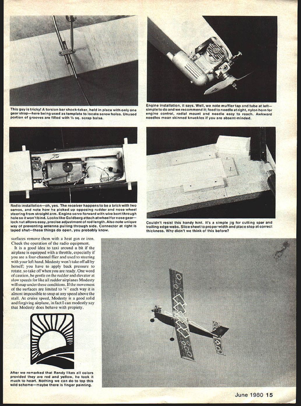
The engine can be mounted upright or on its side and the sheeting around the nose will depend on the type of mounting used. The engine can be mounted on the firewall and the sheeting done with it in place. For side mounting, the side of the fuselage in front of the firewall must be cut away to fit the engine.
Wing
Slice the ribs from medium to light quarter-grain balsa and pin them together in a block, then gang-sand them to the same outline. Select four of them and slice 1/16" from the top and bottom of each to receive the center section sheeting and enlarge the spar notches for the dihedral braces. Cut the webs from medium 1/16" balsa and the dihedral braces from 1/16" plywood. The trailing edge sheeting is stripped from 1/16" balsa sheet and the spars, leading and trailing edges can be stripped from appropriate balsa sheet or purchased.
Cover the plan with wax paper and pin the main spar and trailing edge sheeting in position over the plan. Starting with the second center section rib, glue it in place and add the webs outboard of it, followed by the next rib and more webs, the next rib, etc., out to the tip. Glue the top main spar to the ribs and webs, add the top front spar and the wing can be removed from the plans. Build the other wing half in the same sequence.
When both halves are completed, bevel the spars, leading and trailing edges at the center to correspond with the dihedral angle (5 degrees) and join the halves with the dihedral braces; it may be necessary to trim the main spar notches slightly to accept the extensions of the dihedral braces. The top trailing edge sheeting is added after the trailing edge brace is in place. Sheet the center section with 1/16" balsa and add the 1/8" square trailing edge cap.
The tip is formed by cutting a 1-1/4" x 1" x 7" block of soft balsa in the end diagonal to form two rectangular pieces with a triangular cross-section. These are glued to the wing tips with the widest part at the top and the narrowest part even with the bottom of the wing. Wrap about half of a 12" sanding block with bond paper to keep it from cutting into the ribs and, using this part of the block over the ribs, sand the blocks to the airfoil section. They will then conform to the outline shown on the plans. Sand the completed wing and add the 1/16" wire at the trailing edge to protect it from the rubber bands that hold it to the fuselage.
Tips and notes:
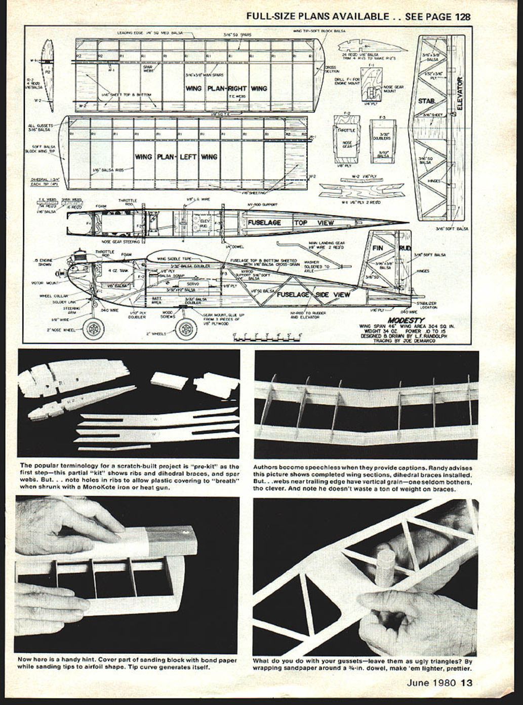
- Note holes in ribs to allow plastic coverings to "breathe" when shrunk with a MonoKote iron or heat gun.
- Authors become speechless when they provide captions. Randy advises that the picture shows completed wing sections with dihedral braces installed. Webs near the trailing edge may have vertical grain—one seldom bothers. Note he doesn't waste weight on braces.
- Cover part of a sanding block with bond paper while sanding tips to airfoil shape; the tip curve generates itself.
- What do you do with your gussets—leave them as ugly triangles? By wrapping sandpaper around a 3/4" dowel, make them lighter and prettier.
Tail Group
Build the stabilizer and fin from medium 3/16" square balsa; it can be purchased or stripped from sheet stock. There is a 1/32" plywood doubler on the inside of the trailing edge to add strength in this area; do not omit it. The leading edge of the fin is extended slightly below the bottom to fit into a slot on top of the fuselage.
Cut the elevator and rudder from soft 3/16" sheet balsa—the lighter the better. Locate the spots on them where the horns will be mounted and treat these areas with Hot Stuff or similar adhesive to harden them for the mounting hardware. Tape or pin the moving surfaces to their fixed counterparts and sand them smooth with rounded edges. They will be hinged when they are covered.
Landing Gear
The nose gear and mount is an "off-the-shelf" item, but the main gear must be bent from 3/32" steel wire. All bends are in the same plane and a vise and hammer make short work of the job. Fit the gear into the slots and holes drilled in the main gear mount, and fill the rest of the slots with hard 1/8" balsa and epoxy. The retaining strap is added when the main gear is installed after covering. The nose gear bracket is held to the firewall with wood screws. Coat the firewall with epoxy before installing it and the motor mount.
Mount the steering arm above the spring on the nose gear to keep the shock away from the rudder servo.
Finishing
I am convinced that the Mylar coverings are the best way to go for airplanes of this size and type. They are by far the lightest as well as the easiest to maintain. I also suggest the same material for hinges (MA 4-79) and trim. When covering the fuselage, lap the covering slightly into the engine area and seal the edges with epoxy. Glue the wing hold-down dowels in place after the covering is completed.
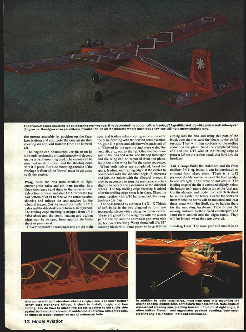
Radio installations, of course, vary, but the CG location must not—so install radio equipment, two- or three-channel, in such a manner that the balance point is as shown on the plans. Install the pushrods to the rudder and elevator and braided wire to the nose gear; a clevis is soldered to this wire and the steering arm adjusted on the nose gear until the wheel rolls true. The throttle line is florist wire, which is easy to bend and works great on small engines.
Flying
Apply sealing tape to the wing saddle and strap the wing in place with rubber bands; use enough to hold the wing solid in high-G maneuvers. If there are any warps in the flying surfaces, remove them with a heat gun or iron. Check the operation of the radio equipment.
It is a good idea to taxi around a bit if the airplane is equipped with a throttle, especially if you are a four-channel flier and used to steering with your left hand. Modesty won't take off all by herself; you have to apply back pressure to rotate, so take off when you are ready.
One word of caution: be gentle on the rudder and elevator at slow speeds, for, like all rudder airplanes, Modesty will snap under these conditions. If the movement of the surfaces is limited to 1/4" each way it is almost impossible to snap at any speed above the stall. At cruise speed, Modesty is a good, solid and forgiving airplane; in fact I can modestly say that Modesty does behave with propriety.
Transcribed from original scans by AI. Minor OCR errors may remain.

