
Mods to DC/DC Super Charger
By Bob Kopski
Introduction
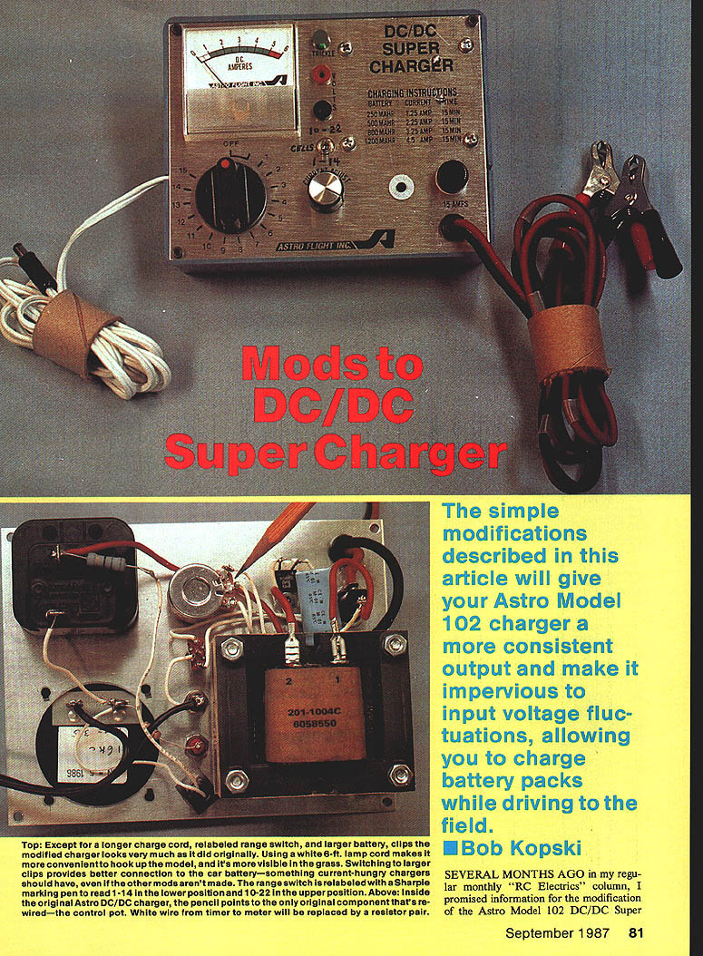
The simple modifications described here will give your Astro Model 102 DC/DC Super Charger a more consistent output and make it much less sensitive to input voltage fluctuations. That allows you to charge battery packs while driving to the field (with the engine running) without large variations in charging current.
This modification is easy to install and will significantly improve the performance of an already very good product for most applications.
About the Astro Model 102
The Astro Super Charger is essentially an adjustable voltage converter. It takes a 12‑volt input (from an auto battery) and converts it to lower or higher voltages via the range switch and the adjustable control knob. If you are charging a small pack you set a lower output; if you need higher voltage for many cells you set a higher output.
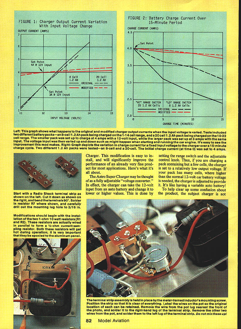
Note: the charger is not automatic — it does not sense battery condition and shut off. It uses a standard 15‑minute timer to control charge duration (timed charging). The charger is regulated to a selected battery charge current but, in the stock unit, that set current can vary with the battery terminal voltage and the auto battery voltage. The modification described here stabilizes the selected charge current so you do not have to continually readjust the control during the timed cycle.
The modification — overview
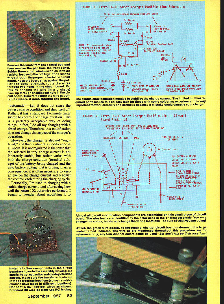
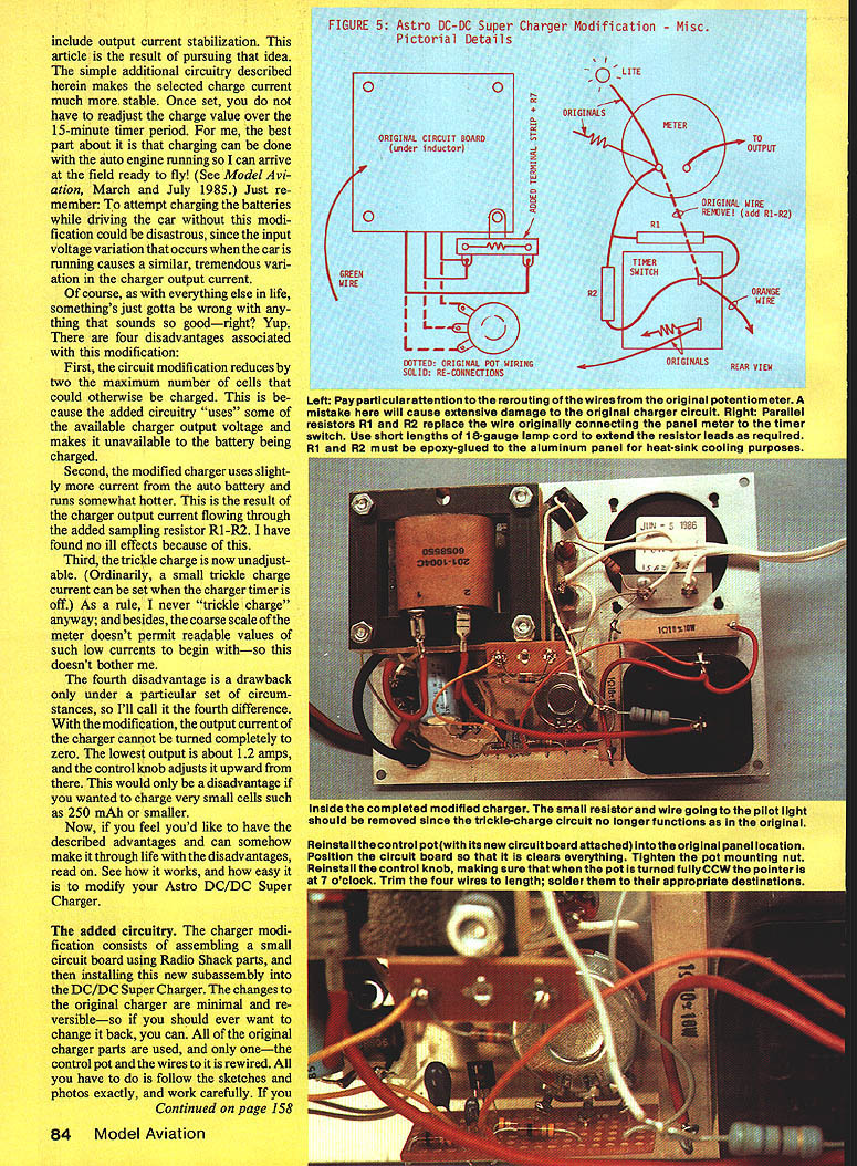
The modification adds a small circuit card that provides current sampling and feedback to stabilize the charger output current. The main change is the installation of two 1‑ohm, 10‑watt resistors (R1 and R2) wired in parallel to form a 1/2‑ohm current‑sampling resistor. A PNP transistor on the small circuit card senses the voltage across this sampling resistor and, via the rewired control pot and an adjustable divider (R3–R4), provides feedback to the original charger electronics to maintain the selected current.
Most of the added components are assembled on a small piece of circuit board (made from a cut terminal strip). The changes to the original charger are minimal and reversible — the original parts are used and only the control pot and its wires are rewired.
Advantages and limitations
Advantages
- Much more stable selected charge current over the 15‑minute timer period.
- Permits charging with the auto engine running without large current fluctuations due to alternator voltage variation.
- Once set, the charge current remains essentially constant during the charge cycle.
Disadvantages / differences
- The modification reduces the maximum number of cells that can be charged by about two cells because the added circuitry uses some of the available charger output voltage.
- The modified charger draws slightly more current from the auto battery and runs hotter because the output current flows through the sampling resistor.
- The trickle charge is no longer adjustable (a minor issue for most users).
- The lowest obtainable output current is about 1.2 A; the control cannot be turned completely to zero. This matters only if you want to charge very small cells (e.g., 250 mAh or smaller).
Installation notes and cautions
- The two 1‑ohm, 10‑watt resistors will get hot during operation; make sure they are exposed to the aluminum can for cooling.
- Work carefully. If you are not comfortable with soldering, get assistance. Mistakes could damage the charger.
- Wire colors mentioned in the procedure are for reference only — you may use different colors but do not mix up wiring locations.
- The modification will void the product warranty.
Assembly and wiring highlights
- Cut a Radio Shack terminal strip down as needed and bend the terminals 90°. Solder resistor R7 to the terminal strip and carefully drill the mounting lug hole to 3/16 in.
- Mount the terminal strip assembly so it is held in place by the inductor’s mounting screw and clear of other parts.
- Label the pot wires before removing them so their original locations are known. Remove the wire from the pot lug nearest the front and solder it to the right‑hand lug of the terminal strip. Remove the other two wires from the pot and solder them to the left lug of the terminal strip. Do not mix these up.
- Remove the knob and the pot from the front panel. Solder three short wires (leftover resistor leads work well) to the pot lugs and run the wires through the proper holes in the circuit board. Keep the board snug against the pot. For additional strength, route each wire through two holes in the circuit board in a U shape and solder where it passes through.
- Install all other new components on the circuit board per the assembly drawing. Observe capacitor and diode polarities, and verify transistor lead orientation (different transistor types may have different lead positions).
- Connect 6‑in lead‑out wires as shown in the assembly drawing. Standard RC wire is suitable.
- Attach the green wire directly to the original charger circuit board underneath the large metal‑framed inductor.
- R7 on the terminal strip compensates for the “missing” pot resistance when the original pot is rewired.
How it works (brief)
- The modified charger output current flows through the 1/2‑ohm sampling resistor (R1–R2). The voltage across this resistor is proportional to the charge current.
- The small circuit card contains a PNP transistor whose base‑emitter junction senses a portion of that sampled voltage (selected by R3–R4, where R4 is the original 10K control pot).
- When the sampled voltage causes about 0.6 V across the base‑emitter junction, the transistor conducts and applies a control signal to the original charger electronics at the original pot connection.
- If the chosen charge current tends to rise (for example, when the car engine and alternator raise the input voltage), the transistor circuit instructs the charger electronics to reduce output to maintain the set current. If the charge current drops (for example, as the battery voltage rises), the circuit adjusts to increase output. The action is fast and automatic.
- R5 prevents excessive base current. R6, C1, C2, and D1 provide filtering so the new and original electronics work properly.
Using the modified Super Charger
- Turn the current control down to the minimum.
- Select the range switch setting corresponding to the number of cells being charged.
- Connect the charger clips to the auto battery and the output cable to the model battery.
- Turn the timer switch fully clockwise.
- Set the current control knob for the desired current meter reading.
That's it — once set, the unit maintains the selected current during the timing period.
Thoughts and suggestions
- Several chargers have been modified using this information and have worked as described. Extensive field testing was done.
- The modification is not for beginners but is straightforward for those with reasonable soldering skill and experience.
- You may notice charger current variation when an operating transmitter is brought near; radio signals can interfere with the charger electronics. Avoid doing this.
- With a constant-timed current, flight durations for the same model and conditions will become very consistent.
- Remember: modifying the charger voids the warranty.
Parts List
Part - Description - Radio Shack Pt. No.
- R1 — 1 ohm, 10 watt resistor — 271‑131
- R2 — 1 ohm, 10 watt resistor — 271‑131
- R3 — 2.2 KΩ, 1/4 watt resistor — 271‑125
- R4 — 10 KΩ control pot (original charger output control) — 271‑139
- R5 — 1 KΩ, 1/4 watt resistor — 271‑132
- C1 — 1.0 µF, 35 V tantalum capacitor — 272‑1434
- C2 — 22 µF, 16 V tantalum capacitor — 272‑1437
- Q1 — PNP transistor (any of MPS2907, MPS3638, 2N2907, 2N2909, 2N3906) — 276‑2023 / 276‑2032 / 276‑2022
- D1 — Silicon diode (1N914, 1N4148, or 1N4448) — 276‑1122
- Miscellaneous: PC board cut from terminal strip; star washer 3/16 in. inside dia.; large auto battery clips; six ft. white 18‑gauge lamp cord (optional, RS 270‑344); epoxy (Devcon 2‑Ton white slow cure).
Estimated time: three to four hours.
Contact
Please forward any comments or questions (with SASE) to: Bob Kopski 25 West End Dr. Lansdale, PA 19446
Transcribed from original scans by AI. Minor OCR errors may remain.

