
Mohawk Pinto
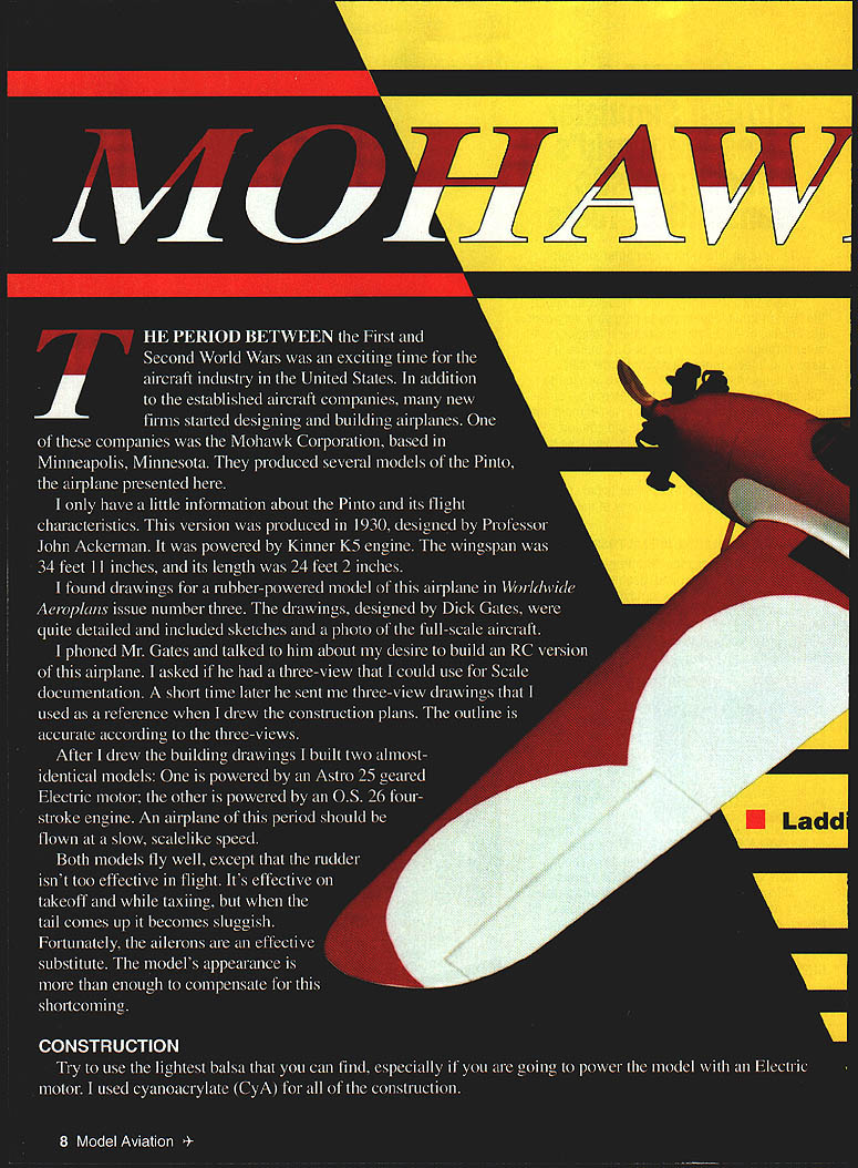
THE PERIOD BETWEEN the First and Second World Wars was an exciting time for the aircraft industry in the United States. In addition to the established aircraft companies, many new firms started designing and building airplanes. One of these companies was the Mohawk Corporation, based in Minneapolis, Minnesota. They produced several models of the Pinto, the airplane presented here.
I have only a little information about the Pinto and its flight characteristics. This version was produced in 1930, designed by Professor John Ackerman. It was powered by a Kinner K5 engine. The full-scale wingspan was 34 ft 11 in and its length was 24 ft 2 in.
I found drawings for a rubber-powered model of this airplane in Worldwide Aeroplans, issue number three. The drawings, by Dick Gates, were quite detailed and included sketches and a photo of the full-scale aircraft. I phoned Mr. Gates and asked if he had a three-view I could use for scale documentation. A short time later he sent three-view drawings that I used as a reference when I drew the construction plans. The outline of the model is accurate according to those three-views.
After I drew the building drawings I built two almost-identical models: one powered by an Astro .25 geared electric motor; the other by an O.S. .26 four-stroke engine. An airplane of this period should be flown at a slow, scale-like speed.
Both models fly well, except that the rudder isn't very effective in flight. It's effective on takeoff and while taxiing, but when the tail comes up it becomes sluggish. Fortunately, the ailerons are an effective substitute. The model's appearance is more than enough to compensate for this shortcoming.
Construction
Try to use the lightest balsa you can find, especially if you plan to power the model with an electric motor. I used cyanoacrylate (CyA) for all of the construction.
Wing
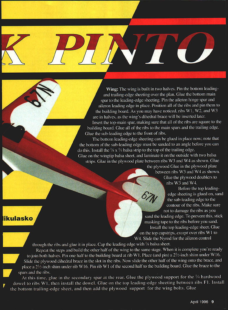
- The wing is built in two halves.
- Pin the bottom leading- and trailing-edge sheeting over the plan.
- Glue the bottom main spar to the leading-edge sheeting.
- Pin the aileron hinge spar and aileron leading edge in place.
- Position all ribs and pin them to the building board. Ribs W1, W2, and W3 are in halves; the wing's plywood dihedral brace will be inserted later.
- Insert the top main spar, making sure all ribs are square to the building board. Glue all ribs to the main spars and the trailing edge. Glue the sub-leading edge to the front of the ribs.
- Glue the bottom leading-edge sheeting in place. Note: the bottom of the sub-leading edge must be sanded to an angle before you do this.
- Install the 1/8 x 1/4 in balsa strip on top of the trailing edge.
- Glue on the wingtip balsa sheet and laminate it on the outside with two balsa strips.
- Glue in the plywood plate between ribs W3 and W4 and glue plywood doublers to ribs W3 and W4.
- Before gluing the top leading-edge sheeting, sand the sub-leading edge to the contour of the ribs. To avoid damaging the ribs, stick masking tape to them before sanding.
- Install the top leading-edge sheet. Glue on the top capstrips, except over ribs W1 to W4.
- Slide the Nyrod for the aileron control through the ribs and glue it in place. Cap the leading edge with 1/8 in balsa sheet.
- Repeat the steps to build the other half of the wing to the same stage. When both halves are complete you are ready to join them:
- Pin one half to the building board at rib W1.
- Place and pin a 2-1/2 in shim under rib W16.
- Slide the plywood dihedral brace into the slot in the ribs.
- Slide the other half of the wing onto the brace and place a 2-1/2 in shim under rib W16 of that half.
- Pin rib W1 of the second half to the building board.
- Glue the brace to the spars and ribs.
- Glue in the secondary spar at the rear.
- Glue the plywood support for the 1/4 in hardwood dowel to ribs W1, then install the dowel.
- Glue on the top leading-edge sheeting between ribs F1.
- Install the bottom trailing-edge sheet, then add the plywood support for the wing bolts.
- Glue on the top sheeting between ribs W2. Complete the top by gluing capstrips over ribs W3 and W4.
- Remove the wing from the building board and glue in the bottom secondary spar.
- Between ribs W1, glue in the plywood support plate for the landing gear.
- Finish the wing by adding all remaining capstrips and sheeting as shown on the drawing.
- Sand the wing to prepare it for covering, then set it aside.
Tail Surfaces
- Because the model has a relatively short nose, build the tail surfaces from the lightest balsa available.
- Cut the tail-surface shapes from 1/16 in balsa sheet.
- On one side of the sheet, add the leading and trailing edges made from 1/8 in balsa strips and glue false ribs between them. Repeat on the other side.
- Finish-sand everything to an airfoil shape.
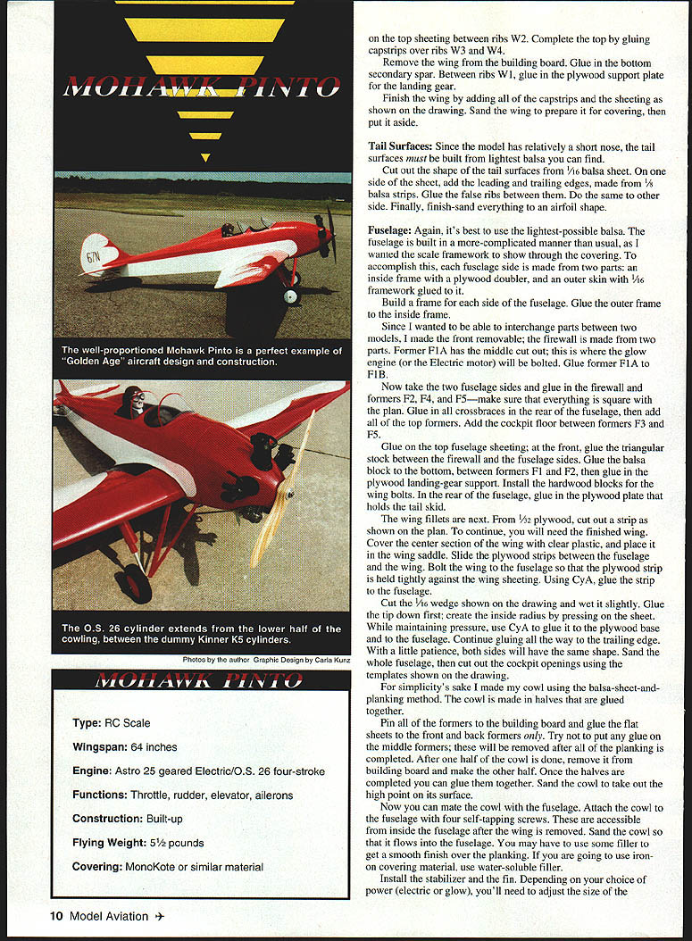
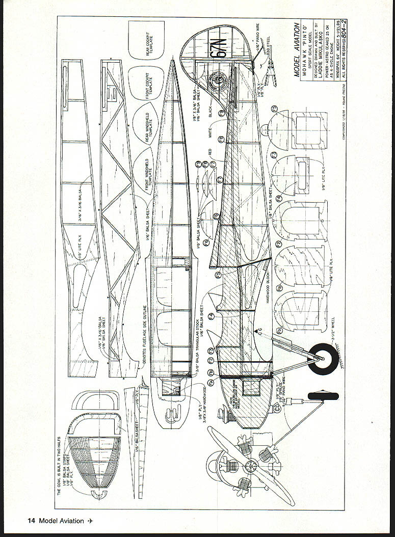
Fuselage
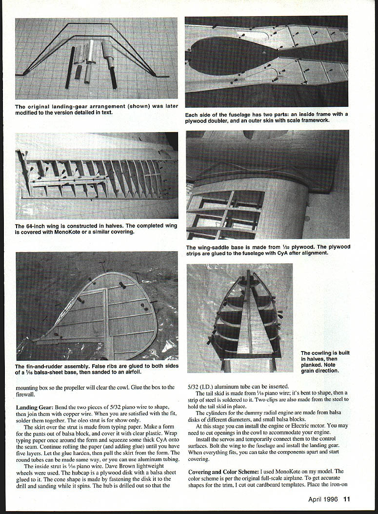
- Use the lightest balsa possible. The fuselage is built so the scale framework shows through the covering: each fuselage side is made from two parts—an inside frame with a plywood doubler and an outer skin with 1/16 in framework glued to it.
- Build a frame for each side of the fuselage, then glue the outer frame to the inside frame.
- To allow interchangeability of parts between two models, the front is made removable. The firewall is in two parts: former F1A (with its middle cut out for the glow engine or to bolt the electric motor) and F1B. Glue F1A to F1B.
- Take the two fuselage sides and glue in the firewall and formers F2, F4, and F5—ensure everything is square with the plan.
- Glue in all crossbraces in the rear of the fuselage, then add all top formers.
- Add the cockpit floor between formers F3 and F5.
- Glue on the top fuselage sheeting; at the front glue triangular stock between the firewall and fuselage sides.
- Glue a balsa block to the bottom between formers F1 and F2, then glue in the plywood landing-gear support.
- Install hardwood blocks for the wing bolts.
- In the rear of the fuselage, glue in the plywood plate that holds the tail skid.
- Wing fillets:
- From 1/32 in plywood, cut out the strip shown on the plan. You will need the finished wing.
- Cover the center section of the wing with clear plastic and place it in the wing saddle.
- Slide the plywood strips between the fuselage and the wing and bolt the wing to the fuselage so the plywood strip is held tightly against the wing sheeting.
- Using CyA, glue the strip to the fuselage.
- Cut the 1/16 in wedge shown on the drawing, wet it slightly and glue the tip down first. Create the inside radius by pressing on the sheet; while maintaining pressure, use CyA to glue it to the plywood base and the fuselage. Continue gluing all the way to the trailing edge. With patience, both sides will have the same shape.
- Sand the entire fuselage, then cut out the cockpit openings using the templates shown on the drawing.
- Cowl:
- The cowl is made by balsa-sheet-and-planking method in halves.
- Pin the formers to the building board and glue the flat sheets to the front and back formers only. Avoid glue on the middle formers; these are removed after planking is completed.
- After one half is done, remove it and make the other half. Glue both halves together and sand to remove high points.
- Mate the cowl to the fuselage and attach it with four self-tapping screws (accessible from inside the fuselage after the wing is removed).
- Sand the cowl so it flows into the fuselage; use filler for a smooth finish over the planking. If using iron-on covering, use water-soluble filler.
- Install the stabilizer and fin. Depending on your chosen power (electric or glow), adjust the size of the motor-mounting box so the propeller clears the cowl. Glue the box to the firewall.
Landing Gear
- Bend two pieces of 5/32 in piano wire to shape, then join them with copper wire. When satisfied with the fit, solder them together. The oleo strut is for show only.
- The skirt (pants) over the strut is made from typing paper:
- Make a form from a balsa block and cover it with clear plastic.
- Wrap typing paper once around the form and squeeze thick CyA onto the seam.
- Continue rolling the paper and adding glue until you have five layers.
- Let the glue harden, then pull the skirt from the form.
- Round tubes can be made the same way or you can use aluminum tubing.
- The inside strut is 1/16 in piano wire.
- Dave Brown lightweight wheels were used. The hubcap is a plywood disk with a balsa sheet glued to it; the cone shape is formed by fastening the disk to a drill and sanding while it spins. Drill out the hub so a 5/32 in I.D. aluminum tube can be inserted.
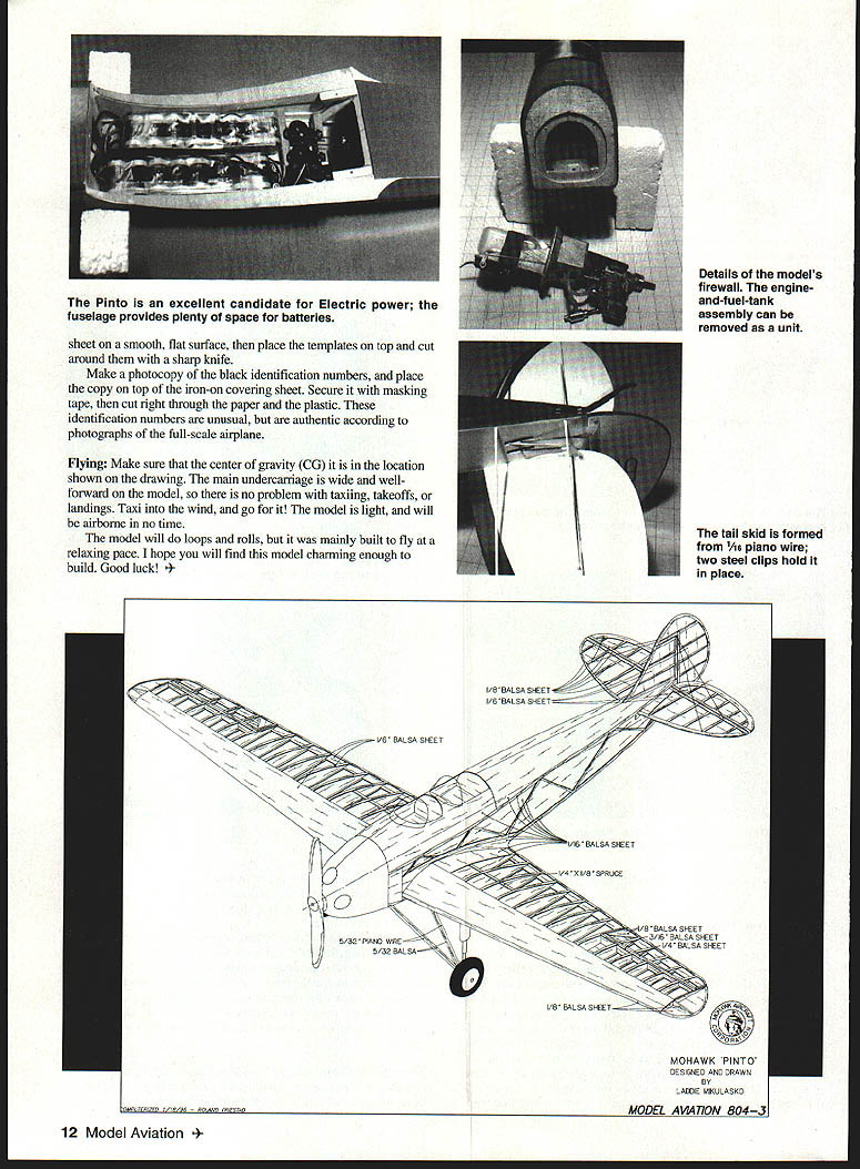
- The tail skid is made from 1/16 in piano wire; bend to shape and solder a strip of steel to it. Two steel clips hold the tail skid in place.
Engine and Scale Details
- Dummy radial cylinders are made from balsa disks of different diameters and small balsa blocks.
- At this stage you can install the engine or electric motor. You may need to cut openings in the cowl to accommodate your motor.
- Install the servos and temporarily connect them to the control surfaces.
- Bolt the wing to the fuselage and install the landing gear. When everything fits, disassemble the components and start covering.
Covering and Color Scheme
- I used MonoKote on my model. The color scheme follows the original full-scale airplane.
- To get accurate shapes for the trim, cut cardboard templates first.
- Place the iron-on sheet on a smooth, flat surface, then place the templates on top and cut around them with a sharp knife.
- For the identification numbers: make a photocopy of the black numbers, place the copy on top of the iron-on covering sheet, secure with masking tape, then cut through the paper and the plastic. These identification numbers are unusual but are authentic according to photographs of the full-scale airplane.
Flying
- Make sure the center of gravity (CG) is in the location shown on the drawing.
- The main undercarriage is wide and well forward on the model, so taxiing, takeoffs, and landings are straightforward.
- Taxi into the wind and apply power; the model is light and will be airborne quickly.
- The model will do loops and rolls, but it was mainly built to fly at a relaxing, scale-like pace.
- Note: the rudder becomes less effective when the tail is up; rely on ailerons in that situation.
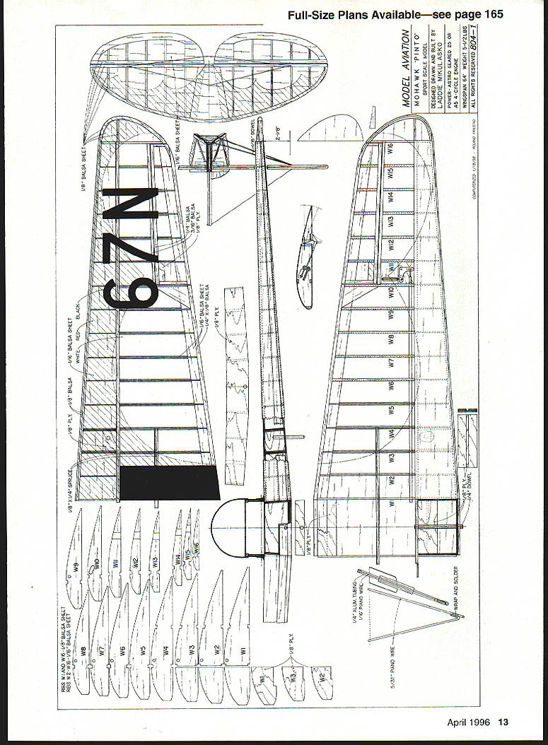
Full-size plans available—see page 165
- Type: RC
- Scale: (not specified)
- Wingspan: 64 in (model)
- Full-scale Wingspan: 34 ft 11 in
- Full-scale Length: 24 ft 2 in
- Engine (model): Astro .25, geared; Electric / O.S. .26 four-stroke
- Functions: throttle, rudder, elevator, ailerons
- Construction: built-up
- Flying weight: 5 lb
- Covering: MonoKote (or similar material)
Transcribed from original scans by AI. Minor OCR errors may remain.

