
Monoboom 1/2A
Michael Hoffelt
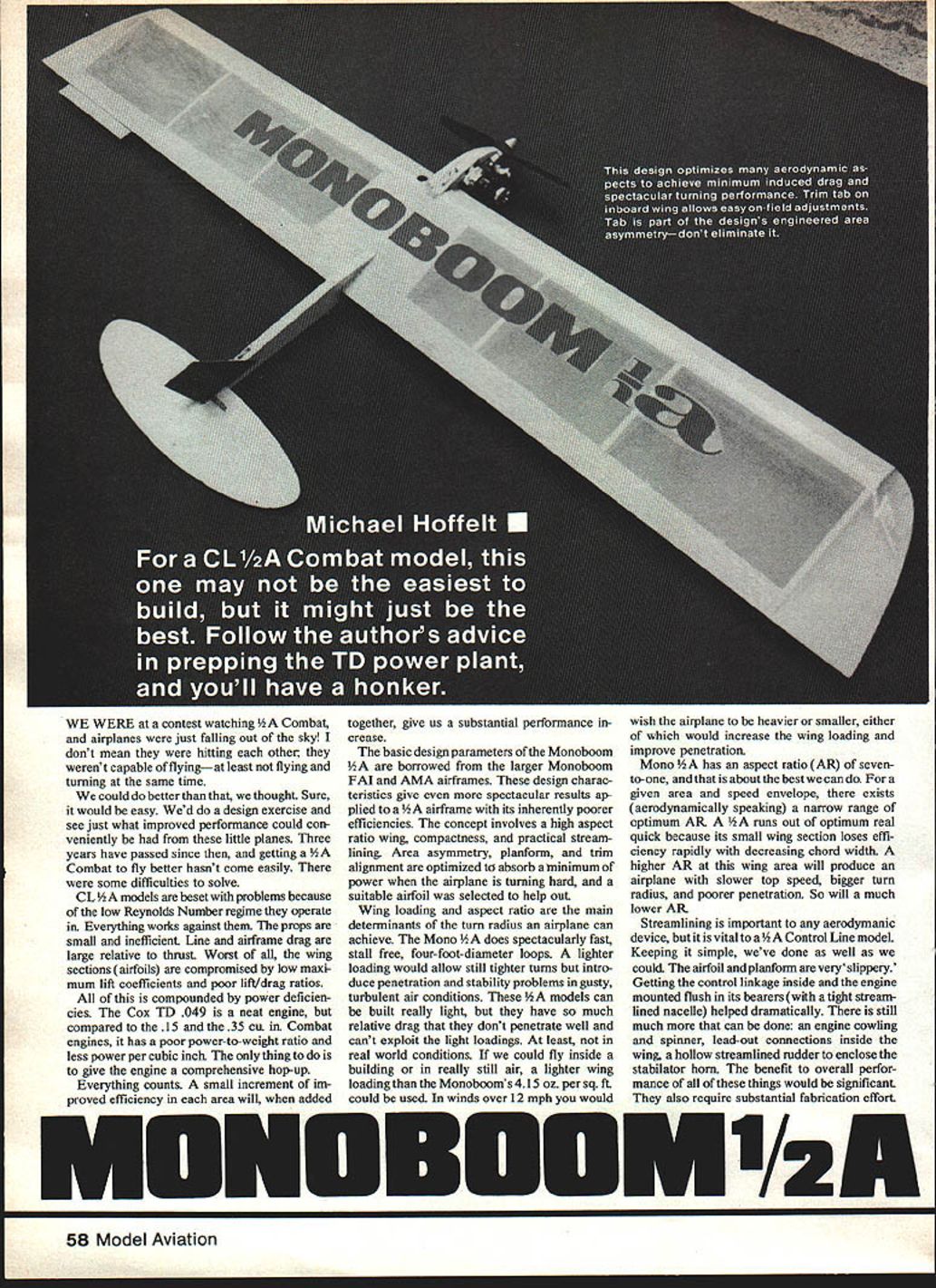
For a CL 1/2A Combat model, this one may not be the easiest to build, but it might just be the best. Follow the author's advice in prepping the TD power plant, and you'll have a honker.
We were at a contest watching 1/2A Combat, and airplanes were just falling out of the sky! I don't mean they were hitting each other, they weren't capable of flying—at least not flying and turning at the same time.
We could do better than that, we thought. Sure, it would be easy. We'd do a design exercise and see just what improved performance could conveniently be had from these little planes. Three years have passed since then, and getting 1/2A Combat to fly better hasn't come easily. There were some difficulties to solve.
CL 1/2A models are beset with problems because of the low Reynolds-number regime they operate in. Everything works against them. The props are small and inefficient. Line and airframe drag are large relative to thrust. Worst of all, the wing sections (airfoils) are compromised by low maximum lift coefficients and poor lift/drag ratios.
All of this is compounded by power deficiencies. The Cox TD .049 is a neat engine, but compared to the .15 and the .35 cu. in. Combat engines, it has a poor power-to-weight ratio and less power per cubic inch. The only thing to do is to give the engine a comprehensive hop-up.
Everything counts. A small increment of improved efficiency in each area will, when added together, give us a substantial performance increase.
The basic design parameters of the Monoboom 1/2A are borrowed from the larger Monoboom FAI and AMA airframes. These design characteristics give even more spectacular results applied to a 1/2A airframe with its inherently poorer efficiencies. The concept involves a high aspect-ratio wing, compactness, and practical streamlining. Area asymmetry, planform, and trim alignment are optimized to absorb a minimum of power when the airplane is turning hard, and a suitable airfoil was selected to help out.
Wing loading and aspect ratio are the main determinants of the turn radius an airplane can achieve. The Mono 1/2A does spectacularly fast, stall-free, four-foot-diameter loops. A lighter loading would allow still tighter turns but introduce penetration and stability problems in gusty, turbulent air conditions. These 1/2A models can be built really light, but they have so much relative drag they don't penetrate well and can't exploit the light loadings—at least, not in real-world conditions. If we could fly inside a building or in really still air, a lighter wing loading than the Monoboom's 4.15 oz per sq. ft. could be used. In winds over 12 mph you would wish the airplane to be heavier or smaller, either of which would increase the wing loading and improve penetration.
Mono 1/2A has an aspect ratio (AR) of seven-to-one, and that is about the best we can do. For a given area and speed envelope, there exists (aerodynamically speaking) a narrow range of optimum AR. A 1/2A runs out of optimum real quick because its small wing section loses efficiency rapidly with decreasing chord width. A higher AR at this wing area will produce an airplane with slower top speed, bigger turn radius, and poorer penetration. So will a much lower AR.
Streamlining is important to any aerodynamic device, but it is vital to a 1/2A control-line model. Keeping it simple, we've done as well as we could. The airfoil and planform are very "slippery." Getting the control linkage inside and the engine mounted flush in its bearers (with a tight, streamlined nacelle) helped dramatically. There is still much more that can be done: an engine cowling and spinner, lead-out connections inside the wing, a hollow streamlined rudder to enclose the stabilator horn. The benefit to overall performance of all of these things would be significant. They also require substantial fabrication effort. Perhaps it is better to have an airplane to fly than one that never gets built!
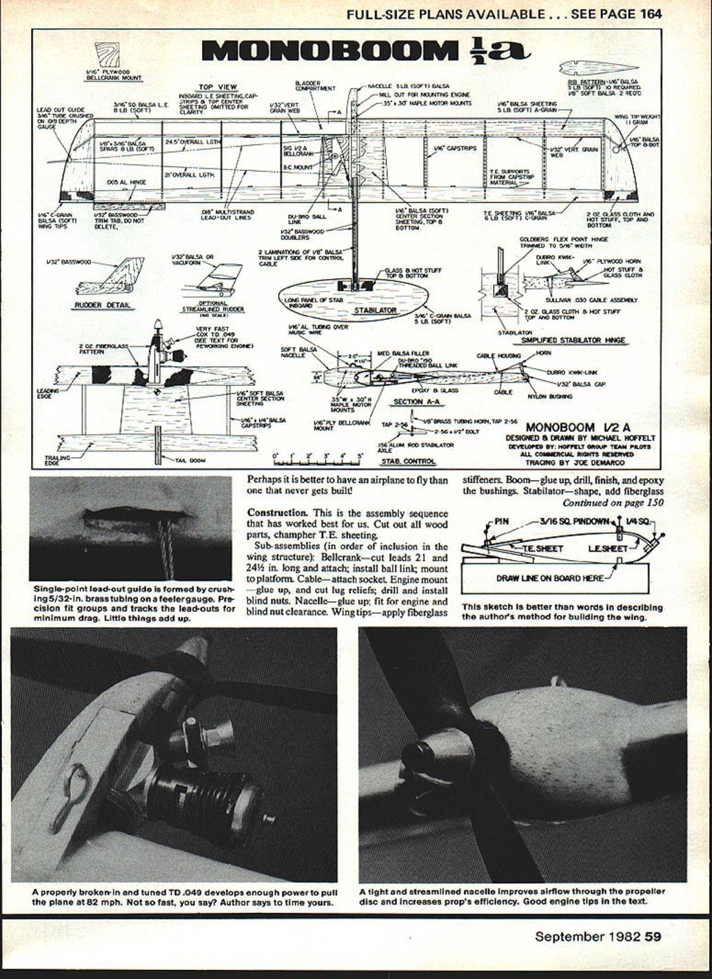
Construction
This is the assembly sequence that has worked best for us. Cut out all wood parts and chamfer trailing-edge (T.E.) sheeting.
Sub-assemblies
- Bellcrank — cut leads 21 and 24½ in. long and attach; install ball link; mount to platform.
- Cable — attach socket.
- Engine mount — glue up, and cut lug reliefs; drill and install blind nuts.
- Nacelle — glue up; fit for engine and blind nut clearance.
- Wingtips — apply fiberglass stiffeners.
- Boom — glue up, drill, finish, and epoxy the bushings.
- Stabilator — shape, add fiberglass stiffeners, finish, and assemble to boom.
Assembly
- Mark and cut lead-out holes in the inboard ribs.
- Pin bottom spar to the work board. Lay in ribs. Make a full-span jig of the proper height, and position bottom trailing edge on the jig 1/4 in. behind the ribs. Square and pin ribs at the trailing edge.
- Work in top spar, square ribs, and space center rib with engine mount. Use a cyanoacrylate glue (CA) on all joints.
- Cut nose off the rib behind the bladder compartment. Glue on the leading edge. Pull pins from the bottom trailing edge. Glue on the top trailing edge with 30-min epoxy. Pin every inch. Glue on the top leading edge and sheeting with 30-min epoxy. Pin every inch.
- A good trick is to pin through a full-span strip of 3/16 sq. at T.E., L.E., and spar—this will hold the 1/16 sheet in place like a vise and will keep it straight.
- Add spar webbing, trailing edge supports, and cap strips. Flip wing upside down, and re-pin. Trim leading edge in bladder compartment; add spar web in this area. Glue the cut-off rib to the web in the bladder area. The leading-edge sheeting goes on with epoxy. When all is dry, check for any loose joints.
- Install bellcrank assembly. Notch wing for cable outlet. Drill through rib, and install cable. Glue on center sheeting.
- Sand wing. Cut away sheeting for and install the engine mount. Mask blind nuts, and glue on nacelle with epoxy. Fiberglass the front end to the pattern shown on the plans.
- Cut bladder access. Finish the wingtips and the lead-out guide. Add tip weight. Cover the wing. Fit the boom. Cut cable housing, and epoxy it. When cured, solder the connector. Add the fuel pinch-off. Use contact cement for the trim tab and rudder.
Engine
Now that the plane is finished, grab a TD .049. Err… well, wait a minute. If you want your Mono 1/2A to really smoke, your TD will probably need a little tuning. There is a great deal of myth floating around regarding the extraction of horsepower from these engines, so I spent a few weekends with the test stand sorting through the possibilities.
Right off, take your new motor apart and wash out any metal bits. Throw the needle-valve assembly in the trash and go buy a fine-threaded replacement unit made by Kustom Kraftsman or Ace RC. While you're shopping get a half dozen GloBee competition glow heads and a connecting-rod reset tool. The connecting-rod retaining socket on the piston is the weakest link in the engine. This socket will pound itself sloppy during a break-in and will have to be reset. Several reset tools are available at your dealer. I prefer the unit made by Davis Diesel Development as it includes a jig to prevent piston distortion. Drill the venturi to .125 in., and carefully reassemble the engine with two gaskets under the glow head.
It seems that the three most pertinent factors in .049 engine performance are fuel, compression, and the state of the engine's break-in. These factors are closely interrelated. A change in one necessitates adjustment of the others to obtain optimum power.
First, there is no such thing as a fuel that is too hot for TD .049s—not with traditional ingredients and an open exhaust configuration, anyway. These little engines have a very high surface-to-displacement ratio, and they most always run too cold. The practical minimum in the horsepower search is 40% nitro. Best tested was 75% nitro, 10% propylene oxide, and 15% Klotz. This was generally six to eight hundred rpm faster than 40%, putting peak speeds in the 22,000-rpm range.
Even with this hottest of fuels, the cylinder-head temperature didn't go over 390 degrees at the best power setting. This is below what is needed for best thermal efficiency, and it indicates that we could use even hotter fuel if there was any. I've been told that the current Klotz oil has a substantial ester content. I don't know that to be so, but it behaved as though it did, lubricating well and not burning even at leanish settings.
If you have read the TD instruction sheet, you might think that a couple of rich runs on the ground will have your new .049 Combat engine ready. It will if you always use 10% nitro. To exploit high-nitro fuels and make horsepower, a more protracted break-in is necessary.
The TD piston grows as it is heat-cycled by running and cooling. Higher temperature ranges of high-nitro fuels make it grow still more. What is needed is enough running to stabilize the swelling piston—and wear it to a proper fit in its cylinder. The process can't be rushed. If lots of nitro and lean settings are applied too soon, the piston will gall—and show a dull, scratched surface. This is actually from the swollen piston pressing so hard against the cylinder wall that metal is rubbed and torn off. If it galls badly, it will so distort the surfaces of the piston and the cylinder that the engine will never make much power.
Start with a medium-nitro fuel and two gaskets under the glow head. Use a prop cut in diameter sufficiently to allow approximately 18,000 rpm when the engine is just breaking into two-cycle. Run the engine about three minutes at a time, checking the piston for galling between runs. If it starts to gall, richen the setting and run it that way until the piston appears polished. Tight engines can have their break-in hastened by applying Fox Lustrox (a polishing abrasive) to the piston between runs. Don't run the Lustrox through by putting it in the venturi. Just mix a little with fuel and dab it into the exhaust port between runs.
When the engine will hold a peak power setting for three minutes (without sagging or galling the piston), change to the high-nitro fuel you will be using to fly with. Remove one of the two head gaskets if your hot fuel is 40% nitro or less. Go through the break-in running sequence until a full-power setting can be held for three minutes without trauma. Now you have that elusive piston/cylinder fit so sought after by 1/2A enthusiasts.
For best performance, the compression must be set for each particular fuel mix. This is done by adding or removing gaskets under the glow head. The greater the fuel's nitro content, the lower the compression must be (more washers). The Globe Racing glow head is better than the one which comes with the engine. It consistently tests 200+ rpm faster than stock, has a mechanically superior clamping arrangement, and is less costly.
The final compression setting is best done on the test stand. You will need a good tachometer—one that will discern changes of 50 rpm. Take readings for a range of head settings, and you will see the pattern. Allow the engine to stabilize (come up to temperature) at each reading. Generally speaking, with a Globe head and a tight rod, one gasket is good for 40% and two for 75%. But engines differ a lot—yours might be an odd one, and it will pay to be testy.
Okay, the TD is ready to bolt in your Mono 1/2A. The best-performing prop we have found is the Windsor Master Airscrew 5-1/2 x 4. Use .012 by 35-in. multi-strand lines. And may the Force be with you.
Transcribed from original scans by AI. Minor OCR errors may remain.

