
MR. MULLIGAN
By Sam Abdow
Mr. Mulligan, Ben Howard's DGA-6, was one of the classics of the Golden Era of Aviation—the 1930s. It was the only airplane to win both the Bendix Race (at a speed of 238.704 mph) and the Thompson Trophy free-for-all (at a speed of 220.194 mph)—it won both in 1935.
Mr. Mulligan looked every inch a racer, although it had the lines of a comfortable touring machine. Later, the same lines and built-in performance would make the Howard DGA-15P equally as famous as Mr. Mulligan. DGA stood for "damn good airplane."
In its time Mr. Mulligan was faster than any Army or Navy airplane. Performance figures included:
- Maximum speed: 287 mph
- Bendix race speed: 238.704 mph
- Thompson Trophy speed: 220.194 mph
- Landing speed with flaps: 64 mph
It was powered by a Pratt & Whitney Wasp S.E. Special, normally rated at 500 hp.
Mr. Mulligan's career was short-lived. In 1936, while making a trial flight from Floyd Bennett Field in New York to California for the upcoming Bendix Transcontinental Race, Mr. Mulligan began shaking violently after throwing a propeller blade and crashed on a Navajo reservation near Crownpoint, N.M. Ben Howard and his wife were lucky to survive the crash.
The classic Mulligan has always been popular with modelers. When I heard that the 1983 Nationals were coming to the East Coast at Westover Air Force Base in Massachusetts, I decided to scratch-build a scale control-line model of Mr. Mulligan.
PLANS AND PREPARATION
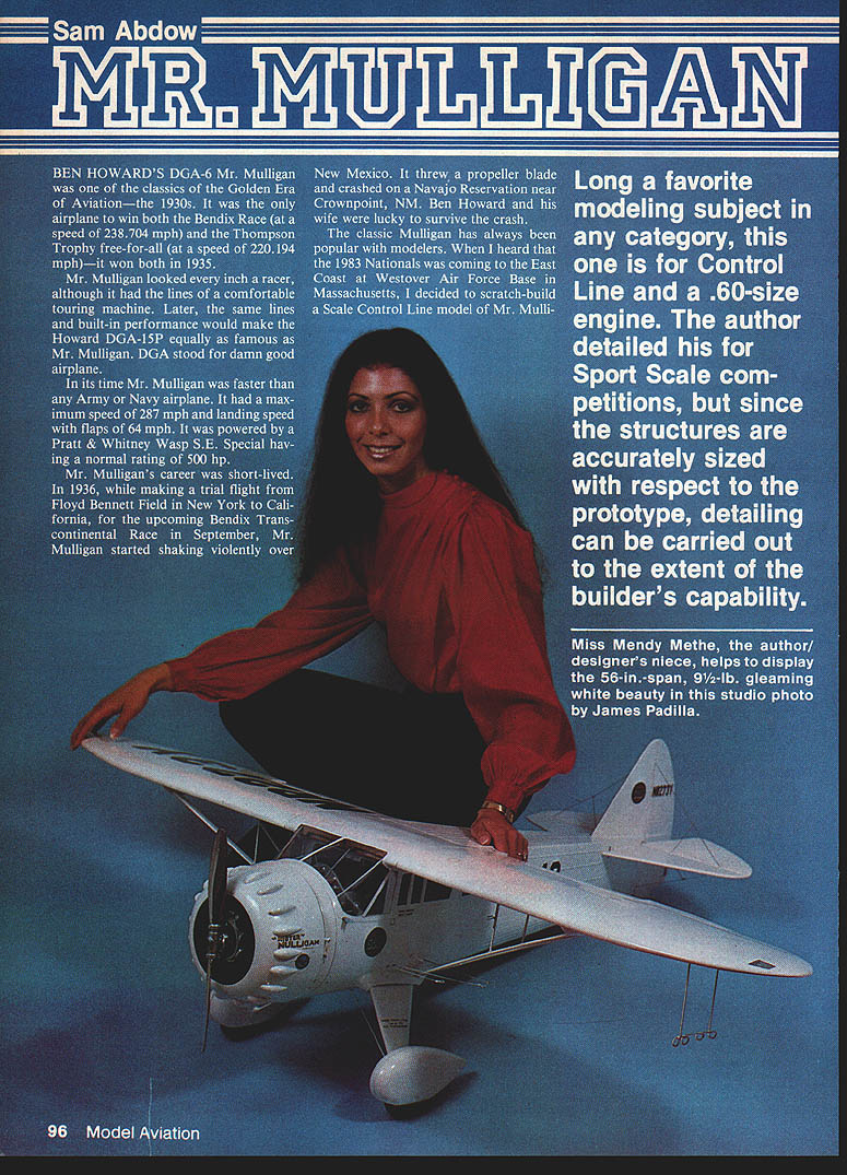
Long a favorite modeling subject in any category, this one is for control-line and a .60-size engine. The structures are accurately sized with respect to the prototype, so detailing can be carried out to the extent of the builder's capability.
I used Historical Aviation Album's drawings and enlarged a set of plans to a scale of 1¼ in. to 1 ft. so it would comfortably house a .50-size engine within the cowl. If you intend to enter competition, obtain the documentation-type drawings from Historical Aviation Album, P.O. Box 33, Temple City, CA 91780 (Howard DGA-6 Mr. Mulligan, three sheets, No. 14-99A).
I drew my plans to exact scale, so they could be used for either Precision Scale or Sport Scale. I chose Sport Scale because I planned to enter my Howard DGA-15P in Precision Scale. I started building Mulligan in January 1983 and, being retired and able to work every day, completed it in May of the same year. It is not a project for beginners.
For those who wish to do so, this Mr. Mulligan could be converted easily to radio control (RC).
My model weighs 9½ lb, including 16 oz. of lead I had to add in the cowl to balance the airplane properly. When you build yours, build the tail light to avoid the need for so much lead.
At the 1983 Nats my Mr. Mulligan placed fourth in Open CL Sport Scale, missing third place by one point. My Howard DGA-15P placed second in Open CL Precision Scale. In September 1983, Mr. Mulligan placed second at a Flushing Meadow Park (NY) meet.
Before beginning construction, study the plans thoroughly and take your time. Pre-kit the model as much as possible. Build the fuselage first, since it is the most important construction phase.
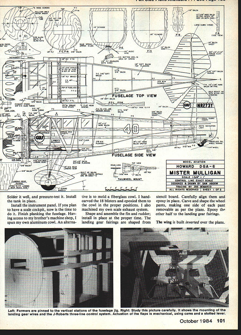
JIG AND FUSELAGE
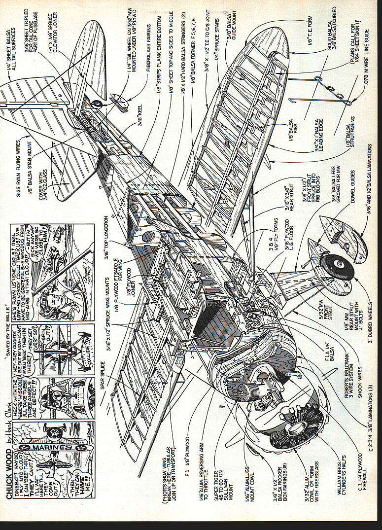
The fuselage is an assembly of a keel, crutch, and formers, so first construct a simple jig:
- Use 3/4-in. pine stock; select nice straight pieces.
- Base dimensions: 36 in. long by 6 in. wide.
- Draw a centerline down the middle of the base.
- Screw vertical pieces to the base at the proper locations to hold the formers for insertion of the 1/4 x 1/2-in. crutch pieces.
- Draw a centerline on the top and front side of each station to keep formers true.
- Draw centerlines on Formers F-1 to F-8.
Begin building the fuselage:
- Glue F-1 to F-1A. When dry, pin this to the front side of Sta. F-1.
- Pin F-2 through F-9 on centerlines and fronts of all stations.
- Glue the 1/4 x 1/2-in. balsa crutches to the formers, then glue KT-1, KT-4, and TC.
- Glue FT-L and FT-R to the notches in the top sides of the formers from F-2 to F-8.
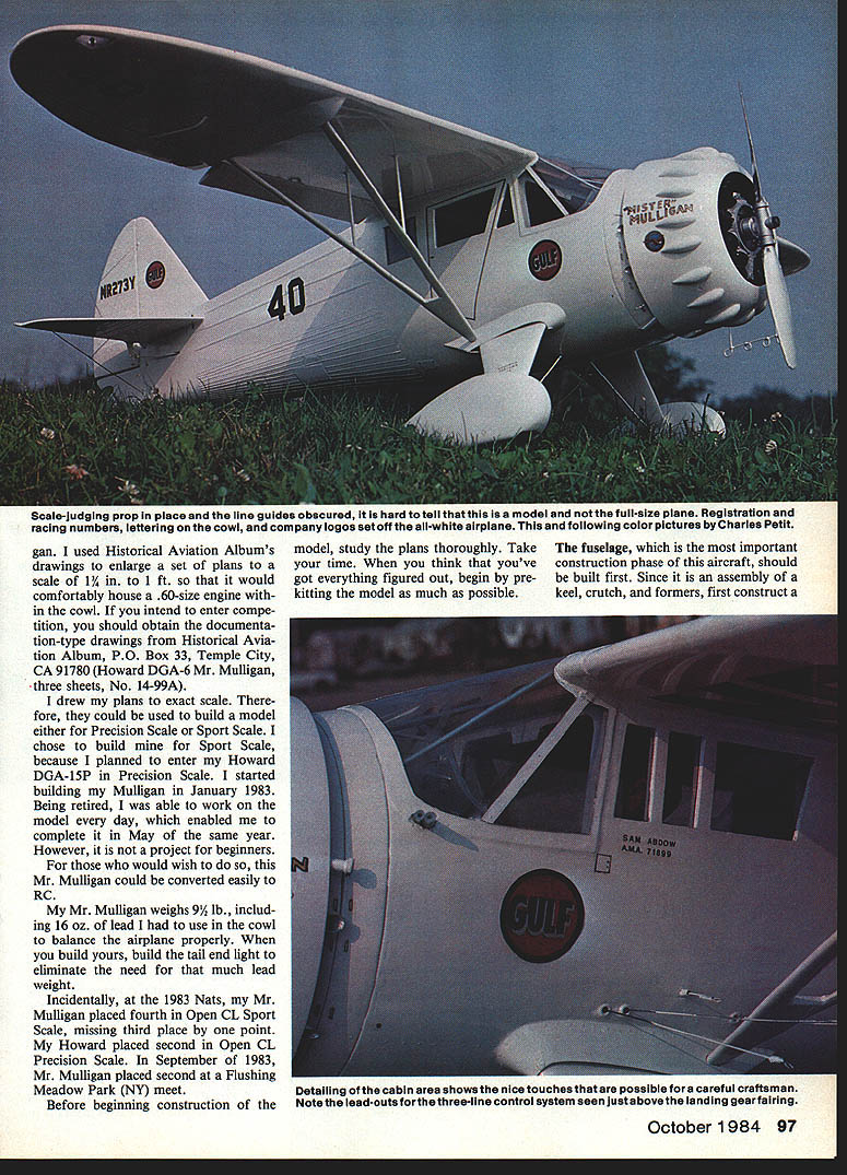
Note: lead-outs for the three-line control system are located just above the landing gear fairing.
Detailing the cabin area allows some nice touches by a careful craftsman. When the assembly is dry, remove it from the jig and glue the lower keel to the fuselage.
LANDING GEAR, CABIN, ENGINE, AND CONTROLS
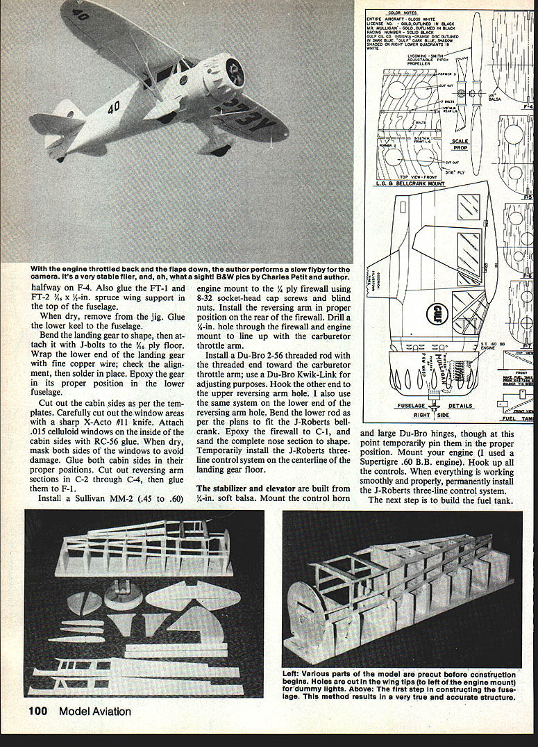
Bend the landing gear to shape and attach it with J-bolts to the 3/16-in. ply floor. Wrap the lower end of the landing gear with fine copper wire, check the alignment, then solder in place. Epoxy the gear in its proper position in the lower fuselage.
Cut out the cabin sides per the templates. Carefully cut the window areas with a sharp X-Acto #11 knife. Attach .015-in. celluloid windows on the inside of the cabin sides with carpenter's glue and RC-56 glue. When dry, mask both sides of the windows to avoid damage, then glue both cabin sides in position. Cut out reversing-arm sections in C-2 through C-4, then glue them to F-1.
Install a Sullivan MM-2 (.45 to .60) engine mount to the 1/4-in. ply firewall using 8-32 socket-head cap screws and blind nuts. Install the reversing arm on the rear of the firewall. Drill a 1/4-in. hole through the firewall and engine mount to line up with the carburetor throttle arm.
Install a Du-Bro 2-56 threaded rod with the threaded end toward the carburetor throttle arm; use a Du-Bro Kwik-Link for adjustment. Hook the other end to the upper reversing-arm hole. Use the same system on the lower reversing-arm hole. Bend the lower rod as per the plans to fit the J-Roberts bellcrank. Epoxy the firewall to C-1 and sand the complete nose section to shape. Temporarily install the J-Roberts three-line control system on the centerline of the landing gear floor.
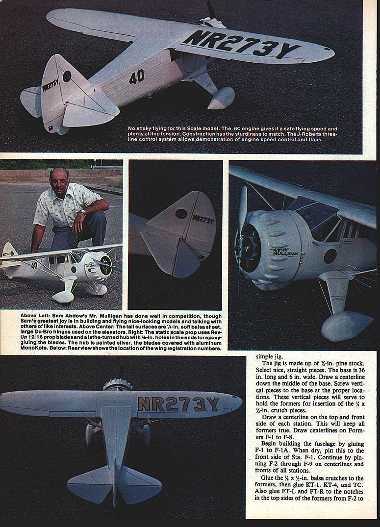
The stabilizer and elevator are built from 1/4-in. soft balsa. Mount the control horn and large Du-Bro hinges; temporarily pin them in position. Mount your engine (I used a Super Tigre .60 B.B. engine) and hook up all controls. When everything works smoothly, permanently install the J-Roberts three-line control system.
FUEL TANK, COCKPIT, COWL, AND EXHAUST
Build the fuel tank, solder it well, pressure-test it, and install it in place.
Install the instrument panel. If you plan to have a scale cockpit, do it now. Finish planking the fuselage.
Having access to my brother's machine shop, I spun my own aluminum cowl. An alternative is a molded fiberglass cowl. I hand-carved the 18 blisters and epoxied them to the cowl in the proper positions. I also machined my own scale exhaust system.
Shape and assemble the fin and rudder and install them at the proper time. The landing gear fairings are shaped from stencil board—carefully align and epoxy them in place. Carve and shape the wheel pants, making one side of each pant removable per the plans; epoxy the other half to the landing gear fairings.
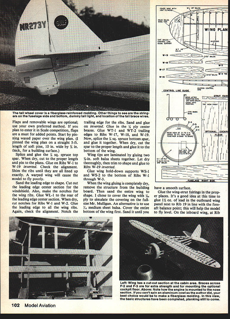
WING CONSTRUCTION
The wing is built inverted over the plans. Flaps and removable wings are optional, but flaps are essential for Scale competition to gain added points. Start by pinning waxed paper over the wing plan. (I pinned the wing plan on a straight 5-ft length of soft pine, 10 in. wide by 3/4 in. thick, as a building surface.)
- Splice and glue the 1/4-in. square spruce top spar. When dry, cut to the proper length and pin to the plans.
- Glue on Ribs W-1 to W-19 inverted. Check alignment and shim the ribs until they are all exactly lined up—a warped wing will fly poorly.
- Sand the leading edge to shape. Cut out the leading-edge center section for the windshield and make notches for the wing ribs.
- Glue WL-1 to the rear of the leading-edge center section. When dry, cut notches for Ribs W-1 and W-2. Glue the leading edge to all wing ribs and check alignment.
- Notch the trailing edge for the ribs, sand and glue it on inverted. Glue in the 1/4-in. ply center braces.
- Glue WT-1 and WT-2 trailing edges to Ribs W-17, W-18, and W-19.
- Splice the 1/4-in. square spruce bottom spar, glue it together, cut to length, and glue it to the bottom of the wing.
Wing tips are laminated by gluing two 1/8-in. soft balsa sheets together. Let dry thoroughly, trim to shape, and glue to Ribs W-19 inverted.
Glue wing hold-down supports WS-1 and WS-2 to the bottom of Ribs W-1 through W-3.
When the wing gluing is completely dry, remove the structure from the building board and sand the entire wing to shape. I chose to cover the wing with 1/64-in. plywood to simulate the covering on the full-size Mr. Mulligan. An alternative is 1/16-in. medium sheet balsa. Cover the entire bottom of the wing first and sand until smooth.
Glue the wing-strut fairings in place. It is a good idea to glue 1/2 oz. of lead in the outboard wing panel next to Rib W-19 in line with the fore-aft balance point to help the model fly level.
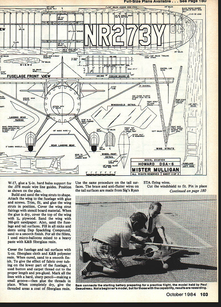
At W-17, glue a 3/4-in. hard balsa support for the .078 music-wire line guides; position as shown on the plan.
Build and sand the wing struts to shape. Attach the wing to the fuselage with glue and screws. Trim, fit, and glue the wing struts in position and cover the wing-strut fairings with stencil board. When the glue is dry, cover the top of the wing with 1/64-in. plywood and sand the wing with 360-grit sandpaper.
Also sand the fuselage and tail surfaces. Fill all nicks and dents using Dap Spackling Compound and sand to a smooth finish. For fillets, I used micro-balloons mixed to a heavy paste with K&B fiberglass resin.
COVERING, THREADING, AND FINAL ASSEMBLY
Cover the fuselage and tail surfaces with 1/2-oz. fiberglass cloth and K&B polyester resin. When cured, sand to a smooth finish.
To give the effect of fabric over tubing on the lower part of the fuselage, I used button and carpet thread cut to the proper length and pre-glued. Mark all the lines with a hard, sharp pencil—making a small groove—then glue the threads in place. When completely dry, give the threaded areas a coat of fiberglass resin. Use the same procedure on the tail surfaces.
The brace and anti-flutter wires on the tail surfaces are made from Sig's Ryan STA flying wires.
Cut the windshield to fit, pin it in place, and adhere it with RC-56 glue.
FINISHING
- Prime the model with Martin Senour Lacquer Primer, light gray #7865. Let dry 24 to 36 hours, then sand with 400-grit paper.
- Paint the model with Pactra Formula-U Polar White. Let it dry thoroughly for at least 72 hours.
Markings and trim:
- The black racing numbers were cut from a Sig black decal sheet.
- The gold registration numbers were cut from gold Trimline MonoKote.
- For black trim around the wing registration numbers, I used Goldenberg 1/8-in. striping tape.
- I painted the black trim around the rudder registration numbers with Formula-U and painted "Mr. Mulligan" on the cowl with gold leaf.
Pratt & Whitney and sponsor logos:
- The Pratt & Whitney logo used in the 1936 racing season was made from a colored logo in a Pratt & Whitney brochure. I photographed it to size with a 35mm camera on a tripod, cut out the picture with an X-Acto No. 11 blade, peeled off the back side of the photo emulsion, pushed the emulsion with a pointed toothpick, then attached it to the cowl with RC-56 glue.
- I used the same procedure to make the Gulf emblems on the fuselage and rudder using a Gulf decal from an old Sterling kit. When dry, cover the logos (only) with Formula-U clear.
Even weighing 9½ lb, my Mr. Mulligan is an excellent flier.
Transcribed from original scans by AI. Minor OCR errors may remain.

