
Mr. Spook III
George H. Clapp
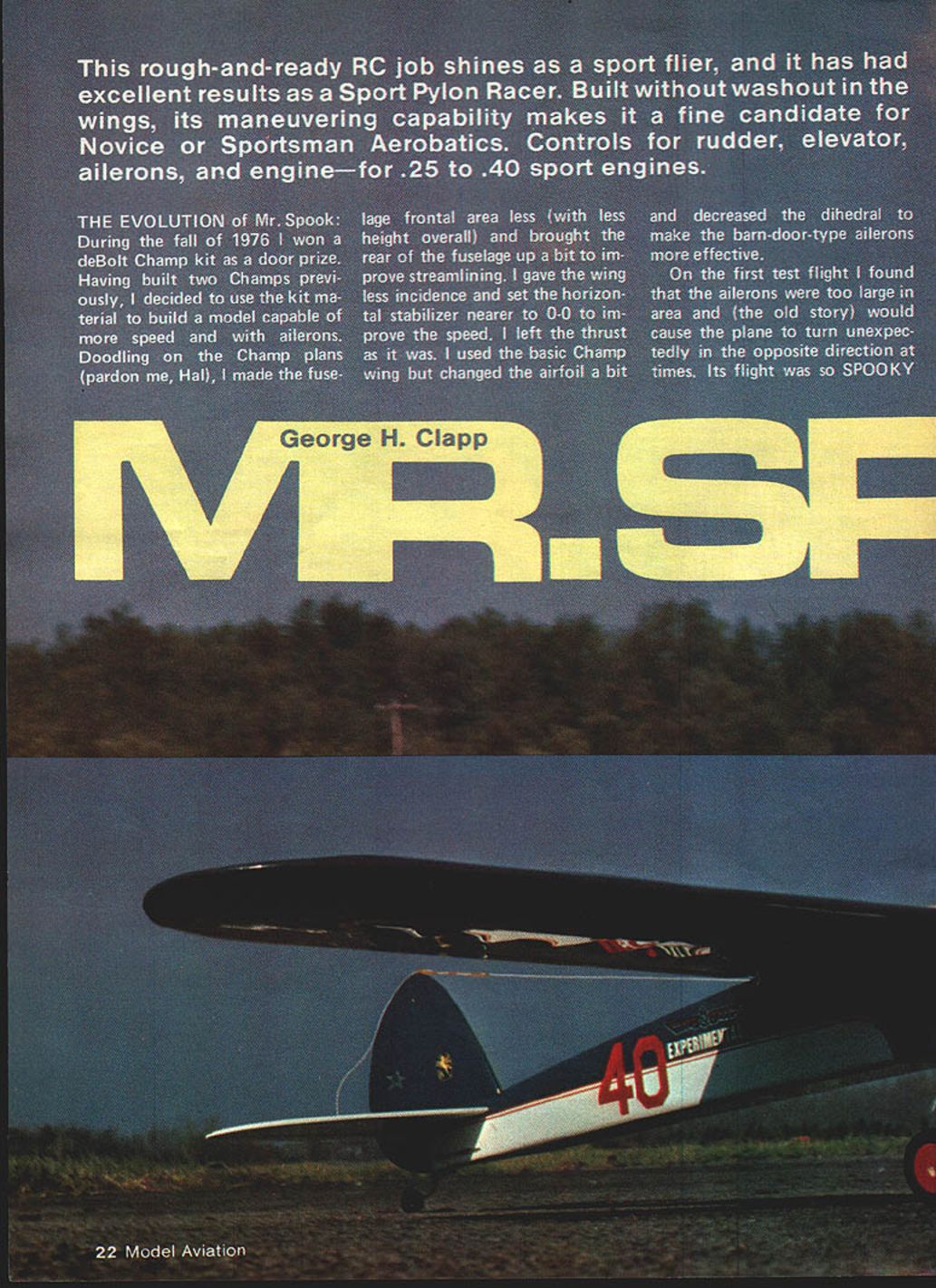
This rough-and-ready RC job shines as a sport flier, and it has had excellent results as a Sport Pylon Racer. Built with two degrees of washout in the wings, its maneuvering capability makes it a fine candidate for Novice or Sportsman Aerobatics. Controls for rudder, elevator, ailerons, and engine—for .25 to .40 sport engines.
THE EVOLUTION of Mr. Spook
During the fall of 1976 I won a deBolt Champ kit as a door prize. Having built two Champs previously, I decided to use the kit material to build a model capable of more speed and with ailerons. Doodling on the Champ plans (pardon me, Hal), I reduced the fuselage frontal area (less height overall) and brought the rear of the fuselage up a bit to improve streamlining. I gave the wing less incidence and set the horizontal stabilizer nearer to 0-0 to improve speed. I left the thrust as it was. I used the basic Champ wing but changed the airfoil a bit and decreased the dihedral to make the barn-door-type ailerons more effective.
On the first test flight I found that the ailerons were too large in area and (the old story) would cause the plane to turn unexpectedly in the opposite direction at times. Its flight was so spooky that I shelved it until sometime later.
In 1979 the Syracuse Thunderbird Aero Radio Society began a season of Sport Pylon Racing, and I used my 1936 Old-Timer design, Torc, which was published as a trainer in Model Builder in 1978. I entered it in Novice to get some experience in rounding the pylons. When the third race came up Torc was under repair, and the only airplane I had in one piece was the outgrowth of the Champ kit. I knew what was wrong with it and reasoned that if Frise-type ailerons had solved the same problem on real aircraft during the late 1920s, I would try something like it. (The leading edge of a Frise-type aileron projects below the wing when in the up position to produce the needed drag to offset the other down aileron.) There wasn't time to rebuild the wing with Frise-type ailerons, so I decided to modify the existing ailerons to equalize the lateral drag.
I did this by installing small inverted airfoils below each aileron with a gap to allow the airflow to go between. When the aileron went up, the leading edge of this small airfoil came down farther in the slipstream to equalize the aileron drag. I call these added airfoils "collectors." I had time to test Mr. Spook before the next race. The collectors worked very well: the roll rate was fairly fast, and with the decreased incidence in the wing the plane was much faster than a regular Champ. I finished out the '79 racing season with this bird, and everyone who saw it asked, "What are those gizmos below the ailerons?"
During the next winter I rebuilt it to try for more speed. I added 4 in. to the rear of the fuselage for better ground control, and I designed a new wing with a symmetrical airfoil and rounded wing tips.
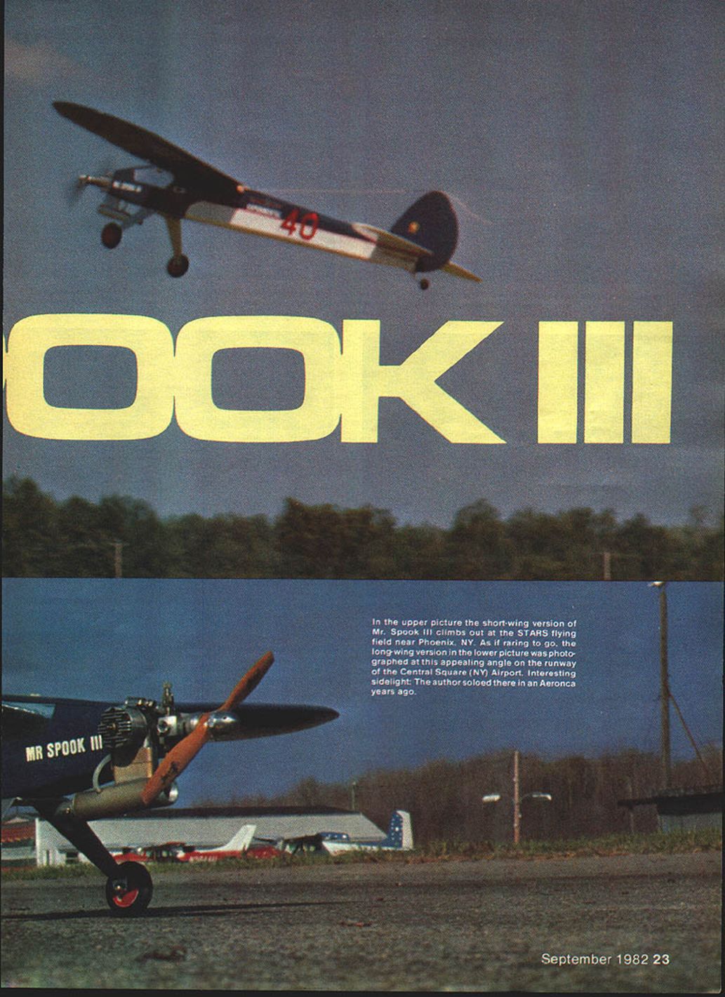
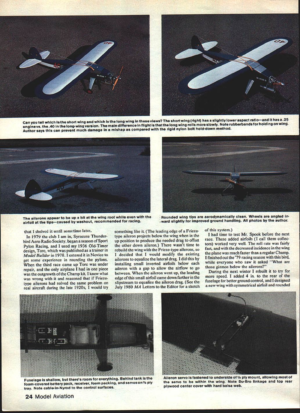
I experimented with short- and long-wing versions. The short wing has a slightly lower aspect ratio and used a .25 engine versus the .40 used on the long-wing version. The main difference in flight is that the long wing rolls more slowly. Rounded wingtips are aerodynamically clean, and wheels angled outward slightly improve ground handling.
Mr. Spook II (1.5-500 class, Enya .40) flew the 1980 racing season but could never get close enough to the pylons to win. It was a great flier but much too large and heavy for racing; it was trimmed out at too great an angle of attack and its weight slowed it down. Early in the spring of 1981 I designed an entirely new Mr. Spook III to incorporate the best features of the two former aircraft.
First, I built a very strong, rubber-band-mounted wing that could slide forward in the event of a hard landing. I set out to build a tough craft that was also light. The shock-mounted wing arrangement proved to be a good compromise between appearance and durability. Wing-mounted rubber bands may look nice mounted on nylon bolts, but in a mishap the shock-mounted wing can take the impact of a hard landing and prevent much damage compared with a rigid nylon-bolt hold-down method.
I had an O.S. .25 Schnuerle engine on hand and decided to build the plane for it — with a shorter wing. In this configuration it meets the AMA Sport Pylon rules (minimum of 450 sq. in. for a .29 — now 450 for a .35). This shorter wing has 453 sq. in. I finished the model in time to take it to Toledo in hopes of helping the Sport Pylon cause. Those of us who raced during these last few years have found that our skill at RC flying had been greatly improved. It's too bad that a lot of fliers feel they aren't good enough pilots to try Sport Pylon Racing. It's an excellent entry point, and it's not as tough as you may think.
Mr. Spook III, as it has evolved, is a great flier whether for Sport Pylon or just for sport. The plans are for the 15-500 version (15% airfoil thickness and 500 sq. in. wing area), but by removing one bay from each wing panel you have the shorter wing suitable for smaller engines. I flew the short-wing version in the 1981 racing season with an O.S. .25 Schnuerle engine.
After the racing season had ended, I built the longer 15-500 wing for it and changed to the Enya .40. There was very little difference in the flight characteristics with the bigger wing except that rolls were a bit slower. It is competitive with anything in Sport Pylon Racing.
Construction
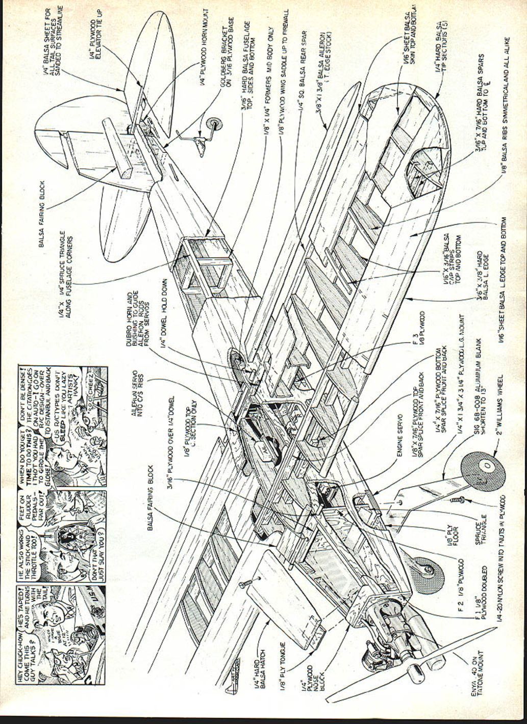
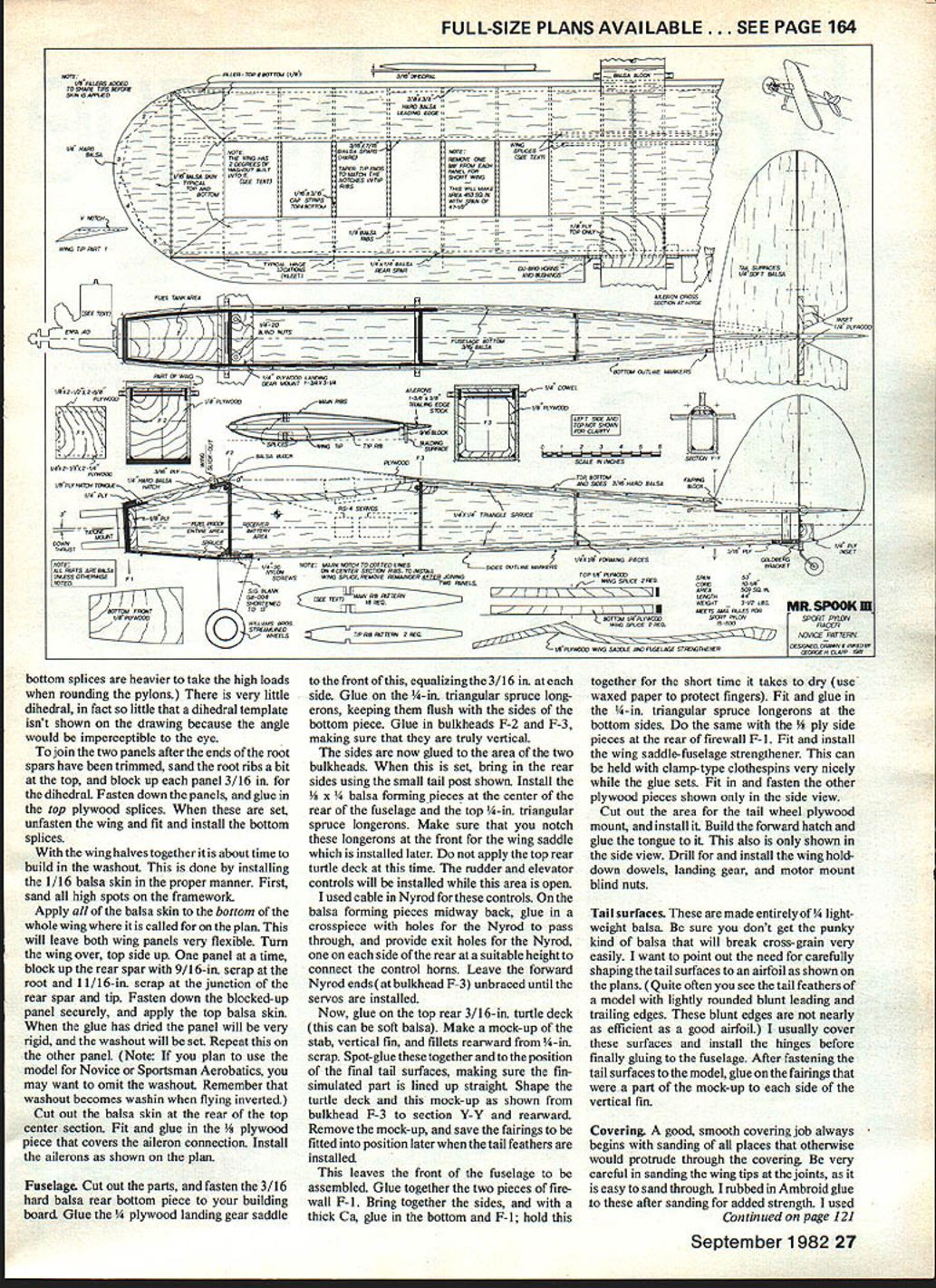
Study the plans and read these construction pointers. If you plan to change engines, I suggest that you use a Fox mount for each engine. By drilling both mounts the same (Fox mounts aren't pre-drilled), switching engines is no problem. All plywood is aircraft grade. Select strong balsa where strength is needed and lightweight balsa where it isn't.
Wing
Build the wing first, as it will be needed to fit the wing saddle on the fuselage. Cut out the ribs. All are identical with the exception of the two tip ribs. I suggest making an aluminum template as a guide for cutting the ribs.
- Cut the 3/16 x 7/16 hard balsa main spars a bit long (excess to be left at the root), and taper the tip ends to fit the 3/16 sq. notch at the smaller tip ribs.
- Also cut a bit long the 1/4 sq. hard balsa rear spars and the 3/8 sq. hard balsa leading edge.
- Cut out parts 1, 2, 3, 4, and 5 of the wing tips, and glue them together over the plan, using waxed paper to protect the plan. Let dry thoroughly.
Make one wing panel at a time over the plan on a flat building board. Both the right and left panels are the same at first because of the symmetrical airfoil.
- Pin the bottom main spar down securely. Take the 1/4 sq. rear spar and block it up with 9/16 scrap pieces. Pin everything securely to the building board.
- Try out all the ribs to make sure they fit, then glue in place. Leave pinned down, and install the top main spar.
- Fit and glue on the 3/8 sq. leading edge, making sure it runs out past the small tip rib. I used Super Jet cyanoacrylate glue (CA) for most of the model; it makes a good joint and saves time.
At this point you will notice that the shorter tip rib has a gap between it and the leading edge. This is filled in with the wing tip. Take the assembled tip and cut or file a V in it to fit the leading edge. Fit the rear where it joins the rear spar, block it up with 9/16 scrap pieces, and glue to the wing. Let the glue dry thoroughly before removing the panel from the board. Glue in the 1/8 balsa fillers at the leading edge of the tips, both top and bottom — these prevent sanding through the final skin.
Repeat this process for the other panel. At this point, remember, there is no right or left. When both wing panels are finished, mark and cut out the notches on the center section ribs to accept the plywood wing splices. This will make the panels right and left.
Cut out the wing splices from 1/4 and 1/8 aircraft plywood. The 1/8-in. splices go on top and the 1/4-in. splices on the bottom.
Fuselage
Cut out the parts, and fasten the 3/16 hard balsa rear bottom piece to your building board. Glue the 1/4 plywood landing gear saddle to the front of this, equalizing the 3/16 in. at each side. Glue on the 1/16-in. triangular spruce longerons, keeping them flush with the sides of the bottom piece. Glue in bulkheads F-2 and F-3, making sure that they are truly vertical.
The sides are now glued to the area of the two bulkheads. When this is set, bring in the rear sides using the small tail post shown. Install the 1/4 balsa forming pieces at the center of the rear of the fuselage and the top 1/4-in. triangular spruce longerons. Make sure that you notch these longerons at the front for the wing saddle which is installed later. Do not apply the top rear turtledeck at this time. The rudder and elevator controls will be installed while this area is open.
I used cable-in Nyrod for these controls. On the balsa forming pieces midway back, glue in a crosspiece with holes for the Nyrod to pass through, and provide exit holes for the Nyrod on each side of the rear at a suitable height to connect the control horns. Leave the forward Nyrod ends (at bulkhead F-3) unbent until the servos are installed.
Now glue on the top rear 3/16-in. turtledeck (this can be soft balsa). Make a mock-up of the stab, vertical fin, and fillets rearward from 1/8-in. scrap. Spit-glue these together and to the position of the final tail surfaces, making sure the fin-stab unit is lined up straight. Shape the turtledeck and this mock-up as shown from bulkhead F-3 to section Y-Y and rearward. Remove the mock-up, and save the fairings to be fitted into position later when the tail feathers are installed.
This leaves the front of the fuselage to be assembled. Glue together the two pieces of firewall F-1. Bring together the sides, and with a thick CA, glue in the bottom and F-1; hold this together for the short time it takes to dry (use waxed paper to protect fingers). Fit and glue in the 1/4-in. triangular spruce longerons at the bottom sides. Do the same with the 1/8 ply side pieces at the rear of firewall F-1. Fit and install the wing-saddle-fuselage strengthener; this can be held with clamp-type clothespins while the glue sets. Fit in and fasten the other plywood pieces shown only in the side view. Cut out the area for the tail wheel plywood mount, and install it. Build the forward hatch and glue the tongue to it. Drill for and install the wing hold-down dowels, landing gear, and motor mount blind nuts.
Tail surfaces
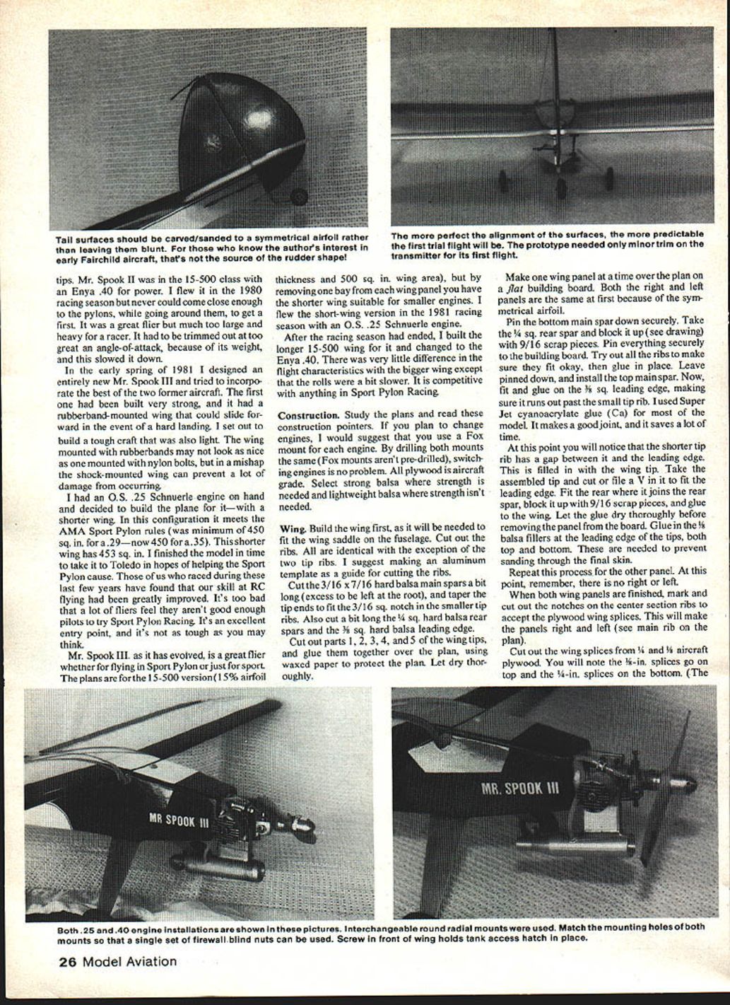
These are made entirely of 1/8 light-weight balsa. Be sure you don't get the punky kind of balsa that will break cross-grain very easily. Carefully shape the tail surfaces to an airfoil as shown on the plans. Often you see tail feathers with lightly rounded blunt leading and trailing edges; these blunt edges are not nearly as efficient as a good airfoil. I usually cover the tail surfaces and install the hinges before finally gluing them to the fuselage. After fastening the tail surfaces to the model, glue on the fairings that serve as part of the mock-up to each side of the vertical fin.
Covering
A good, smooth covering job always begins with sanding off all places that otherwise would protrude through the covering. Be very careful in sanding the wing tips at the joints, as it is easy to sand through. I rubbed in Ambroid glue to these after sanding for added strength. I used Super MonoKote covering film.
Balance
The center of balance (let's not call it center of gravity) should be as shown on the plans for racing. For better aerobatics in Novice or Sportsman Pattern, the balance point can be a bit farther aft. Be sure to balance the wing after it is covered. Even if balsa of the same density is used, very seldom are both sides the same weight. On the large wing I built, a #10 common nail was needed to bring it into balance. If your wing needs balancing, drill a small hole in the extreme tip for a nail and glue it with a CA.
With the model not in perfect balance (nose- or tail-heavy) it may be trimmed in flight and left that way without trying to balance it to perfection. In this condition the aircraft will only be in trim at the velocity it was flying when it was trimmed. At a higher or lower velocity the amount of pressure on the trimmed elevator will vary and cause the need for excessive control stick manipulation to counteract it. Of course, the farther out of balance the aircraft is, and the more elevator that is used for trim, the worse this condition becomes.
There are many other forces that can be involved, but in an aircraft like Mr. Spook III — with 0-0 incidence and with the amount of down-thrust used — knowledge of these out-of-trim characteristics can help you get it in perfect balance longitudinally. Lateral balance is taken care of primarily by balancing the wing.
Flying
This model has given me many pleasurable hours of flying both in Pylon Racing and fun flying, and it doesn't seem to have any bad traits. The ailerons with either wing are super-sensitive. When first test flying the plane, I advise setting aileron throws at the minimum. Rolls with the small wing are much faster than with the long wing because of less area to rotate. Either way, it shows no tendency to tip stall on takeoff, even when pulled up sharply. This can be credited to the two degrees of washout. It can be brought in for landing in a three-point attitude (all the way) using a little back pressure on the stick; this minimizes the more usual extended glide at flare-out. Anyone with aileron experience will feel at ease flying Mr. Spook III.
Propeller Tests
Static tests of different props on an O.S. .25FSR with 15% nitro fuel. All props are wood unless noted. Static tests were conducted with the engine mounted in Mr. Spook III.
- 7x6 Top Flite (racing) — 16,500 rpm — 2 1/4 lb. thrust
- 8x4 Zinger — 16,500 rpm — 3 1/4 lb. thrust
- 8x5 Zinger — 15,000 rpm — 3 1/8 lb. thrust
- 8x6 Zinger — 14,000 rpm — 2 3/4 lb. thrust
- 8x6 Tornado (nylon) — 14,000 rpm — 2 3/4 lb. thrust
- 8x7 Zinger — 13,500 rpm — 2 3/4 lb. thrust
- 8x8 Top Flite (racing) — 13,000 rpm — 3 1/4 lb. thrust
- 9x4 Zinger — 13,500 rpm — 3 1/4 lb. thrust
- 9x5 Zinger — 12,500 rpm — 3 1/2 lb. thrust
- 9x6 Zinger — 12,000 rpm — 3 1/2 lb. thrust
- 9x7 Zinger — 11,000–12,000 rpm — ~3 lb. thrust
- 9x7 Zinger (other sample) — 14,000 rpm — ~2 1/2 lb. thrust
Taking into account that rpm will increase with the model moving through the air in flight (because the load on the prop lessens), it is wise to select a prop that allows higher pitch to be used to advantage with the increase in rpm. The best combination of pitch, rpm, diameter, and thrust seems to be with the 9‑inch diameter group. With the 8x6 and 9x6 Zinger, note that 2,000 rpm is lost with the 9x6, but the thrust is improved.
Construction materials list and notes
- 4-ply servo bushing to guide into center-section ribs
- Aileron rods
- Balsa fairing block from servos
- 3/16 ply wood over 1/4 dowel
- 1/4 plywood horn mount
- Goldberg bracket on 3/16 ply wood base
- 3/16 hard balsa fuselage top, sides and bottom
- Balsa hatch
- 1/4 x 1/4 formers mid-body only
- 1/8 ply tongue
- 1/8 ply wing saddle up to firewall
- 1/4 sq. balsa rear spar
- Nose 8 x 3/8 balsa
- Aileron trailing-edge stock
- Engine servo
- 1/16 sheet balsa skin top and bottom
- 1/8 x 7/16 plywood top front spar splice
- Front and back 1/4 hard balsa spar
- Spruce front and back engine mount strips
- 1/4 x 3/4 x 3/4 ply engine mount top and bottom
- 1/8 spruce firewall
- Aluminum blank engine mount
- 3/16 and 7/16 hard balsa spars
- Ply double triangle mount
- Wheel 1/16 sheet balsa edge top and bottom
- 1/8 balsa ribs symmetrical and all alike
Have fun.
Transcribed from original scans by AI. Minor OCR errors may remain.

