
Mud Duck
Tom Chipley
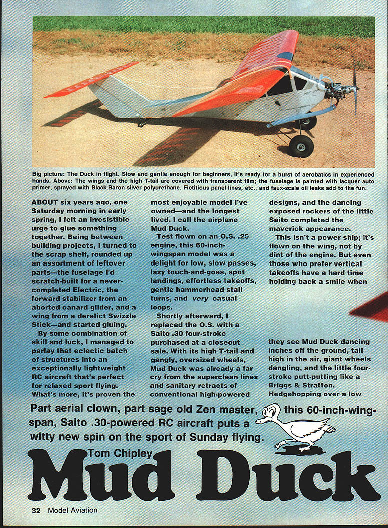
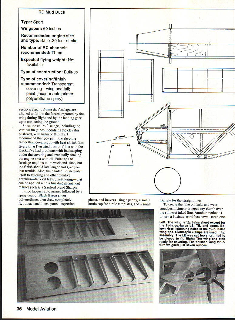
Part aerial clown, part sage old Zen master, this 60-inch wingspan, Saito .30–powered RC aircraft puts a witty new spin on the sport of Sunday flying.
About six years ago, one Saturday morning in early spring, I felt an irresistible urge to glue something together. Between projects, I turned to the scrap shelf, rounded up an assortment of leftover parts—the fuselage I'd scratch-built for a never-completed electric project, the forward stabilizer from an aborted canard glider, and a wing from a derelict Swizzle Stick—and started gluing. By some combination of skill and luck, I parlayed that batch of structures into an exceptionally lightweight RC airplane that's perfect for relaxed sport flying. I call the airplane Mud Duck.
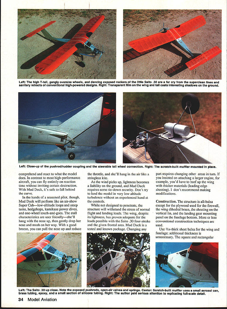
Test flown initially on an O.S. .25, this 60-inch-wingspan model was delightful for low, slow passes, lazy touch-and-goes, spot landings, effortless takeoffs, gentle hammerhead stall turns, and very casual loops. I later installed a Saito .30 four-stroke purchased at a closeout sale; its exposed rockers and the Duck's high T-tail and gangly oversized wheels completed the maverick appearance.
Flight characteristics
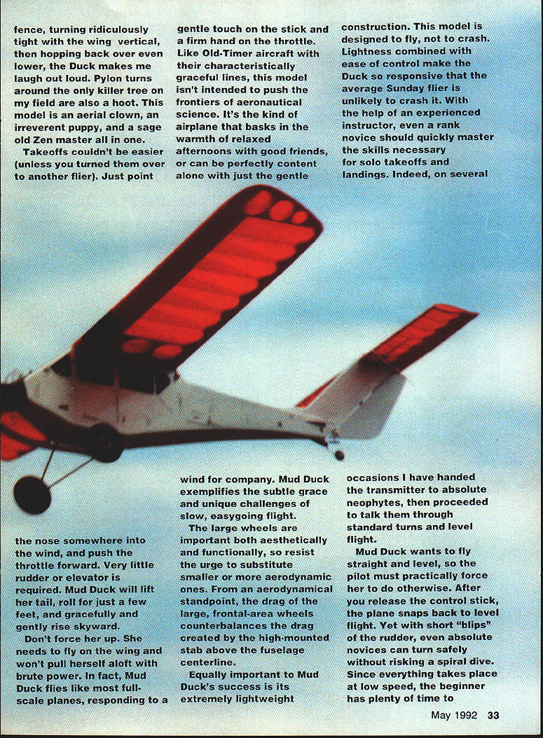
- Mud Duck is flown on the wing rather than by brute engine power. It needs a gentle touch on the stick and a firm hand on the throttle.
- It is forgiving and beginner-friendly: the plane tends to fly straight and level and will snap back toward level when controls are released. Short rudder blips produce safe turns without risking a spiral dive.
- Stall behavior is benign: the model will hang nose-up, then gently drop the nose and mush in. In a good breeze it can pull the nose up and hang like a stringless kite with reduced throttle.
- In the hands of a seasoned pilot it will perform spirited maneuvers—low-altitude loops, steep turns, hedgehops, kamikaze power dives, and one-wheel touch-and-goes. Pylon turns and tight fence-hops are a hoot; the Duck makes me laugh out loud.
- Takeoffs are simple: point into the wind and advance throttle. Very little rudder or elevator is required. Don’t force her up—she needs to fly on the wing.
- As wind picks up, the Duck’s extreme lightness becomes a liability on the ground. Use tie-downs and avoid very low landings in turbulent air.
- The tested, known power package is the Saito .30 four-stroke. If you insist on a larger engine, you must beef up the wing (thicker materials and leading-edge sheeting); I do not recommend modifications.
Construction
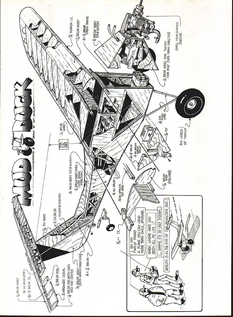
The structure is all balsa except where plywood is used: firewall, wing dihedral brace, some sheeting, the vertical fin sheeting, the landing-gear mounting panel, and the fuselage bottom. More-or-less conventional techniques are used with a few less-conventional choices to keep weight down and strength adequate.
Materials and general recommendations
- Use 1/16-inch sheet balsa for wing and fuselage sheeting; additional thickness is unnecessary.
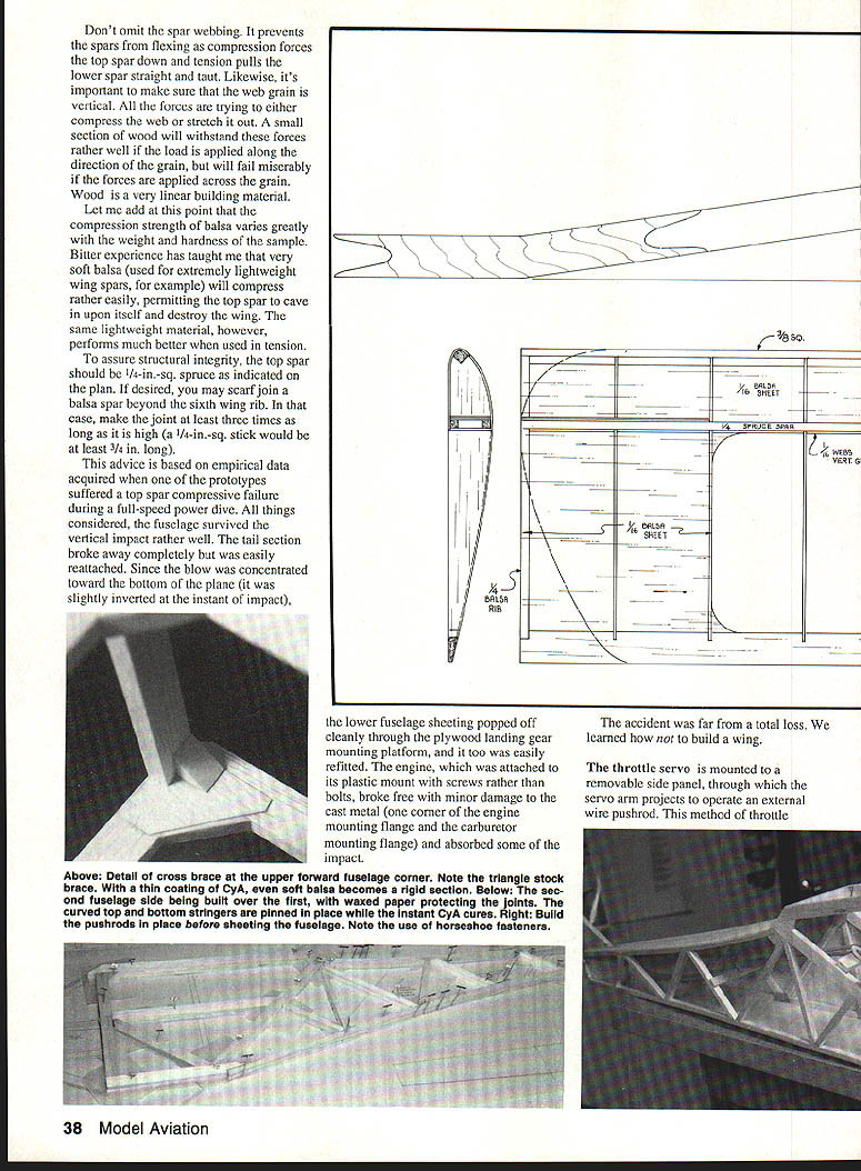
- The top spar should be 1/4-in.-sq. spruce as shown on the plan. If you scarf-join a balsa spar, make the joint at least three times as long as it is high.
- Sheet the entire fuselage, including the vertical fin (the elevator pushrod passes through it). Balsa/ply construction is recommended.
- Paint the sheeting rather than covering with heat-shrink film. Iron-on films on this airframe have allowed fuel seepage under the covering around the engine area; a painted finish is more fuelproof and accepts lettering and weathering.
- Adhesives:
- CyA (cyanoacrylate) is fine for many joints but requires neat, precise fits.
- Aliphatic resin is excellent for coating interior joint lines and for spar webbing where good coverage is needed.
- Five-minute epoxy is recommended for critical structural joins (stab/fin, firewall areas).
- After painting and weathering, spray on epoxy clear-coat in two parts for superior fuel proofing; many spray polyurethanes are not sufficiently fuelproof.
Sheeting, joints, and webbing
- The strength of a wood-to-wood joint relates directly to glued surface area. Reinforce joints with gussets, triangle stock, or corner fillers to get strength without excess weight.
- After attaching the wing leading-edge sheeting with slow-setting CyA, coat interior joint lines with aliphatic resin before attaching spar webbing. Use aliphatic for the webbing to assure full coverage.
- Do not omit the spar webbing. Webbing prevents the spars from flexing when compression loads push the top spar down and tension pulls the lower spar taut. Make sure the web grain is vertical so it handles compression/tension properly—wood is strong along the grain but weak across it.
- Beware of very soft balsa for compression parts; soft balsa can compress and let the top spar cave in. Use suitable hardness where loads demand it.
Fuselage
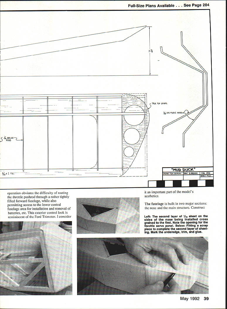
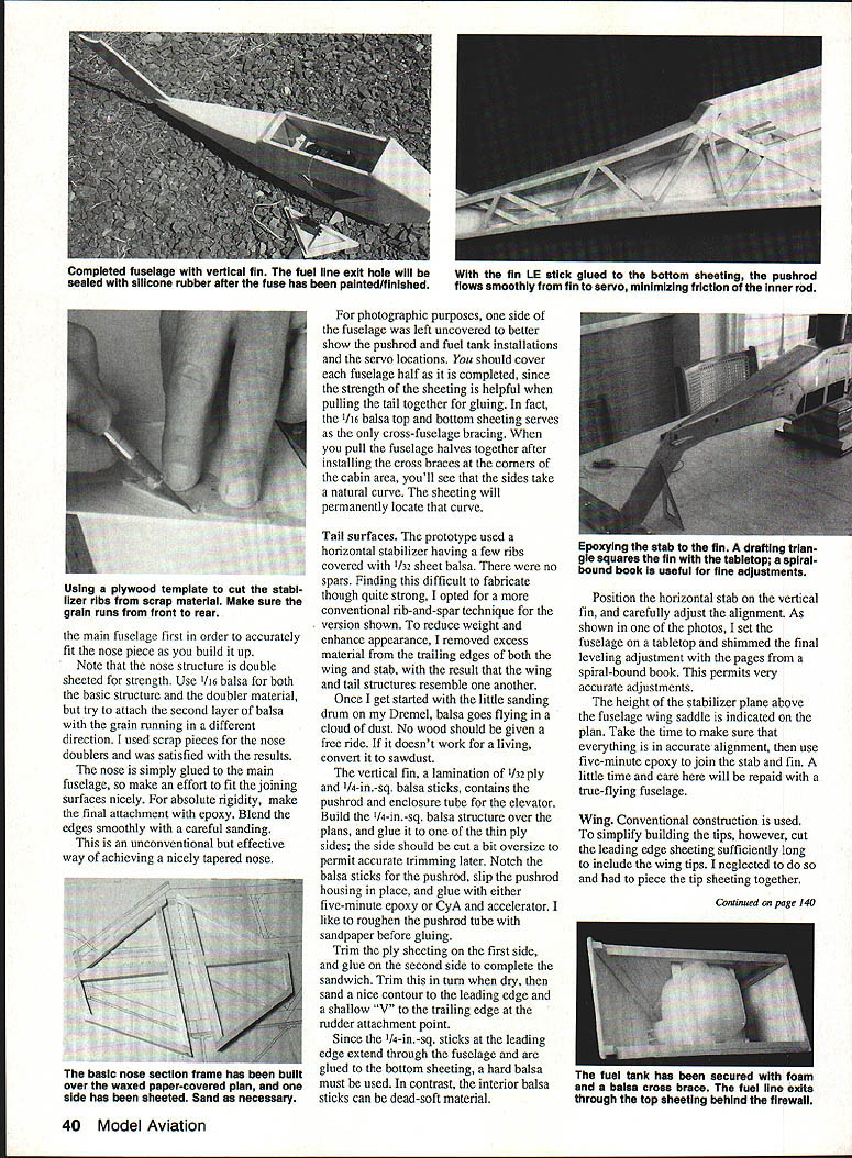
- The fuselage is built in two major sections: the nose and the main structure. Build each fuselage half and cover it as completed—the 1/16-inch balsa top and bottom sheeting serves as the only cross-fuselage bracing and establishes the side curve.
- For easier engine servicing and internal access, the throttle servo is mounted on a removable side panel, with the servo arm projecting to operate an external wire pushrod. This avoids routing the throttle pushrod through a crowded forward fuselage and gives a visually appealing external-control look.
- When joining the fuselage halves, install the cross braces at the cabin corners, then pull the halves together; the sheeting will locate the natural curve.
Tail surfaces
- The prototype used a stab with a few ribs covered in 1/32-sheet balsa and no spars. For ease of fabrication I opted for a conventional rib-and-spar stab on the shown version.
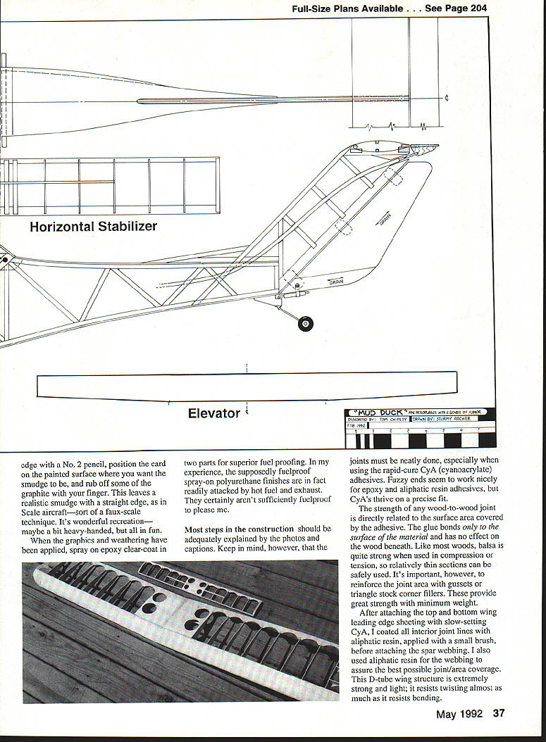
- The vertical fin is a lamination of 1/32 ply and 1/4-in.-sq. balsa sticks and contains the elevator pushrod tube. Build the balsa 1/4-in.-sq. structure over plans, glue it to one ply side, notch the sticks for the pushrod, slip in the pushrod housing, and secure with epoxy or CyA + accelerator. Roughen the pushrod tube with sandpaper before gluing for better adhesion.
- Trim the first ply side, glue on the second, then sand the leading edge contour and form a shallow "V" at the trailing edge where the rudder attaches.
- Position and align the horizontal stab on the fin carefully—use shims (pages of a spiral-bound book work well) to get accurate leveling. Use five-minute epoxy to join stab and fin.
Wing
- Conventional construction with a D-tube leading edge is used. Cut the leading-edge sheeting long enough to include the wing tips; piecing tip sheeting later is more trouble and looks unsightly through translucent covering.
- Vertical-grain balsa webs are glued to the outside trailing edge of the spars—easier than sandwiching them between spars. They may be slightly less compression-strong but adequate; do not omit them.
- Use hard trailing-edge stock for the wing and then remove excess material after assembly (I used a sanding drum). The finished wing is extremely light yet has stood up to the maximum stresses possible with the Saito .30.
- This D-tube wing structure is extremely strong and light; it resists twisting almost as much as bending.
Finishing and graphics
- I used lacquer auto primer followed by a spray coat of Black Baron silver polyurethane, then added fictitious panel lines, ports, inspection plates, and louvers with round and triangular templates.
- For faux oil leaks and wear smudges:
- Drag your thumb over still-wet inked lines, or
- Turn a business card face down, scrub one edge with a No. 2 pencil, position the card, and rub off graphite with your finger to leave a realistic straight-edged smudge.
- After graphics and weathering, seal with epoxy clear-coat in two parts for fuel resistance.
Structural anecdote and lessons
- One prototype suffered a top-spar compressive failure during a full-speed power dive. The fuselage survived the vertical impact reasonably well: the tail broke away and was easily reattached, lower fuselage sheeting popped off cleanly around the plywood landing gear mount and was refitted, and the engine mount screws let the engine break free with minor cast-metal damage and absorbed some impact. The accident taught us how not to build a wing and reinforced the importance of proper spar/webbing and compression-resistant materials.
- Mud Duck represents a balance of power, weight, and surface area. The structure and controls are designed to withstand normal flight and landing loads for the Saito .30/60-inch package.
Final notes
- The large, tall wheels are both aesthetic and functional; resist substituting smaller wheels. Their frontal-area drag complements the drag from the high-mounted stab and helps balance the airframe’s slow-speed handling.
- Keep joints neat and precise—fuzzy fits work for epoxy and aliphatic adhesives, but CyA needs precise mating surfaces.
- Use gussets and corner fillers to reinforce joints with minimal weight penalty.
- Mud Duck wants to fly straight and level; it rewards gentle stick inputs and patience. Flown as designed, it will provide many years of safe, enjoyable recreation. Happy landings!
Transcribed from original scans by AI. Minor OCR errors may remain.

