
The Mystique of the Flying Wing
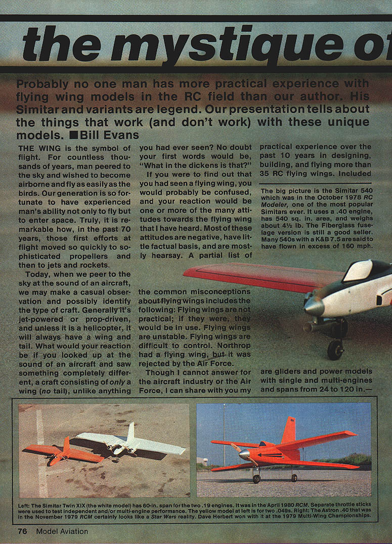
Probably no one man has more practical experience with flying wing models in the RC field than the author of this article. His Simitar family and variants are legendary. This presentation recounts what works (and what doesn't) with these unique models. — Bill Evans
Introduction
The wing is the symbol of flight. For countless thousands of years man has looked to the sky and wished to fly as easily as birds. In the past 70 years we moved from the first fragile aircraft to sophisticated propellers, jets, and rockets. Today we may casually identify most aircraft by sound or shape: jet or prop, with wings and a tail. What would your reaction be if you looked up and saw something consisting of only a wing — no tail — unlike anything you had seen before? The common reaction is confusion and many misconceptions.
Common misconceptions about flying wings include:
- Flying wings are not practical; if they were, they would be in use.
- Flying wings are unstable.
- Flying wings are difficult to control.
- Northrop had a flying wing, but it was rejected by the Air Force.
I cannot speak for the aircraft industry or the Air Force, but I can share my practical experience over more than ten years designing, building, and flying over 35 RC flying wings: gliders and powered models, single and multi-engine, spans from 24 to 120 inches.
How I Started
My flying wing work began as a personal challenge: to find how much truth there was in the negative comments. To evaluate fairly I had to design, build, and fly a flying wing.
My aircraft modeling experience began in the late 1930s (rubber and gas free flight, control line, and radio control). Early designs included the 1/2A Esquire, Silent Squire, and Slope Squire. The search for information before building led to three conclusions:
- Northrop's flight experience indicated flying wings could be practical (stable and maneuverable).
- French experiments pointed to the need for some reflex in the airfoil section.
- Other information showed the center of gravity (CG) needed to be located more forward than the conventional 1/3-chord location.
Using that guidance I planned my first flying wing project — a glider — because a powered craft might be too fast to control during initial learning.
Designing the First Wing (Saracen)
Sizing and planform
- Estimated flying weight: ~40 oz.
- Target wing loading: about 10 oz per sq. ft.
- Calculated required wing area: ~4.5 sq. ft.
- Planform chosen: tapered wing. Root chord 12 in, tip chord 6 in (1:2 taper) producing a 72 in span.
I avoided severe sweepbacks (which tend to fly nose-up and slide-turn, as with some deltas) and instead used a straight leading edge and a forward-tapering trailing edge.
Airfoil and construction
- Airfoil: semi-symmetrical section for a wide speed range with about 1% reflex (based on French data).
- A steep leading-edge entry was used to act as a turbulator.
- Wing cores were cut from foam using plywood templates (experience from Silent Squire and Slope Squire made this straightforward).
- Construction used partial sheeting of the foam.
- Instead of Northrop's split trailing-edge yaw control, I used a solid vertical fin (no rudder).
- A short fuselage (box) was required to hold radio components.
Controls: elevons and rigging
- Rather than separate inboard elevators and outboard ailerons (which presented linkage complexity), I used elevons to function as both elevators and ailerons.
- Rigging elevons so both surfaces can travel together or differentially is tricky. Some sliding servo systems with grooved rails bind.
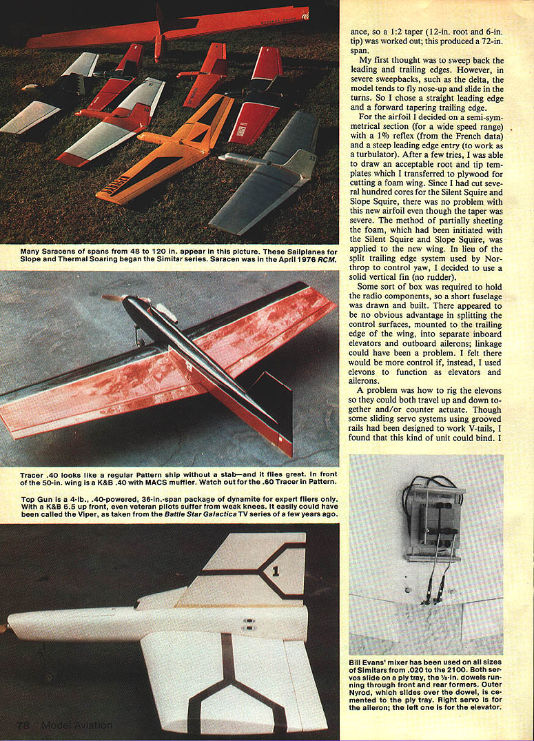
- I designed a sliding tray system using Nyrod tubing; 1/8-in dowels run through front and rear formers and outer Nyrod slides over the dowel cemented to the ply tray. The 1/8-in dowel eliminates binding.
First flights and CG lesson
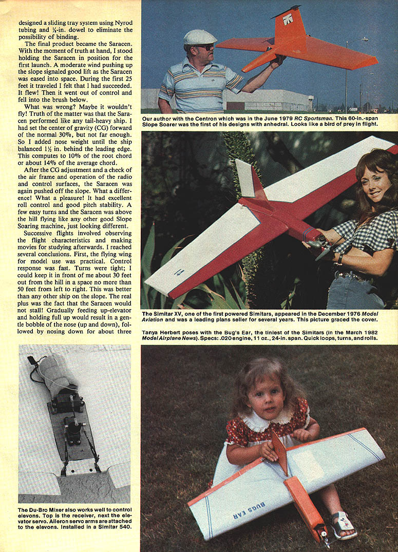
The first prototype, named Saracen, was launched from a slope. It teed off fine and then became uncontrollable and crashed. The cause: tail-heavy behavior — my initial CG location (near 30% chord) was not forward enough. I added nose weight until the ship balanced roughly 1 to 1.5 inches behind the leading edge (approximately 10% of the root chord and about 14% of the average chord). After that adjustment, Saracen flew very well: excellent roll control, solid pitch stability, and responsive turning.
Flight behavior and stall characteristics
Observations over successive flights and film study led to several conclusions:
- A flying wing model is practical and has fast control response.
- Turns are tight — I could keep the model about 30 ft out from the hill and within a 50-ft lateral corridor, better than other slope ships.
- Saracen exhibited benign stall behavior: gradually holding up-elevator produced a gentle bobble (nose up, then down) followed by a recovery rather than a sudden wing-drop. Explanation: the leading edge stalls first, locally reducing lift and automatically reducing the wing's angle of attack before the entire wing stalls.
Evolution of the Saracen Family
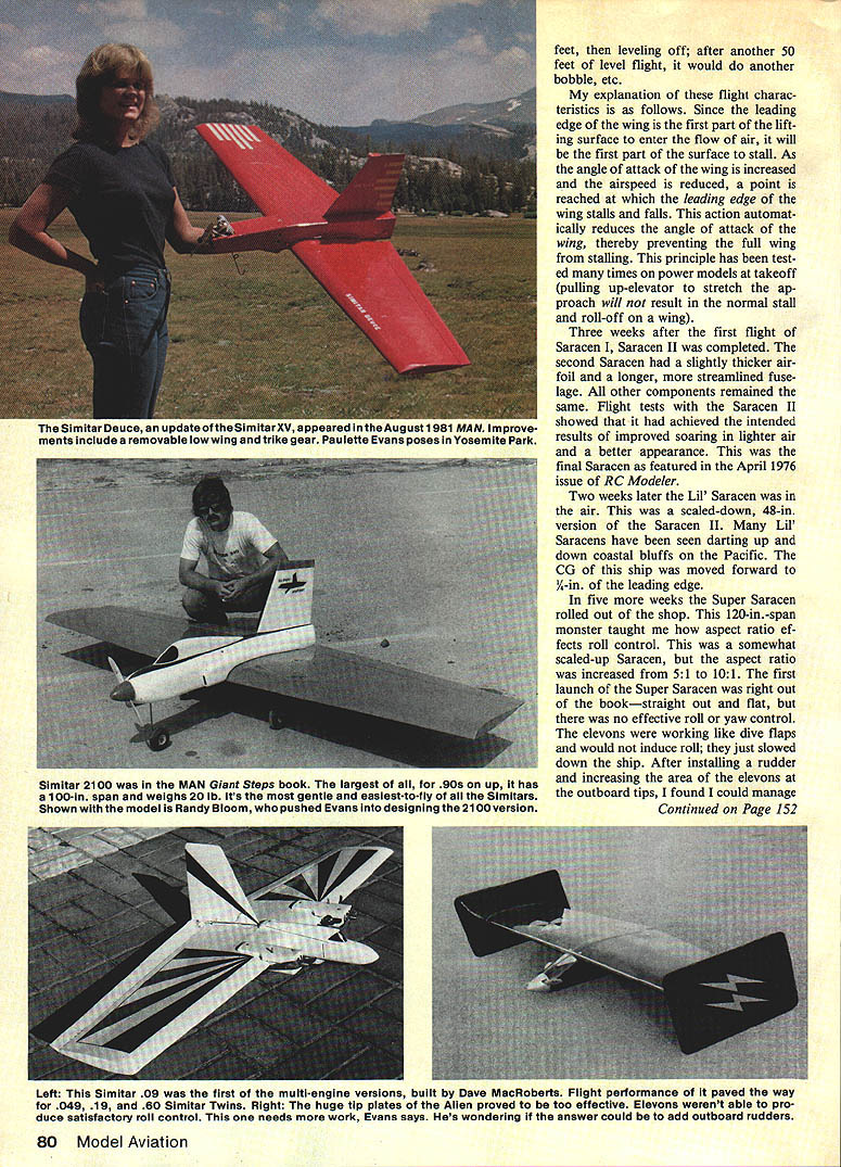
- Saracen II: Slightly thicker airfoil and a longer, more streamlined fuselage. Better soaring in lighter lift and improved appearance. (Featured in RCM, April 1976.)
- Lil' Saracen: A 48-in scaled-down version. Many have been flown along coastal bluffs. CG was moved forward to about 1/4 in from the leading edge on that design.
- Super Saracen: A 120-in span, higher aspect ratio (increased from 5:1 to 10:1). The first launches were straight and flat but showed little effective roll or yaw control — elevons acted more like dive flaps. Adding a rudder and increasing outboard elevon area helped, but these flights taught that roll sluggishness increases as aspect ratio increases.
Conclusion on aspect ratio: Aspect ratios below about 7:1 give satisfactory roll control; I recommend between 5:1 and 6:1 for balanced roll responsiveness.
Powered Flying Wings — The Simitar Line and Beyond
Early powered designs
- Simitar: a 1/2A version based on Lil' Saracen.
- Simitar XV: based on Saracen; both had terrific performance and lots of speed. Test flights could be unnerving on power but were rewarding once mastered. Construction articles were published (RCM and Model Aviation, Dec 1976).
Small and larger powered variants
- Bugs Ear: a 24-in span, TD .020-powered model at 10.5 oz (with Cannon Mini system). It rolled very quickly and even could be launched from a car dashboard.
- Simitar 540: used the Saracen wing cut to 50 in. Initially powered by a K&B .40, later K&B 6.5 and 7.5. Four channels: two for the sliding-tray control surfaces, one for throttle, one for steerable nose wheel. Performance: outrageous vertical climbs, smooth and quick control response, capable of loops, rolls, and excellent inverted flight. The 540 requires active flying — it rewards pilot attention.
Gear placement tips (Simitar 540 experience)
- Place main gear 1 in behind the CG.
- Set nose wheel height so the wing leading edge is about 5/16 in higher than the trailing edge when resting on a flat surface.
- Bend main gear wheels forward or rearward so that about 3–4 oz of finger pressure on the aft tip of the fin will lift the nose wheel. This helps rotation on takeoff and makes the ship settle properly at touchdown.
Twins and X-wings
- I experimented with twin engines (.09 twin, .19 twin, .049 twin, .60 twin). Contrary to fears of uncontrolled one-engine-out spins, the first .09 twin flew well on one engine (loops, rolls, etc.).
- Astron (X-wing): The first Astron (.15) proved practical and showed strong visual and performance appeal (Model Aviation, Apr 1979). A .40 Astron based on the Simitar 540 wing was very easy to handle; a notable trait was the ability to fly low-speed fly-bys at a high nose angle and then jam throttle for a straight-up climb — it would not stall.
- Double X-wing (two Astron .40s joined at the tips): great performance with both engines, but when one engine failed the large engine spacing caused a spin toward the dead engine.
Alternative control arrangements
I experimented with rigging the lower wing for ailerons and the top wing for elevators on a biplane-like X-wing. It worked, though control response was somewhat slower than with elevons, and more down-stick was needed for inverted flight.
Inverted flight note
Flying wings typically require more down-elevator to remain inverted because of the reflexed airfoil. Set the elevons at a small amount of up at neutral (about 1/2 in up at neutral is a useful starting point with transmitter trim centered); when inverted, more down-stick is needed to achieve the equivalent reflex for inverted flight.
Large Ships, Skywalker, and Structural Lessons
- Simitar 2100: Largest Simitar with a 100-in span, ~22 lb, powered by a .90 glow or a Quadra. With 14 sq ft of wing it almost floats and is the easiest-to-fly of the Simitars. (Featured in Giant Steps, Model Airplane News.)
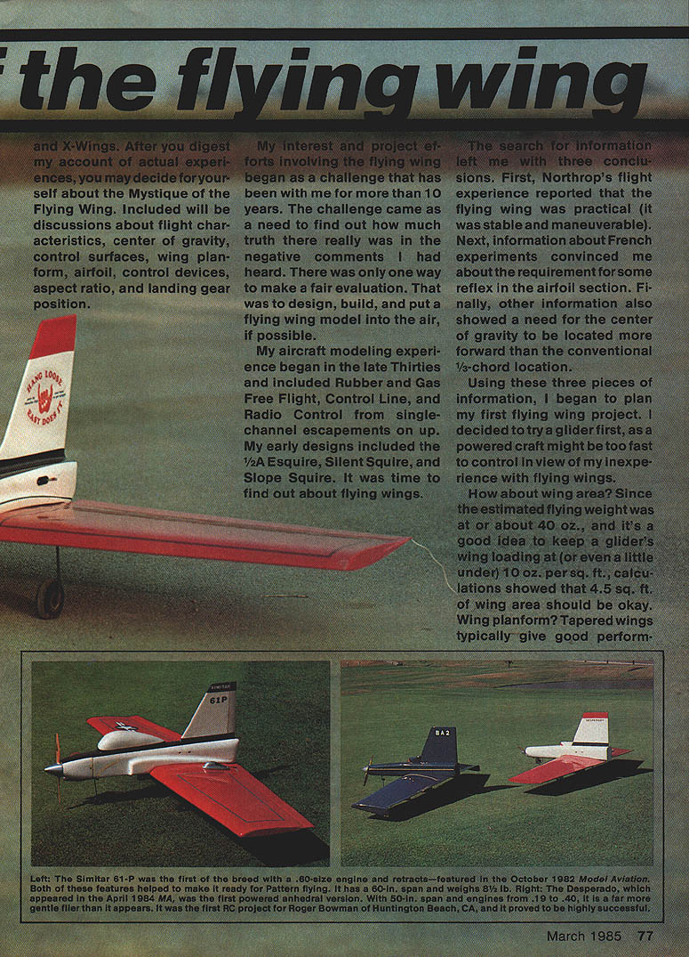
- Skywalker: a stretched-fuselage version of the 540, built in 1/2A, .40, and .60 sizes. An initial rear-swept-wing Skywalker was discarded because it flew a bit nose-up and tended to slide in turns. Returned to the original Simitar wing planform.
Flutter and control-surface strength
Severe flutter problems were encountered when a Webra .60 with tuned pipe was installed on some Skywalker/Simitar .60-size ships. The additional power increased dynamic pressures beyond the limits of pushrods and servo torque, destroying several models. Remedies that worked included:
- Using 1/8-in piano wire pushrods and high-torque (35+ in-oz) servos to overpower control surfaces and eliminate flutter.
- The better long-term answer is to statically and dynamically balance control surfaces on the .60-size ships.
High-performance Designs: Desperado, Top Gun, Alien
- Desperado and Top Gun: designs with anhedral and high-performance setups. Powered by a K&B 6.5 with MAC muffler, these designs deliver outrageous performance and very high roll rates (Top Gun in particular).
- Alien: intended as a counterpart to the Top Gun with huge tip verticals. In practice, the huge tip verticals provided excessive stability that overwhelmed elevon roll authority — two test hops resulted in straight flights with no roll response; the model would not turn under power and required cutting power to land. This over-stability needs resolution.
Current and future work (as of the article):
- A twin K&B 8.3s ducted-fan Top Gun and trials with multiple K&B 7.5s in a giant Top Gun were in progress.
- Bill Winter encouraged a lightweight Simitar with a .15 engine for slow, easy flying (Simitar Slow Motion), possibly with a built-up wing.
If there is a limit to this saga, it has not yet been reached.
Acknowledgements
First, my thanks to the many readers who wrote and phoned to tell me about their experiences, especially with the Simitar. Your interest and participation make the effort worthwhile.
By name (and brief note of contribution):
- Bill Braatz (Indiana): taught me to fly control line and encouraged me to build flying wings.
- Wayne Sakamoto: Master-class pattern flier who learned on the Saracen and still competes with a 540.
- Randy Bloom (San Clemente, CA): began with the Simitar and pushed me to design the 2100; he built the first one.
- Dave Herbert (Capistrano, CA): outstanding X-wing pilot; won with the Astron .40 at the Multi-Wing Nationals in 1979.
- Frank Johnson: built and flew many unconventional designs, including the Double X-Wing.
- John Ludwig: principal Skywalker pilot in Bishop, CA.
- Gus Morris: turned sketches and ships into superb drawings for construction articles.
- Skynauts of Saddleback Valley (President Andy Soptick): strong support and infectious enthusiasm for the Simitar.
- Bill Winter, Don Dewey, Carl Wheeler, Art Schroeder, and Dick Kidd: instrumental in organizing the Northrop contest and supporting flying wing activities.
Finally, special thanks to my wife Joan and our children, who lived through each new project without complaint. I owe them much.
To all above and many others too numerous to mention: thank you for your friendship, support, help, and encouragement in my encounter with the Mystique of the Flying Wing.
Bibliography
- Saracen — RCM, April 1976 (72-in. glider)
- Simitar — RCM, December 1976 (48-in., 1/2 A)
- Simitar XV — Model Aviation, December 1976 (54-in., 1/5)
- Simitar 540 — RCM, October 1978 (50-in., .40)
- Simitar Twin XIV — Model Aviation, April 1980 (60-in., Twin, .19)
- Astron — Model Aviation, April 1979 (32-in., X-Wing, .15-.19)
- Centron — RCS, June 1979 (60-in., Glider)
- Astron .40 — RCM, November 1979 (40-in., X-Wing, .40)
- Simitar 61-P — Model Aviation, October 1982 (60-in., Pattern, .60)
- Simitar Deuce — Model Airplane News, August 1981 (54-in., .21)
- Bugs Ear — Model Airplane News, March 1982 (24-in., .020)
- Simitar 2100 — Model Airplane News — Giant Steps, 1982 (100-in., 22 lb., .90/Quadra)
- Silent Squire — RCM, February 1975 (60-in., Slope and Thermal)
- Slope Squire — RCS, January 1977 (60-in., Slope, Low Wing)
- Hot Rock — Model Aviation, November 1977 (50-in., .40 Sport, Low Wing)
- Hole Card — RCS, September 1976 (48-in., .09 Sport, High Wing)
- Winterhawk — Model Aviation, May 1978 (100-in., Thermal Glider)
- Dasher — Model Aviation, October 1978 (40-in., .25-.35 Sport, Low Wing)
- Seville — Model Aviation, May 1977 (80-in., Thermal, Low Wing)
Transcribed from original scans by AI. Minor OCR errors may remain.

