
For Navy Carrier — The MARTIN MO-1
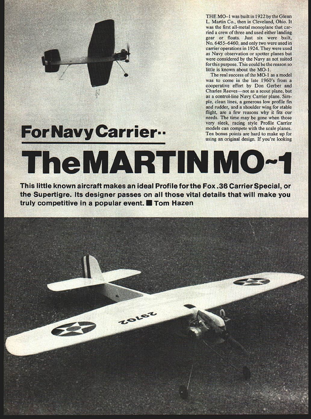
THE MO-1 was built in 1922 by the Glenn L. Martin Co., then in Cleveland, Ohio. It was the first all-metal monoplane that carried a crew of three and could be equipped with either landing gear or floats. Just six were built (No. 6455–6460), and only two were used in carrier operations in 1924. They were used as Navy observation or spotter planes but were considered by the Navy as not ideally suited for this purpose. This may be the reason so little is known about the MO-1.
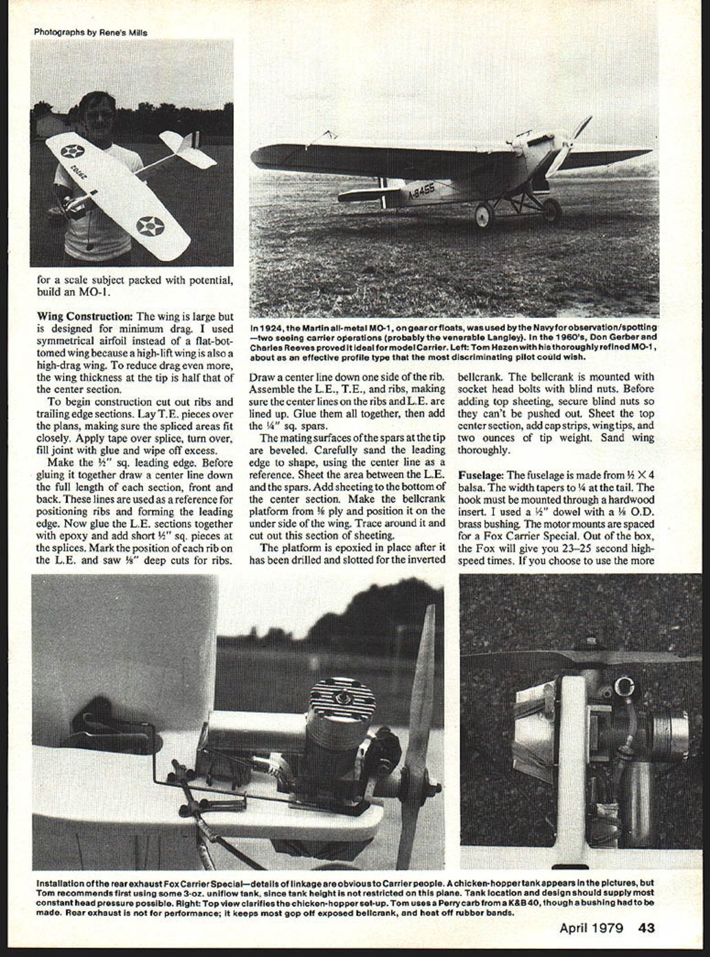
The real success of the MO-1 as a model came in the late 1960s from a cooperative effort by Don Gerber and Charles Reeves — not as a scout plane, but as a control-line Navy Carrier model. Simple, clean lines, a generous low-profile fin and rudder, and a shoulder wing for stable flight are a few reasons why it fits our needs. Ten bonus points are hard to make up for using an original design. If you're looking for a competitive Profile Carrier design, this little-known aircraft makes an ideal profile for the Fox .36 Carrier Special or the Supertigre. Its designer passes on the vital details that will make you truly competitive in a popular event. — Tom Hazen
Wing Construction
The wing is large but is designed for minimum drag. I used a symmetrical airfoil instead of a flat-bottomed wing because a high-lift wing is also a high-drag wing. To reduce drag even more, the wing thickness at the tip is half that of the center section.
Construction steps:
- Cut out ribs and trailing edge (T.E.) sections.
- Lay T.E. pieces over the plans, making sure the spliced areas fit closely. Apply tape over the splice, turn over, fill the joint with glue and wipe off excess.
- Make the 1/2" square leading edge (L.E.). Before gluing it together draw a center line down the full length of each section, front and back. These lines are used as a reference for positioning ribs and forming the leading edge.
- Glue the L.E. sections together with epoxy and add short 1/4" square pieces at the splices. Mark the position of each rib on the L.E. and saw 3/16" deep cuts for the ribs.
- Draw a center line down one side of each rib. Assemble the L.E., T.E., and ribs, making sure the center lines on the ribs and L.E. are aligned. Glue them together, then add the 1/4" square spars.
- Bevel the mating surfaces of the spars at the tip. Carefully sand the leading edge to shape, using the center line as a reference. Sheet the area between the L.E. and the spars. Add sheeting to the bottom of the center section.
- Make the bellcrank platform from 1/8" plywood and position it on the underside of the wing. Trace around it and cut out this section of sheeting. The platform is epoxied in place after it has been drilled and slotted for the inverted bellcrank.
- Mount the bellcrank with socket-head bolts and blind nuts. Before adding top sheeting, secure blind nuts so they can't be pushed out. Sheet the top center section, add cap strips, wing tips, and two ounces of tip weight. Sand the wing thoroughly.
Fuselage
The fuselage is made from 1/2" x 4" balsa. The width tapers to 1/4" at the tail. The hook must be mounted through a hardwood insert. I used a 1/4" dowel with a 3/8" O.D. brass bushing. The motor mounts are spaced for a Fox Carrier Special. Out of the box, the Fox will give you 23–25 second high-speed times. If you choose to use the more popular Supertigre, the mounts will have to be spaced at 1-1/4".
Landing gear details:
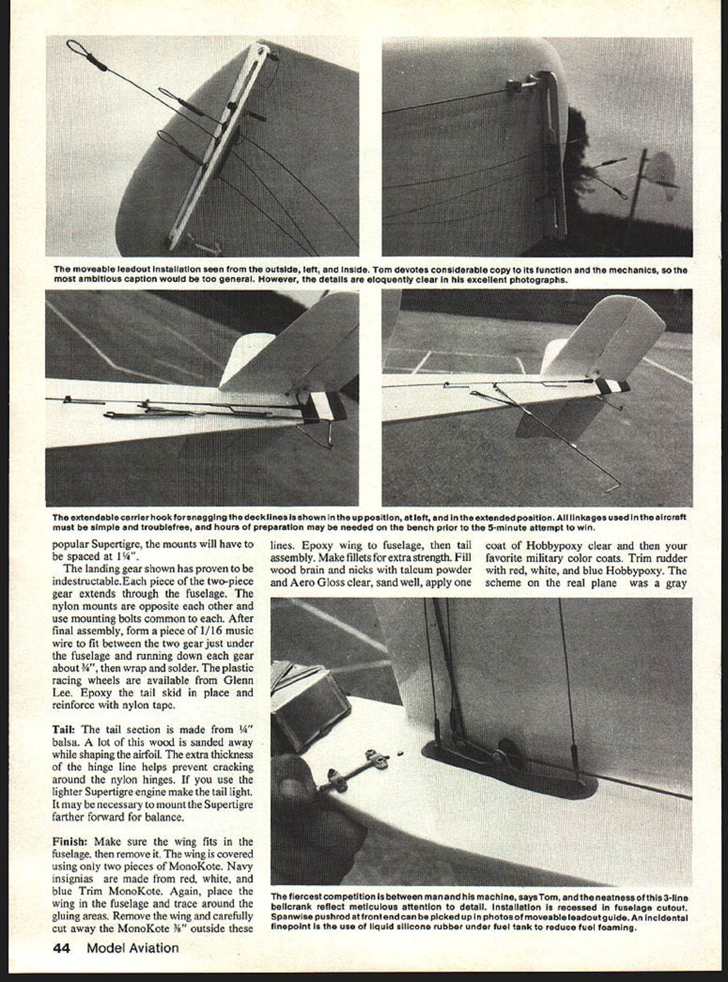
- The landing gear shown has proven to be indestructible. Each piece of the two-piece gear extends through the fuselage. The nylon mounts are opposite each other and use mounting bolts common to both.
- After final assembly, form a piece of 1/16" music wire to fit between the two gear just under the fuselage and running down each gear about 3/4", then wrap and solder.
- The plastic racing wheels are available from Glenn Lee.
- Epoxy the tail skid in place and reinforce with nylon tape.
Tail
The tail section is made from 1/4" balsa. A lot of this wood is sanded away while shaping the airfoil. The extra thickness at the hinge line helps prevent cracking around the nylon hinges. If you use the lighter Supertigre engine make the tail light; it may be necessary to mount the Supertigre farther forward for balance.
Finish
- Make sure the wing fits in the fuselage, then remove it.
- Cover the wing using only two pieces of MonoKote. Navy insignias are made from red, white, and blue Trim MonoKote.
- Place the wing in the fuselage and trace around the gluing areas. Remove the wing and carefully cut away the MonoKote 3/8" outside these lines.
- Epoxy wing to fuselage, then tail assembly. Make fillets for extra strength.
- Fill wood grain and nicks with talcum powder and Aero Gloss clear, sand well, apply one coat of HobbyPoxy clear and then your favorite military color coats.
- Trim rudder with red, white, and blue HobbyPoxy.
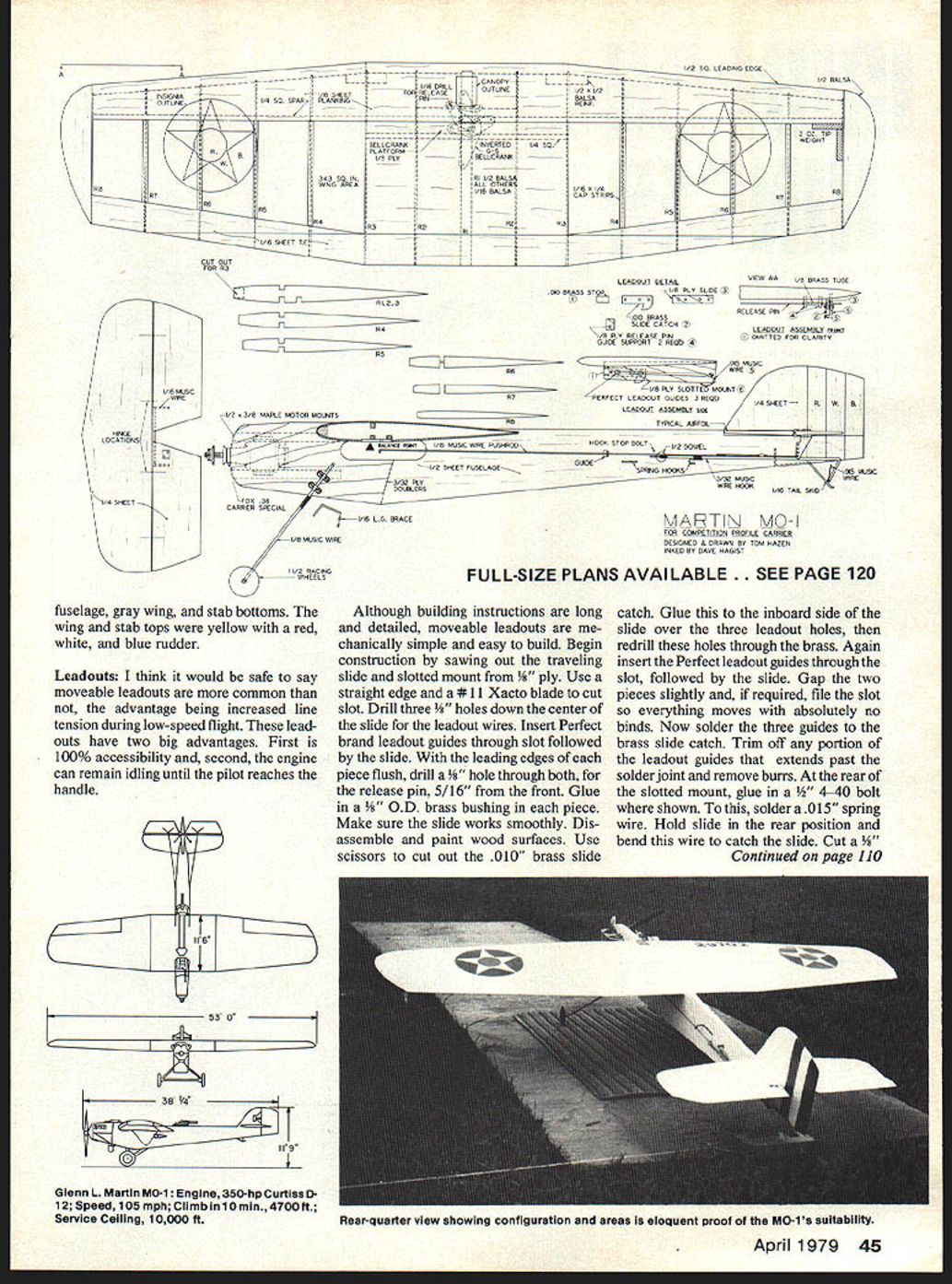
The scheme on the real plane was a gray fuselage, gray wing, and stab bottoms. The wing and stab tops were yellow with a red, white, and blue rudder.
Leadouts
I think it would be safe to say moveable leadouts are more common than not, the advantage being increased line tension during low-speed flight. These leadouts have two big advantages:
- 100% accessibility.
- The engine can remain idling until the pilot reaches the handle.
Although building instructions are long and detailed, moveable leadouts are mechanically simple and easy to build.
Construction summary:
- Saw out the traveling slide and slotted mount from 1/8" plywood. Use a straight edge and a #11 X-Acto blade to cut the slot.
- Drill three 1/8" holes down the center of the slide for the leadout wires.
- Insert Perfect-brand leadout guides through the slot followed by the slide. With the leading edges of each piece flush, drill a 1/8" hole through both for the release pin, 5/16" from the front. Glue in a 5/16" O.D. brass bushing in each piece. Make sure the slide works smoothly.
- Disassemble and paint wood surfaces. Cut out the .010" brass slide catch and glue it to the inboard side of the slide over the three leadout holes, then redrill these holes through the brass. Reinsert the leadout guides through the slot followed by the slide. Gap the two pieces slightly and, if required, file the slot so everything moves with absolutely no binds.
- Solder the three guides to the brass slide catch. Trim any portion of the leadout guides that extends past the solder joint and remove burrs.
- At the rear of the slotted mount, glue in a 1/8" 4-40 bolt where shown. To this, solder a .015" spring wire. Hold the slide in the rear position and bend this wire to catch the slide.
- Cut a 1/8" wide groove on the underside of the inboard wing tip to accept the slotted mount and epoxy it in place.
- Attach leadout cables, elevator pushrod, throttle linkage, and release pin to the bellcrank. The 1/16" music wire release pin is attached to the bellcrank through a 1/16" hole and extends through a 5/8" brass tube guide, slide, and slotted mount. Trim the release pin so that at approximately 10% throttle the pin releases the slide.
- File the tip of the release pin to a point to guarantee smooth action. The release pin must extend at least 3/8" to 1/2" past the slotted mount so the leadouts aren't accidentally tripped on takeoff.
- Support the 5/8" brass guide tube with two small pieces of 1/8" plywood glued to the wing through the sheeting. Ensure the release pin does not bind in the tube.
- With the throttle in full position and the leadouts locked forward, epoxy the .010" brass tab to the slotted mount and bend it 90 degrees to touch the slide. This tab enables you to line up and lock the slide in place while you're at the handle.
The moveable leadouts described and shown on the plans vary slightly from the photos; the photos show an extra lock at the rear and a slightly different slide catch. That extra lock was for experimenting with different line sweeps. The results were that the more sweep, the better the handling characteristics.
Hardware, Fuel Tanks and Engine
Now it's time to add other small hardware items: pushrod guide, throttle guide, removable hook, hook release and stop, and gas tank. Most of these items are self-explanatory, but the real secret is to make them simple and trouble-free. Almost all linkage problems can and should be solved on the bench. Hours and hours of preparation go into that five-minute attempt for the winning score; if something can go wrong, it happens then. The fiercest conflict in competition Carrier is man against machine.
Fuel tank notes:
- Some items seen in the photos may not be recommended in all cases. The chicken-hopper gas tank is one such item. The Fox Carrier Special seems to be particular about the fuel system. Tank location and design should supply the most constant head pressure possible.
- I recommend using a simple 3-oz. uniflow tank first before using the more complicated chicken hopper, because the MO-1 design doesn't restrict tank elevation. In my opinion you can't buy a tank better than one you can make yourself.
- If you need a custom-fit tank, make it from .008" or .010" brass (.010" is more difficult to bend). If you're satisfied with a commercial tank, resolder all joints and tubes with Sta-Brite solder.
- Tanks mounted with bolts have a tendency to crack from vibration. The tank should be mounted with rubber bands and the back side cushioned with dots of silicone sealer to protect the finish.
Carburetor and exhaust:
- Chances are your greatest fuel problem will not be the tank, but the stock carb. Idle is generally poor and usually you end up in trouble during low-speed flight.
- Replace the stock carb if necessary. Replace it with an H.P. .40 or, better yet, a Perry carb. I use a Perry that was made for a K&B .40 with an aluminum bushing necessary for it to fit the engine. The bushing is not available off the shelf and has to be made. Another modification to the Perry carb is a longer throttle arm to increase throttle movement at the handle.
- The exhaust extension is not for increased performance. Performance is not increased or decreased, but the extension does keep a lot of oil off the exposed bellcrank and keeps exhaust heat off the rubber bands that hold the tank. Use a rear-exhaust installation when possible.
Recommended engines and mounts:
- Use a Fox Carrier Special out of the box; Fox will give details on linkage and installation obvious to Carrier people. The Fox will give 23–25 second high-speed times. Choose the rear-exhaust installation.
- If you use the Supertigre, the mounts should be spaced at 1-1/4".
Landing gear (summary):
- The landing gear on the full-size Martin MO-1 was all-metal; floats were used by the Navy for observation/spotting. Two-seaters likely saw carrier operations aboard the Langley in the 1920s.
- On the model, the two-piece gear as shown has proven indestructible: each piece extends through the fuselage with nylon mounts opposite each other and common mounting bolts. After final assembly, form a piece of 1/16" music wire to fit between the two gear just under the fuselage, running down each gear about 3/4", then wrap and solder. Epoxy the tail skid and reinforce with nylon tape.
Flying
After an engine break-in period and pre-flight check, with the handle in your hand:
- Swing the handle to the left bringing the leadouts fully forward.
- Increase throttle to full, locking the leadouts in place, and signal for release.
- Climb should be gradual without engine hesitation. The MO-1 grooves as well as my Magician through the fast laps.
- After the seventh lap, decrease throttle slowly. When the leadouts trip, the plane will climb 3' to 5' due to the angle changes of the lines if you use the type of bellcrank shown. If you use the J. Roberts bellcrank the plane will lose altitude.
- Low-speed flight is smooth and predictable. It's very easy to handle. Even with a large wing, a nose-high attitude can be achieved.
- The landing approach should be gradual, using the throttle to control altitude. When the mousetrap hook snags a line it stays snagged.
I don't claim this design of the MO-1 is the ultimate Profile Carrier plane that must be built exactly this way. Try it and possibly use your own ideas to improve it. I would be glad to hear of improvements or answer questions. The MO-1 is truly a natural.
Observations on Profile Carrier
Although I'm a relatively new carrier flier, and geographically isolated from intense carrier activity, I've been able to form some valid opinions. A few brief, random thoughts:
- An effort has been made to make Profile Carrier a beginner's event. A beginner's skill and ability are often underestimated. Profile Carrier is not a beginner's event, but it is a good place to begin.
- Beginners look up to experienced fliers. A few words of praise or sincere interest in a beginner's equipment will do more to encourage him than any other single factor.
- Finally, the people that fly carrier are the greatest. Get to know them.
Transcribed from original scans by AI. Minor OCR errors may remain.

