
NAVY FLIER
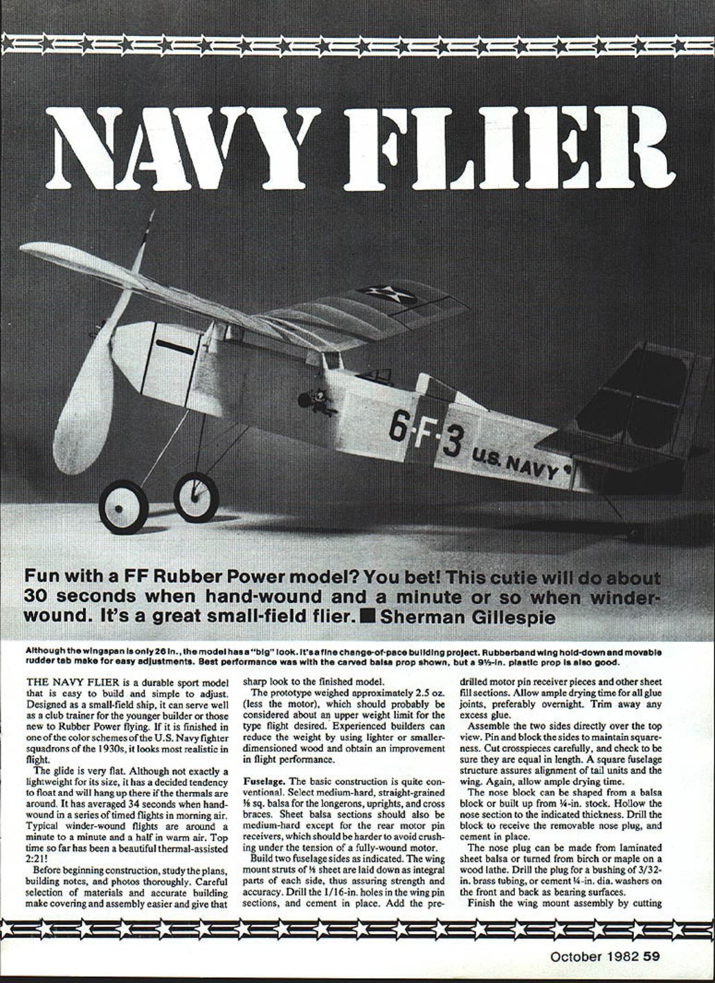
Although the wingspan is only 26 in., the model has a "big" look. It's a fine change-of-pace building project. A rubber-band wing hold-down and a movable rudder tab make for easy adjustments. Best performance was with the carved balsa prop shown, but a 9-1/2-in. plastic prop is also good.
The Navy Flier is a durable sport model that is easy to build and simple to adjust. Designed as a small-field ship, it can serve well as a club trainer for the younger builder or those new to rubber-power flying. Finished in one of the U.S. Navy fighter squadron color schemes of the 1930s, it looks especially realistic in flight.
Flight characteristics:
- Glide is very flat and the model tends to float; it will hang up well in thermals.
- Hand-wound timed flights have averaged about 34 seconds in morning air.
- Typical winder-wound flights are around 1:00 to 1:30 in warm air.
- Top time recorded: a thermal-assisted 2:21.
Before beginning construction, study the plans, building notes, and photos thoroughly. Careful selection of materials and accurate building make covering and assembly easier and give a sharp, finished appearance.
Prototype weight: approximately 2.5 oz (less the motor). This should be considered about the upper weight limit for the intended flying characteristics. Experienced builders can improve performance by using lighter or smaller-dimensioned wood.
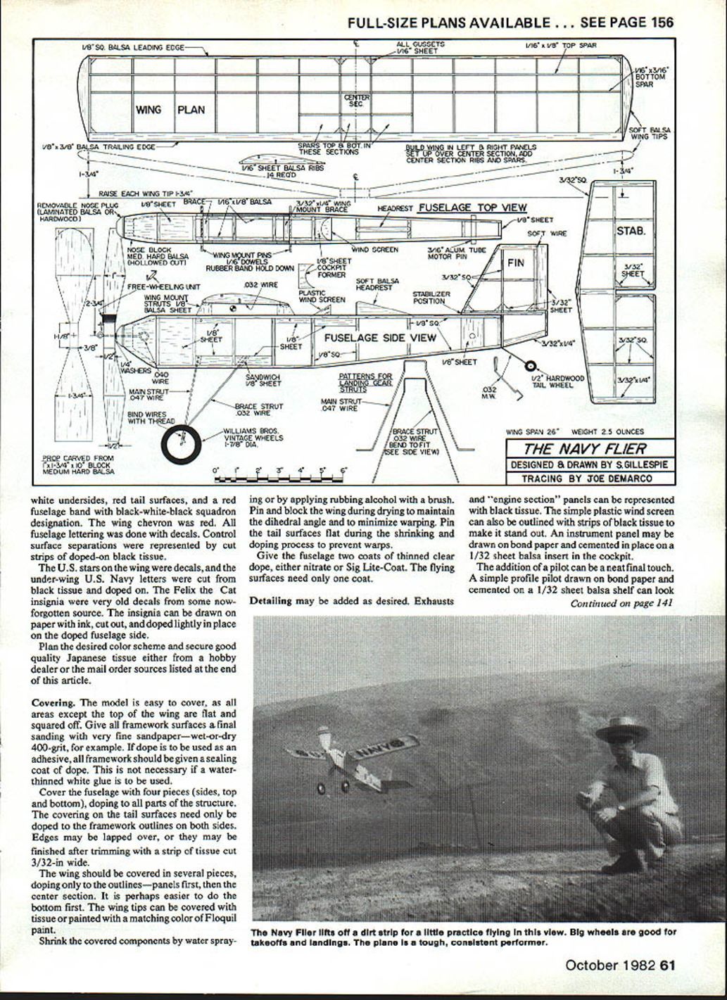
Fuselage
The basic construction is conventional.
- Use medium-hard, straight-grained 1/8-in. square balsa for the longerons, uprights, and cross braces. Sheet balsa should be medium-hard except for the rear motor-pin receivers, which should be harder to resist crushing under motor tension.
- Build two fuselage sides as shown on the plans. The wing-mount struts (1/16-in. sheet) are laid down as integral parts of each side for strength and accuracy.
- Drill the 1/16-in. holes in the wing-pin sections and cement them in place. Add the pre-drilled motor-pin receiver pieces and other sheet fill sections. Allow ample drying time for all glue joints, preferably overnight. Trim away any excess glue.
- Assemble the two sides over the top view. Pin and block the sides to maintain squareness. Cut crosspieces carefully and ensure they are equal in length. A square fuselage assures alignment of the tail units and wing. Allow ample drying time.
- The nose block may be shaped from a balsa block or built up from 1/4-in. stock. Hollow the nose section to the indicated thickness. Drill the block to receive the removable nose plug and cement it in place.
- The nose plug can be laminated from sheet balsa or turned from birch or maple. Drill the plug for a 3/32-in. brass-tubing bushing, or cement 1/4-in. diameter washers on the front and back as bearing surfaces.
- Finish the wing-mount assembly by cutting small grooves in the wing struts. Cut pieces of 1/32-in. wire to size and cement in place. Cement balsa cross braces to serve as rests for the leading and trailing edges of the center section and to tie the wing mount rigidly together.
Landing gear
- Bend the gear legs to the shapes shown on the patterns.
- Cement a side-sheet balsa sandwich in place on the fuselage; let dry. Insert the wire gear legs to allow adjustment for squareness, then cement thoroughly and add the other half of the balsa sandwich so it fits snugly. Check trueness before the glue sets.
- If fuselage and gear are properly aligned, the finished model will sit squarely — it is frustrating to find the wing lower on one side because the landing gear is crooked.
- Bind the legs together with thread and cement.
- Williams Brothers 1-1/4-in. Vintage Golden Era wheels look sharp, but wooden or plastic wheels will also work. About 2-in. diameter wheels give a good scale appearance; many old fighters had prominent wheels.
- Hold wheels on with short pieces of tight-fitting plastic tubing; a drop of glue will secure them.
- The tail wheel can be hardwood or laminated balsa. Fit a 1/16-in. brass-tubing bushing, bend the tail-wheel wire to shape, and cement in place; hold the wheel on with a drop of glue on the axle end.
Tail surfaces
- Stabilizer and rudder are made from medium-sized 3/32-in. square strips. Tips, gussets, and the rudder tab are cut from medium 3/32-in. sheet. The rudder tab is fixed.
- Use three soft-wire hinges inserted in holes made by carefully piercing the balsa. Paper ties (from plastic garbage bags) are a good source of soft wire.
Wing structure
- Wing structure is standard; use medium-hard wood.
- Cut 14 ribs from 1/16-in. sheet using a template made from hard balsa, aluminum, or 1/32-in. model plywood. Stack, pin, and sand the ribs for uniformity. Cut spar notches as indicated.
- Lay out the leading and trailing edges for left and right panels and cement the ribs in place, except for the wing-root ribs.
- Wing tips are carved from soft balsa. Finish-sand the tips to final contour when panels are dry. Trim and sand the leading and trailing edges to complete the airfoil shape.
- Set up the panels over the plan and block up the tips to the correct dihedral. Add the wing-root ribs, leading and trailing edge pieces, and gussets. Additional spars across the center and wing-root sections improve strength and covering support.
Propeller
- Various props of 9 to 10 in. diameter may be fitted. A 9-1/2-in. plastic prop will work well; the best performance in tests was with a wide-bladed 10-in. balsa carved prop.
- Key points for a carved prop:
- Prepare a proper blank and drill for the shaft bushing before carving.
- Carve the backs of the blades first, from flat to concave.
- Carve the faces (flat then curved), sand, and shape one blade to the desired outline. Trace it onto paper to use as a pattern for the other blade.
- Balance carefully and give several coats of thinned dope, sanding lightly between coats.
- For extra strength, cover the prop with Japanese tissue or lightweight silk.
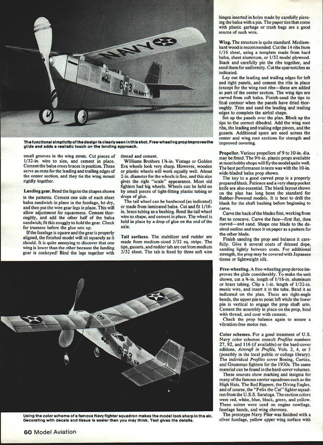
Free-wheeling
A free-wheeling prop device improves the glide considerably.
- To make the unit shown on the plan: cut a 3/8-in. length of 1/16-in. aluminum or brass tubing. Clip a 1-in. length of 1/32-in. music wire and insert it in the tube. Bend as indicated on the plan so the upper pin points left and the lower pin is vertical to engage the prop-shaft arm.
- Cement the assembly in place on the prop, bind with thread, and coat with cement.
- Check prop balance again to assure a vibration-free motor run.
Color schemes
For a good treatment of U.S. Navy color schemes consult Profiles numbers 27, 92, and 116 or the hard-cover editions Aircraft in Profile, Vols. 2, 4, or 5 (local public or college libraries may have them). These cover Boeing, Curtiss, and Grumman fighters of the 1930s and show markings and insignia for carrier squadrons such as the High Hats, The Red Rippers, the Diving Eagles, and "Felix the Cat" of the U.S.S. Saratoga. Section colors included red, white, blue, black, green, and yellow for cowlings, fuselage bands, and wing chevrons.
Prototype finish:
- Silver fuselage
- Yellow upper wing surface with white undersides
- Red tail surfaces
- Red fuselage band with black-white-black squadron designation
- Red wing chevron
- Fuselage lettering applied with decals; control-surface separations represented by doped-on black tissue
- U.S. stars on the wing applied with decals; under-wing U.S. Navy letters cut from black tissue and doped on
- Insignia (e.g., Felix the Cat) can be drawn on paper, cut out, and lightly doped in place
Plan your color scheme and secure good-quality Japanese tissue from a hobby dealer or mail-order sources.
Covering
- All framework should receive a final sanding with very fine sandpaper (e.g., 400-grit wet-or-dry).
- If dope is used as the adhesive, seal framework with a coat of dope first. This is not necessary if using a water-thinned white glue.
- Cover the fuselage with four pieces (sides, top, bottom), doping to all parts of the structure. Tail coverings need only be doped to the framework outlines on both sides; edges may be lapped or finished with a 3/32-in. wide strip of tissue.
- Cover the wing in several pieces, doping only to the outlines—panels first, then the center section. It may be easier to do the bottom first. Wing tips can be covered with tissue or painted with matching Floquil paint.
- Shrink covering by water spraying or applying rubbing alcohol with a brush. Pin and block the wing during drying to maintain dihedral and minimize warping. Pin tail surfaces flat during shrinking and doping to prevent warps.
- Give the fuselage two coats of thinned clear dope (nitrate or Sig Lite-Coat). Flying surfaces need only one coat.
- Add details as desired: exhausts and engine panels with black tissue, outline the windscreen with black tissue strips, and glue a printed instrument panel on a 1/32-in. balsa insert.
- A simple pilot profile drawn on bond paper and cemented to a 1/32-in. balsa shelf can be a neat final touch.
Flying
- Make an eight-strand, 15-in.-long motor from 3/16-in. Sig rubber. If using 3/16-in. FAI rubber (thicker), six strands may be sufficient. Lubricate the motor with rubber lube and wipe off excess.
- For testing with a free-wheeling prop, only slight motor slack is needed for positive disengagement. Use a #8 rubber band to hold the motor on the prop hook.
- Balance the model with the motor installed. The balance point should be close to the CG indicated on the plans.
- If the ship stalls in the glide, try slightly heavier wheels, move the wing back on the mounts, or decrease built-in incidence by shimming up the trailing edge slightly with a 1/32-in. sheet-balsa shim.
- Adjust for a long, flat glide, then add a very slight right rudder for a gentle right turn.
- For first power tests, try about 150 hand-wound turns. If a stall under power occurs, shim the nose plug for slight downthrust. Use side thrust only with great care; near-maximum turns can produce frightening ground strikes if the nose drops in a power spiral.
- Once smooth climb and consistent power-to-glide transition are attained, mark the nose-plug position so it can be reinserted the same way.
- As experience grows, work up to maximum safe winds with a winder. A well-lubed, 15-in., eight-strand motor of 3/16-in. Sig rubber (stretch-wound) should take about 300 turns easily. Experiment with longer motors for longer motor runs.
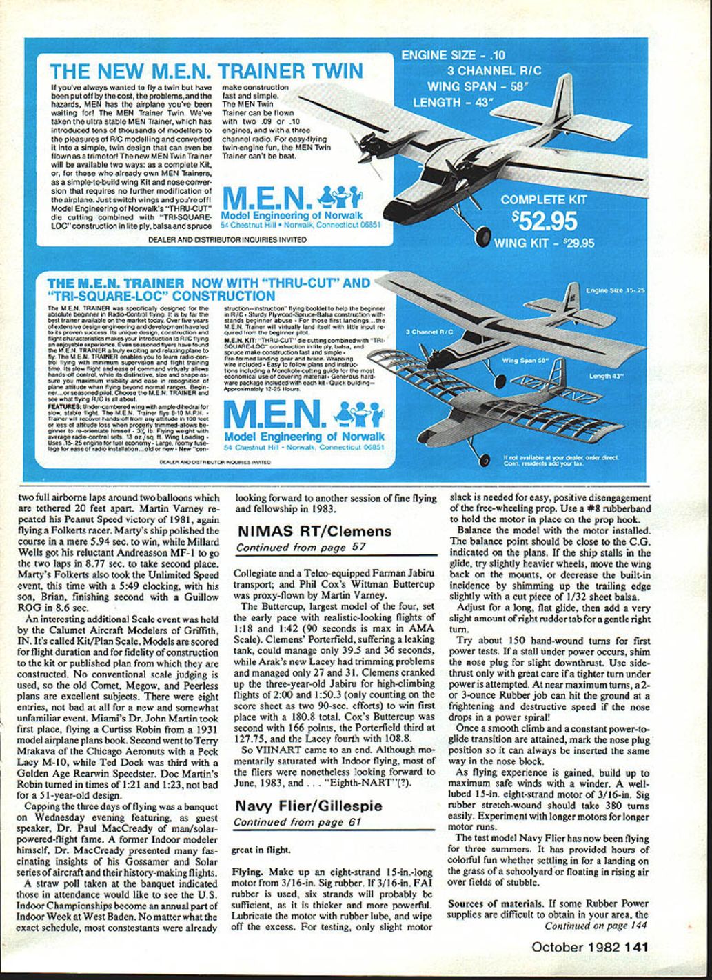
The test model has flown for several seasons, providing hours of enjoyable flying from schoolyard landings to floating in thermals over stubble fields.
Sources of materials
- Oldtimer Models, P.O. Box 913, Westminster, CA 92783. Japanese tissue, balsa prop blanks, tapered trailing-edge stock, hardwood and balsa wheels, brass washers, rubber motor, rubber lube, etc. Catalog $1.00.
- Peck-Polymers, P.O. Box 2498, La Mesa, CA 92401. Japanese tissue, plastic props, rubber lube, rubber motor, Williams Bros. wheels. Catalog $1.00.
- Sig Manufacturing Co., Inc., Route 1, Box 1, Montezuma, IA 50171. Sig rubber motor, rubber lube, balsa, tissue, plastic props and wheels. Catalog $2.00.
Transcribed from original scans by AI. Minor OCR errors may remain.

