
NBP-60
Al Masters
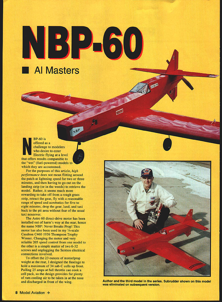
NBP-60 is offered as a challenge to modelers who desire to enter electric flying at a level that offers results comparable to the "wet" (fuel-powered) models to which they are accustomed.
For the purposes of this article, high performance does not mean flitting around the patch at lightning speed for two or three minutes, then having to go out on the landing strip (or in the weeds) to retrieve the model. Rather, it is more rewarding to take off from a rough grass strip, retract the gear, fly with a reasonable range of speed and acrobatics for five to eight minutes, drop the gear, land, and taxi back to the pit area without fear of the usual taxi noseover.
The Astro 60 direct-drive motor is installed out of harm's way at the rear; hence the name NBP: Never Breaks Prop! This motor has also been used in my 1/4-scale Caudron C460 (1936 Thompson Trophy winner). Changing the motor and the very reliable Astro 205 speed control from one model to the other is a simple matter of two 6-32 screws and unplugging the Sermos electrical connections involved.
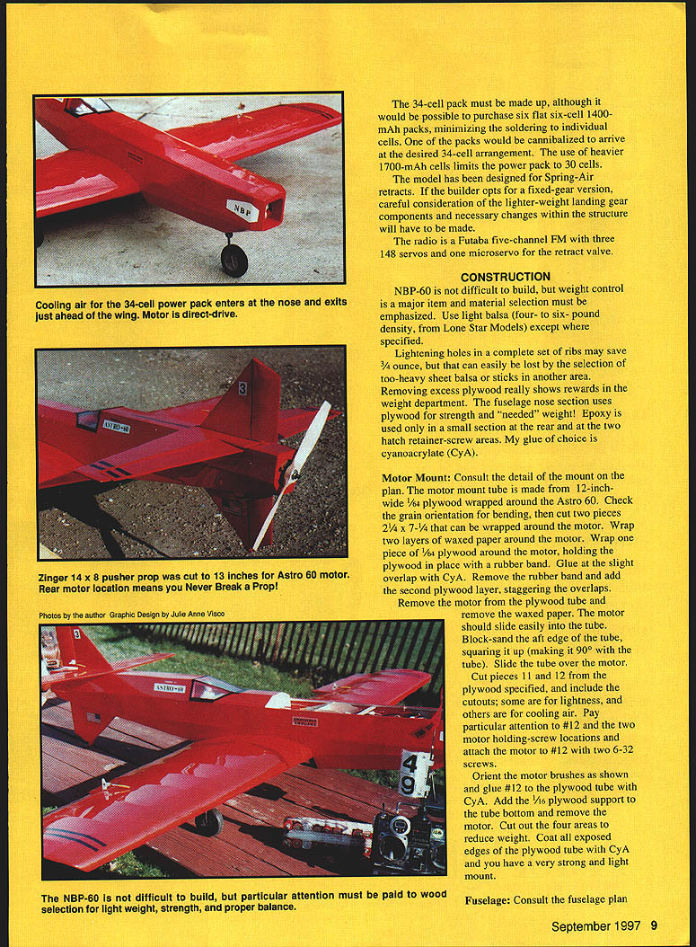
To offset the 23 ounces of motor/prop weight at the rear, the fuselage is designed to hold a maximum of 34 sub-C cells up front. Pulling 25 amps at full throttle can cook a cell pack, so the design provides plenty of ram cooling air to be taken in at the nose and discharged in front of the wing.
Construction
NBP-60 requires attention to detail and strict weight control. Material selection must be emphasized. Use light balsa (4–6 lb density, Lone Star Models) except where specified. Lightening holes in the complete set of ribs may save an ounce or two; conversely, selecting too-heavy sheet balsa or sticks can easily erase those savings. Removing excess plywood also yields clear rewards in the weight department.
The fuselage nose section uses plywood where strength is needed. Epoxy is used only in small areas at the rear and at the two hatch retainer-screw areas. Cyanoacrylate (CyA) is the preferred glue elsewhere.
Motor Mount
Consult the detail mount plan.
- The motor-mount tube is made from 1/4" plywood wrapped around the Astro 60. Check grain orientation for bending.
- Cut two pieces 2-1/4" x 7-1/4" that can be wrapped around the motor.
- Wrap two layers of waxed paper around the motor. Wrap one plywood piece around the motor, hold with a rubber band, and glue the slight overlap with CyA. Remove the rubber band and add the second plywood layer, staggering the overlaps.
- Remove the waxed paper; the motor should slide easily into the tube.
- Block-sand the aft edge of the tube, squaring it up (90°), then slide the tube over the motor.
Cut the specified plywood pieces (including those with cutouts for lightness and cooling air). Pay particular attention to the plywood piece that provides the two motor holding-screw locations; attach the motor with two 6-32 screws and orient the motor brushes as shown on the plan. Glue that piece to the plywood tube with CyA. Add the 1/16" plywood support to the tube bottom, cut out the four weight-reduction areas, and coat all exposed plywood edges with CyA. The result is a very strong, light mount.
Fuselage
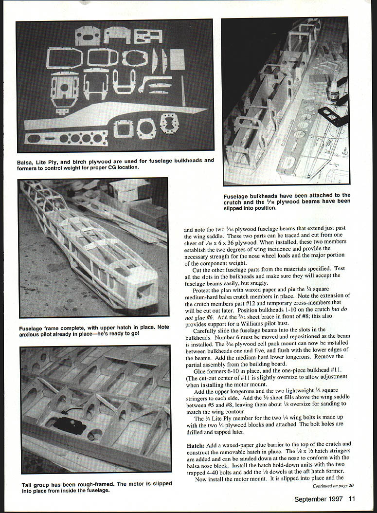
Consult the fuselage plan for stock selection to achieve light weight, required strength, and proper balance. Note the two 1/16" plywood fuselage beams that extend just past the wing saddle. These two parts can be traced and cut from one sheet of 1/16" x 6" x 36" plywood. When installed, they establish the two degrees of wing incidence and provide necessary strength for nose-wheel loads.
- Test all slots in the bulkheads to ensure they accept the fuselage beams easily but snugly.
- Protect the plan with waxed paper and pin the 1/4" square medium-hard balsa crutch members in place. Note the crutch extensions past temporary cross members that will be cut out later.
- Position bulkheads 1–10 on the crutch but do not glue #6 at this stage.
- Add the 3/32" sheet brace in front of #8; this also provides support for a Williams pilot bust.
- Carefully slide the fuselage beams into the bulkhead slots. #6 must be moved and repositioned as the beam is installed.
- Install the 3/16" plywood cell-pack mount between bulkheads 1 and 5, flush with the lower edges of the beams.
- Add the medium-hard lower longerons, then glue formers 6–10 in place and the one-piece bulkhead #11. (The center cutout of #11 is slightly oversize to allow adjustment when installing the motor mount.)
- Add the upper longerons and two lightweight 1/4" square stringers to each side.
- Add 1/8" sheet fillets above the wing saddle between #5 and #8, leaving about 1/8" oversize for sanding to match the wing contour.
- Make up the 1/8" Lite Ply member for the two 1/4" wing bolts with the two 1/4" plywood blocks; the bolt holes are drilled and tapped later.
The 34-cell pack must be made up. It is possible to purchase six flat six-cell 1400 mAh packs to minimize soldering. Individual cells can be cannibalized to arrive at the desired 34-cell arrangement; using heavier 1700 mAh cells limits the pack to 30 cells. The model was designed for Spring-Air retracts; if opting for a fixed-gear version, consider lighter-weight landing gear components and the necessary structural changes.
Hatch
- Add a waxed-paper glue barrier to the top of the crutch and construct the removable hatch in place.
- Add the 1/8" x 1/2" hatch stringers; they can be sanded down at the nose to conform with the balsa nose block.
- Install the hatch hold-down units with two trapped 4-40 bolts and add the 1/8" dowels at the aft hatch former.
Install the motor mount next. Slip the motor-mount plywood tube into place and pass it through bulkhead #11 so it extends about 1/8" past it. The opening in #11 allows the mount to be cocked for correct thrustline alignment. This is critical—after the mount is glued in place, no adjustments can be made. Epoxy at #11 is not fully applied until after the motor has been trial-fitted.
Install the motor by passing it through the bulkheads, starting at #8. Attach a 36" piece of 1/16" music wire to the motor shaft and, holding the fuselage vertical with the tail up, guide the motor to the plywood mount tube. The motor slips into place and is retained by the two 6-32 screws. Reverse the sequence to remove the motor.
Work with the nose-wheel unit and add the piece of 7/16" plywood sanded and placed to establish the correct angle to mount the retract unit. Four 4-40 screws and T-nuts hold the unit. Place a piece of 1/16" plywood over the T-nuts to guard against electrical contact with the Ni-Cd battery pack. Route the nose-wheel steering nyrod to the rudder-servo area.
Complete the rest of the fuselage by adding the servo mount, wing-hold blocks, etc. The 1/8" plywood part that holds the wing dowel to #5 is installed when the wing is fitted. Since the motor must be installed from inside the fuselage, run the elevator and rudder nyrods so a clear passage is maintained to the motor mount at the rear.
Tail Feathers
The tail group is very light, beefed up only in the skid and center sections. Build the upper fin and stabilizer together; add 1/16" plywood after removing the stabilizer from the building board. After hinges are installed, the tail group can be covered before attachment to the fuselage.
Wing
- Make a complete main lower spar by gluing 1/4" square hard balsa members to the 1/16" plywood dihedral brace. The two-piece spar build-up ends at rib #6.
- Make the 3/32" x 1/2" rear spar and shim it 3/32" off the building board.
- Make right and left rib sets with plywood doublers. Add ribs to the spar and the lower trailing-edge sheets.
- Attach the sub-leading edge and complete the wing framing with the ailerons.
- Cut the ailerons free and place the hinges. Install medium-hard diagonal shear braces before adding rib capstrips.
- After completing framing, position the servo mount and nylon aileron controls.
- Add two foam blocks (wing-bolt guides) and the 3/32" sheeting. Use a minimum of 3/32" wing sheeting around the wheel wells.
- When the 3/32" capstrips are installed, they may be omitted from aileron ribs 7–10.
Radio and Electronics
- Radio: Futaba five-channel FM with three standard (148) servos and one microservo for the retract valve.
- Motor: Astro 60 direct-drive; Astro 205 speed control is used.
- Wiring: All motor-circuit wiring is 12-gauge stranded silicone—the largest size that fits into Sermos connectors.
- Cell interconnects: Copper braid (3/16" wide, from Hobby Lobby).
- Arming switch and fuse: Radio Shack MS-169 for the arming switch and a 30-amp inline fuse.
- Receiver supply: A four-cell flat-pack receiver supply nests in a pocket up front.
- Speed control: The Astro 205 speed control is trapped within its compartment without hold-downs.
- Cell pack: The made-up cell pack is wrapped with a minimum of fiberglass tape and held in place by plywood bulkhead lashings across the top at the plywood bulkhead hook.
A 34-cell pack using 1400 mAh SCR Ni-Cds will weigh about 60 ounces; a 30-cell pack using 1700 mAh SCRCs (heavier cells) will weigh about the same. The model is designed with more than 100 watts per pound, so the choice is up to the flier.
Landing Gear
This model is designed for Spring-Air heavy-duty retracts. To save weight, the main struts were bushed with K&S brass tubing to fit the retract unit with 5/32" struts. The nose-wheel strut is the standard 3/16". The lightest wheels found are Kavan (from Hobby Lobby). A heavier nose wheel can be used for center-of-gravity correction.
Covering
An iron-on film is recommended; MonoKote has been used on the four NBP-60s built to date. The canopy area was covered with Clear MonoKote.
Flying
- Propeller: A Zinger 14 x 8 pusher prop, cut to 13", balanced, works fine.
- Preflight: Before turning on the arming switch, ensure the throttle and throttle trim are fully retracted. Pump up the retract tank and taxi to takeoff position.
- Takeoff: The static attitude requires a little up-elevator for rotation and takeoff. After takeoff, retract the gear and reduce up-elevator.
- Performance: The Astro 60 motor with 34 cells provides plenty of power. Reduced-throttle flights are common—cutting back the throttle to a cruise setting can yield ~10-minute flights; throttle-up aerobatic flights will be about four to five minutes.
- Handling: The ability to hold altitude at half-throttle allows planning ahead for approaches and retaining power for a go-around if needed.
- Landing: With the NACA 4412 airfoil, the model is somewhat of a floater even at 28 oz/sq ft loading. Extend the landing flare and hold the nose off until ready to set down on the mains (gear down). Flying the airplane to the runway without adequate flare can produce uncontrollable bounces and may damage the lower vertical fin—especially on hard surfaces.
Research indicates the power system in an electric model should make up 40–60% of the finished model weight. In this design the cell pack, motor/prop, and speed control weigh about 8.5 lb (55% of the finished model weight)—within the acceptable range.
Getting into the electric side of the hobby has been easier than anticipated. Information from Bob Kospkis's articles and Keith Shaw has been helpful. The Astro 112PK charger has been a wise investment—it handles up to 36 cells, covering a wide range of power requirements for future designs.
Al Masters 20026 Frazier Dr. Rocky River, OH 44116
Transcribed from original scans by AI. Minor OCR errors may remain.

