
NELITZ'S CHIPMUNK!
Bob Nelitz
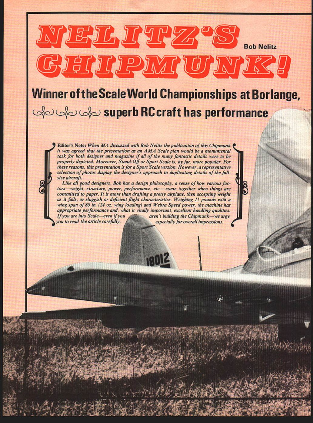
Winner of the Scale World Championships at Borlange, superb RC craft has performance
Editor's Note: When MA discussed with Bob Nelitz the publication of this Chipmunk it was agreed that the presentation as an AMA Scale plan would be a monumental task for both designer and magazine if all of the many fantastic details were to be properly depicted. Moreover, Stand-Off or Sport Scale is, by far, more popular. For these reasons, this presentation is for a Sport Scale version. However, a representative selection of photos display the designer's approach to duplicating details of the full-size aircraft.
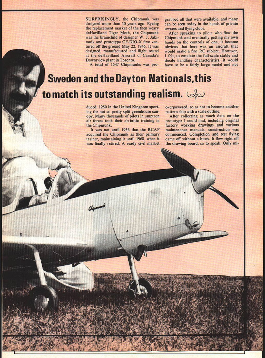
Like all good designers, Bob has a design philosophy, a sense of how various factors—weight, structure, power, performance, etc.—come together when things are committed to paper. It is more than drafting a pretty airplane, then accepting weight as it falls, or sluggish or deficient flight characteristics. Weighing 11 pounds with a wing span of 86 in. (24 oz. wing loading) and Webra Speed power, the machine has appropriate performance and, what is vitally important, excellent handling qualities. If you are into Scale—even if you aren't building the Chipmunk—we urge you to read the article carefully, especially for overall impressions. SURPRISINGLY, the Chipmunk was designed more than 30 years ago. Eyeing the replacement market of the then weary de Havilland Tiger Moth, the Chipmunk was the brainchild of designer W. J. Jakimuk and prototype CF-DIO-X first ventured off the ground May 22, 1946. It was designed, manufactured and flight tested at the de Havilland Aircraft of Canada's Downsview plant in Toronto.
Sweden and the Dayton Nationals, this to match its outstanding realism.
A total of 1547 Chipmunks was produced, 1250 in the United Kingdom sporting the not so pretty split greenhouse canopy. Many thousands of pilots in umpteen air forces took their ab‑initio training in the Chipmunk.
It was not until 1956 that the RCAF acquired the Chipmunk as their primary trainer, maintaining it until 1968, when it was finally retired. A ready civil market grabbed all that were available, and many can be seen today in the hands of private owners and flying clubs.
After speaking to pilots who flew the Chipmunk and eventually getting my own hands on the controls of one, it became obvious that here was an aircraft that would make a fine RC subject. However, I felt, to emulate the full‑scale stable and docile handling characteristics, it would have to be a fairly large model and not overpowered, so as not to become another pattern ship with a scale outline.
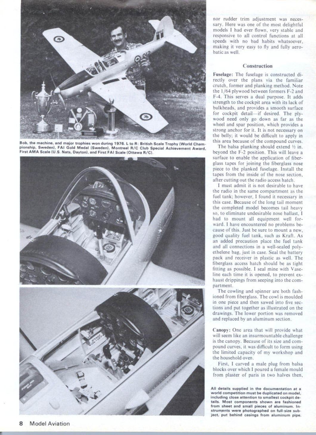
After collecting as much data on the prototype I could find, including original factory working drawings and various maintenance manuals, construction was commenced. Completion and test flying came off without a hitch. It flew right off the drawing board, so to speak. Only mi- nor rudder trim adjustment was necessary. Here was one of the most delightful models I had ever flown, very stable and responsive to all control functions at all speeds with no bad habits whatsoever, making it very easy to fly and fully aerobatic as well.
Construction
Fuselage:
The fuselage is constructed directly over the plans via the familiar crutch, former and planking method. Note the 1/64 plywood between formers F‑2 and F‑4. This serves a dual purpose. It adds strength to the cockpit area with its lack of bulkheads, and provides a smooth surface for cockpit detail — if desired. The plywood need only go down as far as the wheel and spar position, which provides a strong anchor for it. It is not necessary on the belly; it would be difficult to apply in this area because of the compound curves.
The balsa planking should extend 1/2 in. beyond the F‑2 position. This will leave a surface to enable the application of fiberglass tapes for joining the fiberglass nose piece to the planked fuselage. Install the tapes from the inside of the nose section, after cutting out the radio access hatch.
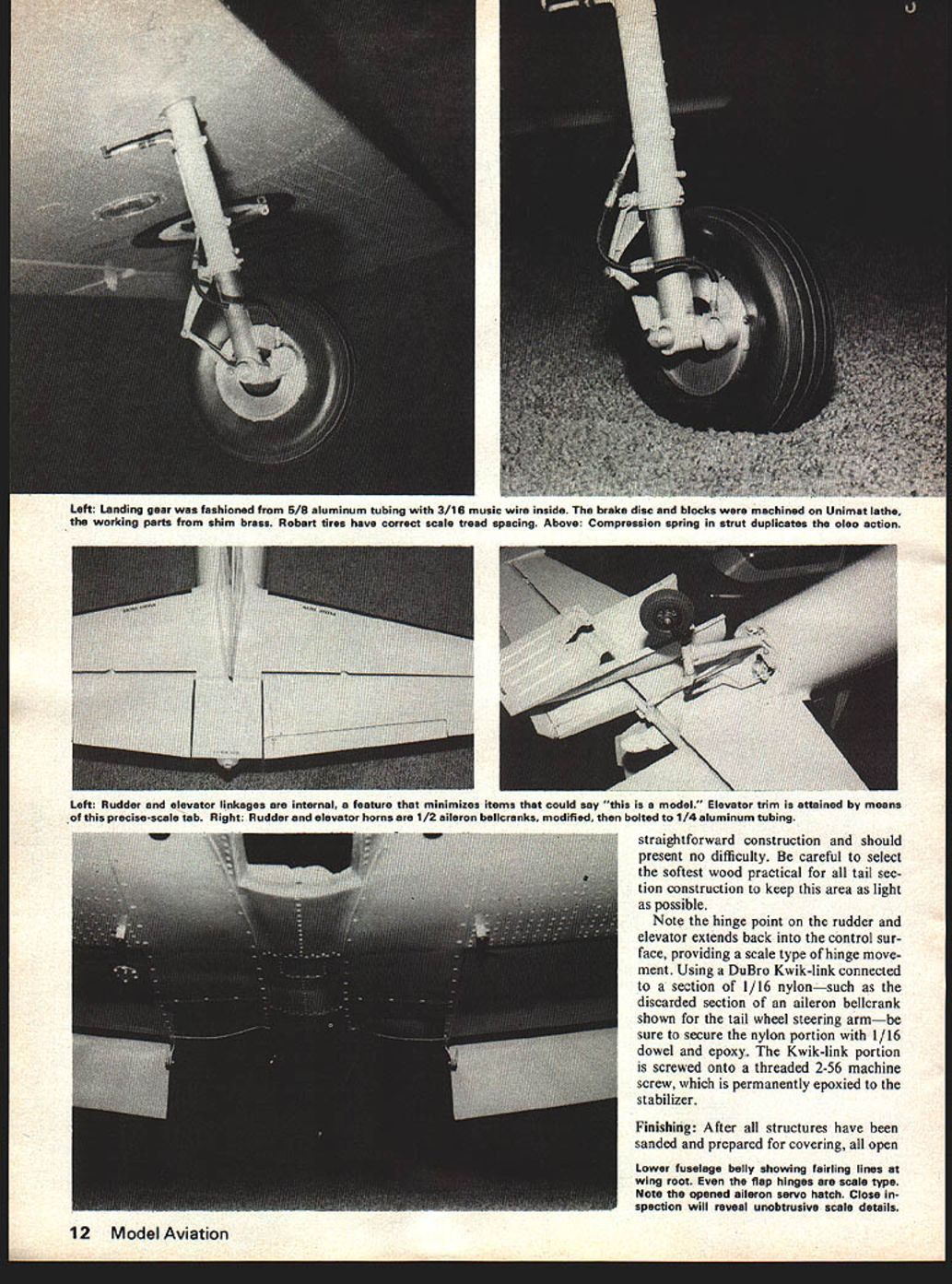
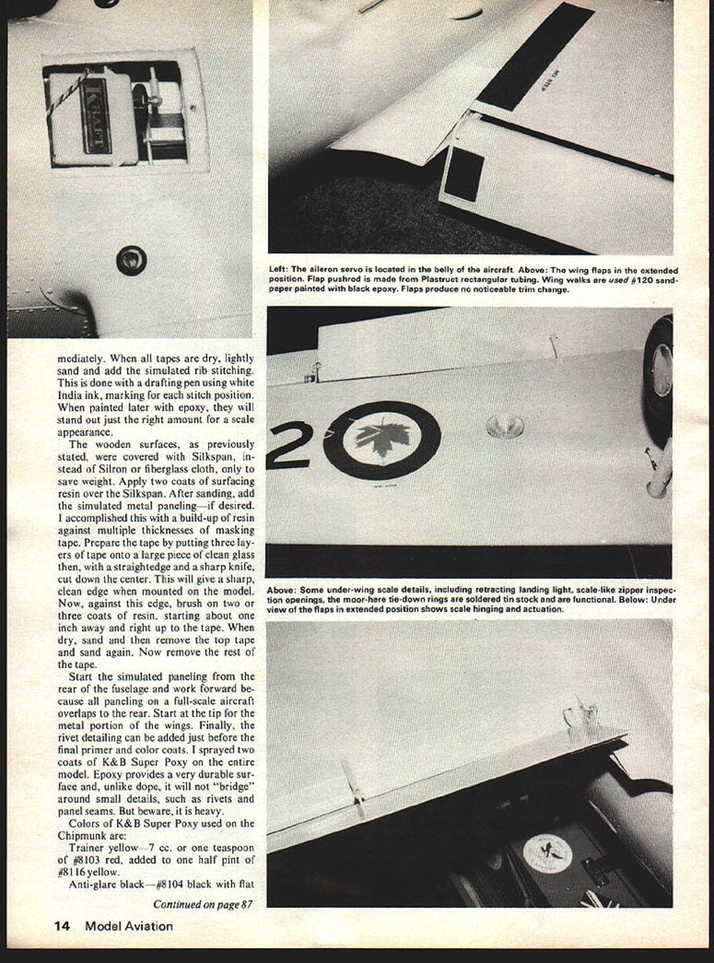
I must admit it is not desirable to have the radio in the same compartment as the fuel tank; however, I found it necessary in this case. Because of the long tail moment the completed model becomes tail heavy so, to eliminate undesirable nose ballast, I had to mount all equipment well forward. I have encountered no problems because of this. Just be sure to mount a new, good quality fuel tank, such as Kraft. As an added precaution place the fuel tank and all connections in a well‑sealed polyethylene bag, just in case. Seal the battery pack and receiver in plastic as well. The fiberglass access hatch should be as tight fitting as possible. I seal mine with Vaseline each time it is opened, to prevent exhaust drippings from seeping into the compartment.
The cowling and spinner are both fashioned from fiberglass. The cowl is moulded in one piece and then sawed into five sections and put together as illustrated on the drawings. The lower portion was removed and replaced by an aluminum section.
Canopy:
One area that will provide what will seem like an insurmountable challenge is the canopy. Because of its size and compound curves, it was difficult to form using the limited capacity of my workshop and the household oven.
First, I carved a male plug from balsa blocks over which I poured a female mould from plaster of paris in two halves, then
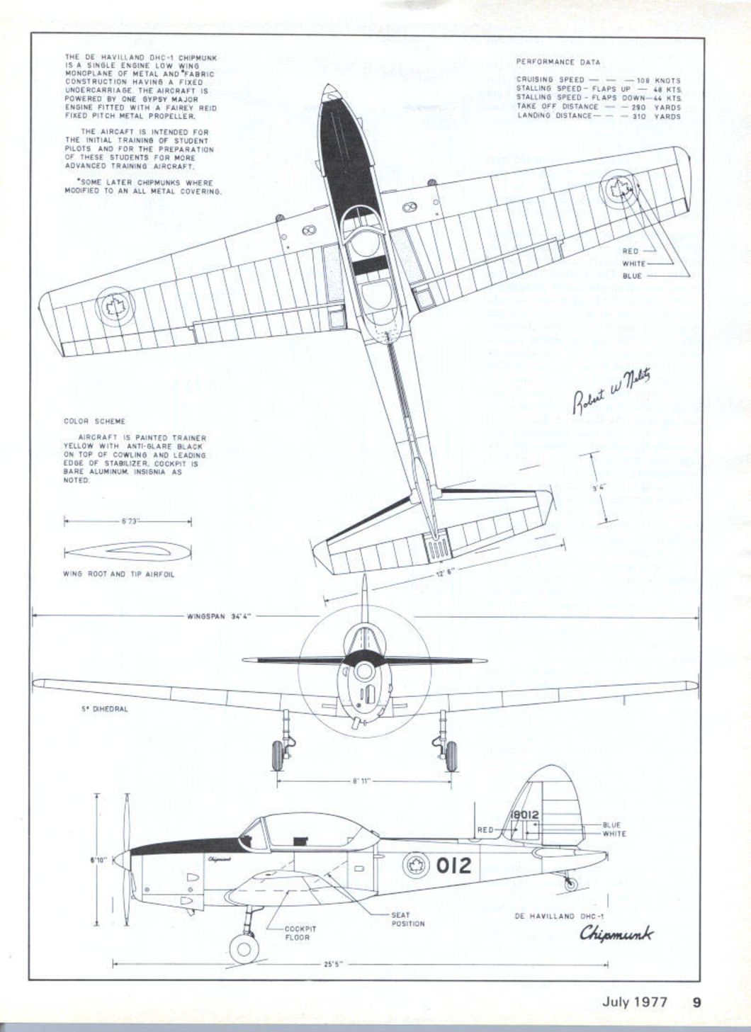
All details supplied in the documentation at a world competition must be duplicated on model, including close attention to smallest cockpit details. Most components shown are fashioned from sheet and small pieces of aluminum. Instruments were photographed on full‑size subject, put behind casings from aluminum pipe. The de Havilland DHC-1 Chipmunk is a single engine low wing monoplane of metal and fabric construction having a fixed undercarriage. The aircraft is powered by one Gypsy Major engine fitted with a Fairey Reid fixed pitch metal propeller.
The aircraft is intended for the initial training of student pilots and for the preparation of these students for more advanced training aircraft.
*Some later Chipmunks were modified to an all metal covering.
Color Scheme
Aircraft is painted trainer yellow with anti‑glare black on top of cowling and leading edge of stabilizer. Cockpit is bare aluminum. Insignia as noted.
Performance Data
- Cruising speed — 108 knots
- Stalling speed — flaps up — 48 kts
- Stalling speed — flaps down — 44 kts
- Take off distance — 290 yards
- Landing distance — 310 yards
From wood and metal, I then made a cover frame to pull the hot plastic down over the mould. I fashioned about a dozen canopies before I got one that was acceptable. I can offer two solutions to this problem. One is to locate a full‑size Chipmunk with the British split type canopy and copy it—which would be no problem, since it was constructed from flat pieces of Plexiglass. Or you may contact Bill Hempel of Hobby Barn in Tucson. He has offered to supply canopies on request, based on my original mould.
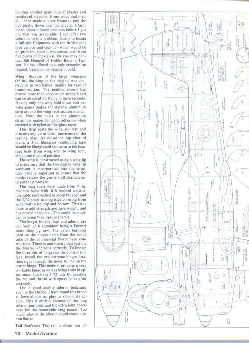
Wing
Because of the large wingspan (86 in.) the wing on the original was constructed in two halves, mainly for ease of transportation. The method shown has proved more than adequate in strength and can be attached for flying in mere seconds. Having only one wing hold‑down bolt per wing panel makes the narrow aluminum strip around the wing root section mandatory. Note the holes in the aluminum strip; this makes for good adhesion when covered with nylon or fiberglass tapes.
This strip seats the wing securely and prevents any up or down movement of the trailing edge. As shown on top view of plans, a 3‑in. fiberglass reinforcing tape should be fiberglassed spanwise to the fuselage belly from wing root to wing root, about center chord position.
The wing is constructed using a wing jig to make sure that the two degree wing tip wash‑out is incorporated into the structure. This is important to ensure that the model retains the gentle stall characteristics of the prototype.
The wing spars were made from 1/4 sq. medium balsa with .018 braided control‑line cable sandwiched between the spar and the 3/32‑sheet leading edge covering from wing root to tip, top and bottom. This was done to add strength and save weight, and has proved adequate. (This could be modified by using 1/4 sq. spruce spars.)
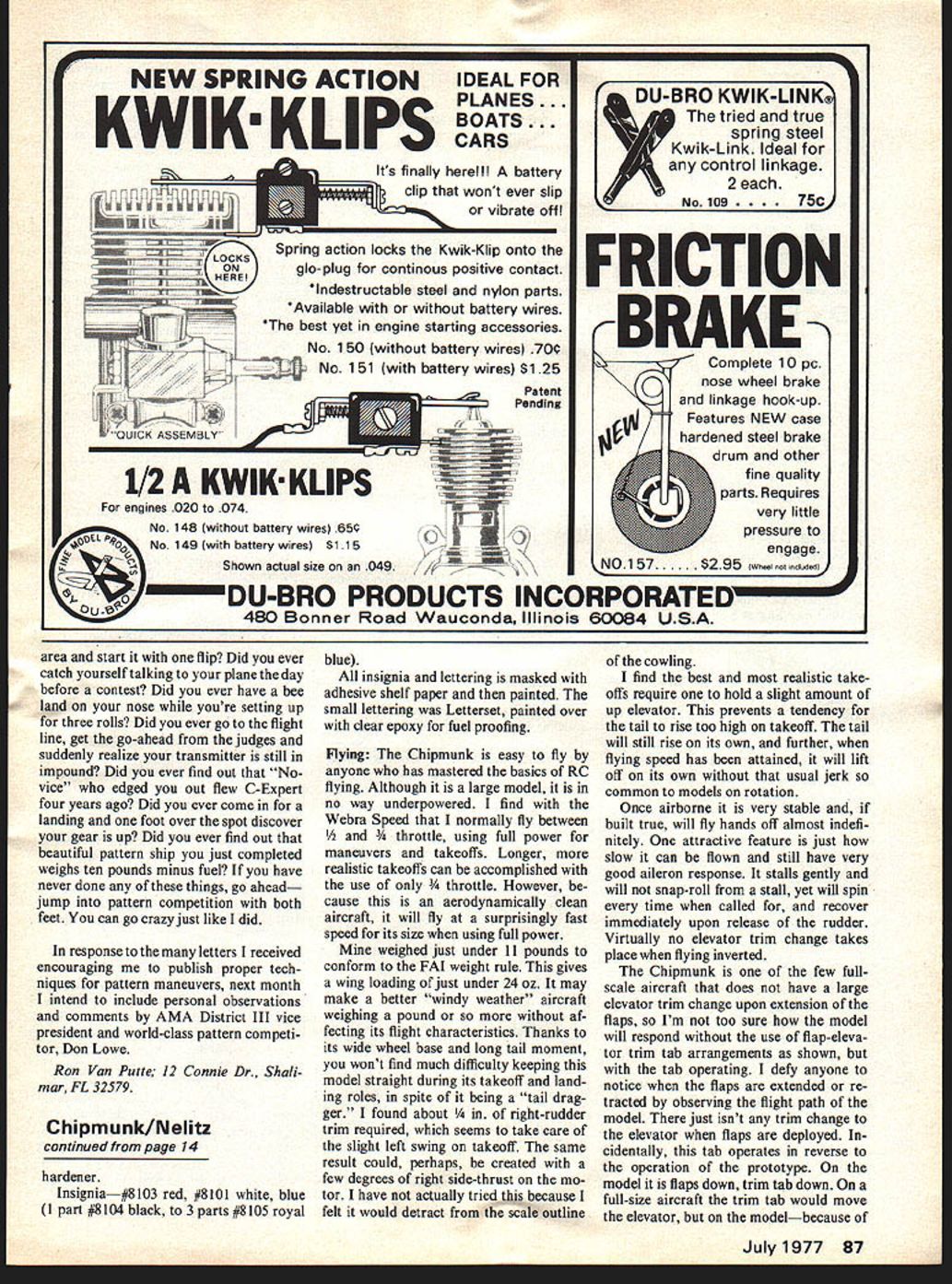
The hinges for the flaps and aileron are cut from 1/16 aluminum using a Dremel moto‑shop jig saw. The nylon bushings used on the hinges came from the inside tube of the commercial Nyrod type control rods. There is one variety that just fits the Morris 1‑72 bolts perfectly. To line up the three sets of hinges on the control surface, install the two extreme hinges first, then sight through the holes to line up the center hinge. This method provides a very workable hinge as well as being scale in appearance. Lock the 1‑72 nuts by painting the nut and thread with epoxy paint after assembly.
Use a good quality aileron bellcrank such as the DuBro. I have found this brand to have almost no play or slop in its action. This is critical because of the long aileron pushrods and the extra joint necessary for the removable wing panels. Too much play in the aileron could cause aileron flutter.
Tail Surfaces
The tail surfaces are of Tail Surfaces The tail surfaces are of built-up construction as shown on the plans.
Construction
Fuselage
The fuselage is constructed directly over the plans via the familiar crutch/former/planking method. Note: 1/64" plywood between formers F-2 and F-4 serves a dual purpose — it adds strength in the cockpit area and, because of its lack of bulkheads, provides a smooth surface. If cockpit detail is desired the plywood need not go down as far. The wheel-spar position provides a strong anchor; the necessary belly would be difficult to apply because of compound curves. Balsa planking should extend to the F-2 position; this will leave a surface to enable application of fiberglass tapes joining the fiberglass nose piece. Plank the fuselage and install the tapes inside the nose section after cutting out the radio-access hatch.
It must be admitted desirable to have the radio in the same compartment as the fuel tank; however, I found this was necessary in my case. Because of the long tail moment the completed model becomes tail heavy; to eliminate undesirable nose ballast, mount equipment well forward. I have encountered no problems as a result. Just be sure to mount a new, good-quality fuel tank such as Kraft. As an added precaution, place the fuel-tank connections in a well-sealed polyethylene bag, just in case. Seal the battery pack and receiver in plastic or with fiberglass. The access hatch should be as tight-fitting as possible; seal with Vaseline at the time of closing to prevent exhaust drippings from seeping into the compartment.
Cowling and spinner are both fashioned of fiberglass. The cowl is a molded piece sawed into five sections and put together as illustrated in the drawings; the lower portion is removed and replaced with an aluminum section.
Canopy
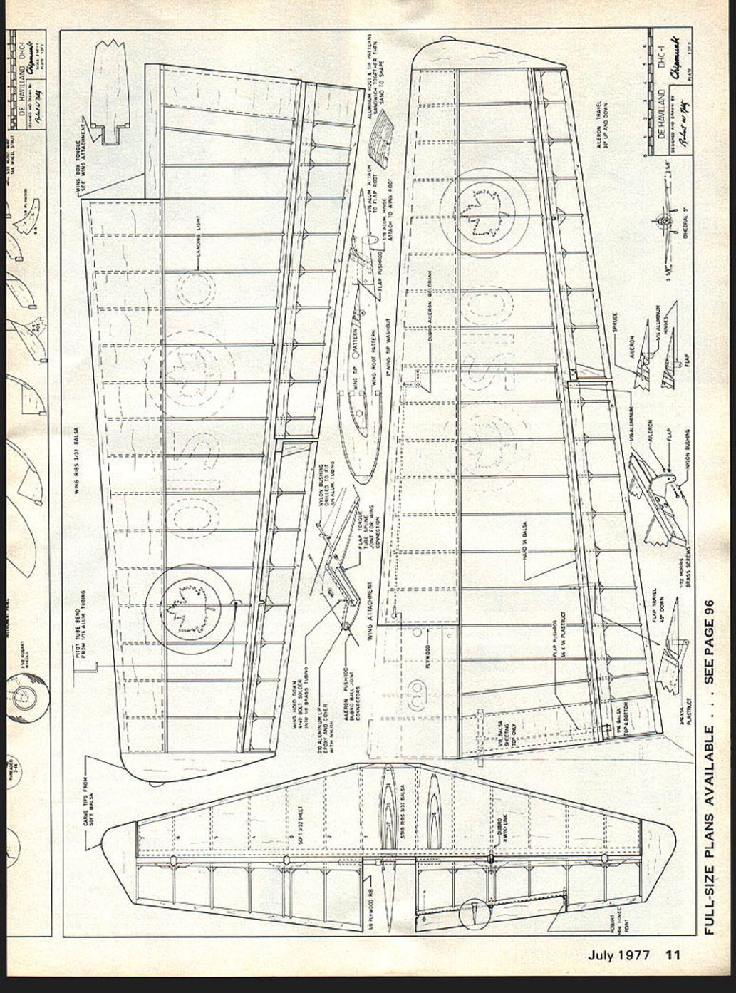
One area that will seem an insurmountable challenge is the canopy. Because of its size and compound curves it is difficult to form using a limited-capacity household oven. First carve a male plug from balsa blocks, then pour the female mold in plaster of Paris in two halves. Details are supplied in the documentation. For world competition the canopy must be duplicated on the model, including close attention to the smallest cockpit details. Most components shown are fashioned from sheet and small pieces; aluminum instruments are photographed from the full-size subject and put behind casings. Left: Landing gear was fashioned from 5/8 aluminum tubing with 3/16 music wire inside. The brake disc and blocks were machined on Unimat lathe, the working parts from shim brass. Robart tires have correct scale tread spacing. Above: Compression spring in strut duplicates the oleo action.
Left: Rudder and elevator linkages are internal, a feature that minimizes items that could say "this is a model." Elevator trim is attained by means of this precise-scale tab. Right: Rudder and elevator horns are 1/2 aileron bellcranks, modified, then bolted to 1/4 aluminum tubing.
Straightforward construction and should present no difficulty. Be careful to select the softest wood practical for all tail section construction to keep this area as light as possible.
Note the hinge point on the rudder and elevator extends back into the control surface, providing a scale type of hinge movement. Using a DuBro Kwik-link connected to a section of 1/16 nylon—such as the discarded section of an aileron bellcrank shown for the tail wheel steering arm—be sure to secure the nylon portion with 1/16 dowel and epoxy. The Kwik-link portion is screwed onto a threaded 2-56 machine screw, which is permanently epoxied to the stabilizer.
Finishing: After all structures have been sanded and prepared for covering, all open
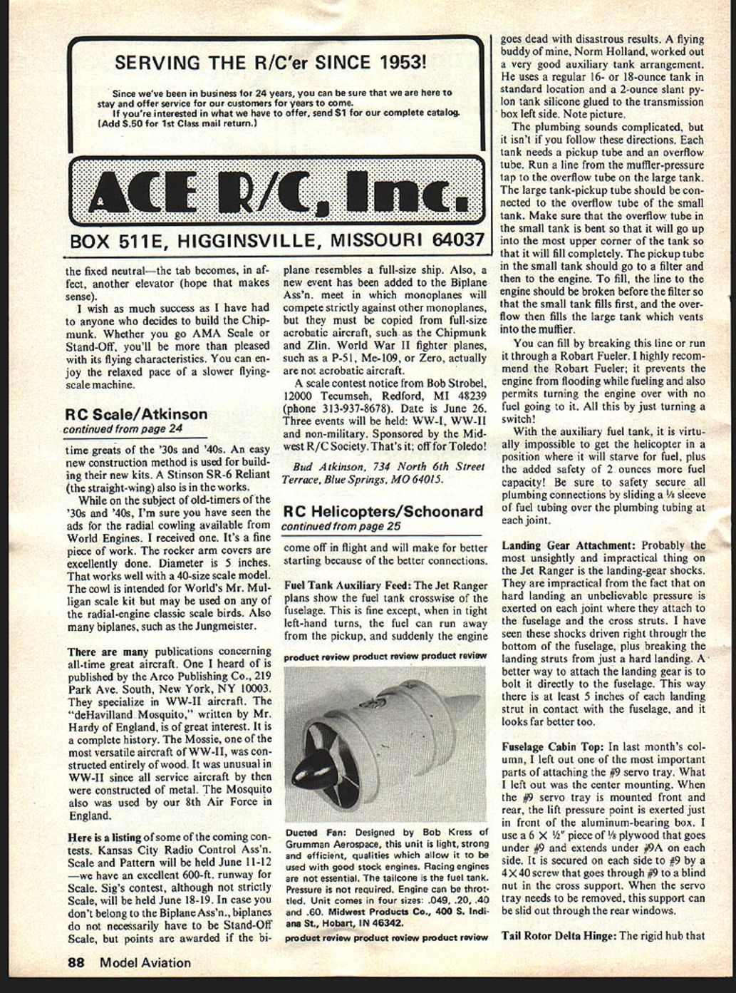
Lower fuselage belly showing fairing lines at wing root. Even the flap hinges are scale type. Note the opened aileron servo hatch. Close inspection will reveal unobtrusive scale details. structures are covered with Silron, with heavy Silkspan used over wooden structures, such as fuselage, fin and stabilizer. I applied them with nitrate dope. Nitrate has superior adhesion qualities in comparison to butyrate and, most important, it permits the use of resin and epoxy paints over it without curing problems.
To allow the weave of the Silron to show through the finish, simulating the prototype fabric covering on wings, elevator and rudder, use only four coats of nitrate dope, one coat of K&B primer, and two color coats. After three coats of clear, apply one coat of silver. The silver is necessary for a solid opaque finish color, preventing the wing-structure silhouette when flying overhead against a bright sunny background.
After the silver has been light sanded, add the rib tapes over all ribs, trailing edges and against the wing tip blocks—if desired. This is the method I used for making rib tapes. I pre-doped Silkspan over a wooden frame, three coats on each side. Then I stripped this into tapes using a serrated edge from an aluminum foil box. Be sure to tear the tapes across the grain of the Silkspan, otherwise a sharp, clean edge will be impossible. The tapes are then dipped in dope thinner and applied to the rib locations. Be certain to place the stripped tapes in the correct position on the first try, because they will stick almost immediately.
Canopy
One area will provide what will seem like an insurmountable challenge—the canopy. Because its size and compound curves make it difficult to form using a limited-capacity workshop household oven, first carve a male plug from balsa blocks and pour a female mould in plaster of Paris in two halves. Details supplied in the documentation for the world-competition model must be duplicated on the model, including close attention to the smallest cockpit details. Most components shown are fashioned from sheet and small pieces of aluminum; instruments photographed on the full-size subject were put behind casings of aluminum pipe. Immediately. When all tapes are dry, lightly sand and add the simulated rib stitching. This is done with a drafting pen using white India ink, marking for each stitch position. When painted later with epoxy, they will stand out just the right amount for a scale appearance.
The wooden surfaces, as previously stated, were covered with Silkspan, instead of Silron or fiberglass cloth, only to save weight. Apply two coats of surfacing resin over the Silkspan. After sanding, add the simulated metal paneling—if desired. I accomplished this with a build-up of resin against multiple thicknesses of masking tape. Prepare the tape by putting three layers of tape onto a large piece of clean glass then, with a straightedge and a sharp knife, cut down the center. This will give a sharp, clean edge when mounted on the model. Now, against this edge, brush on two or three coats of resin, starting about one inch away and right up to the tape. When dry, sand and then remove the top tape and sand again. Now remove the rest of the tape.
Start the simulated paneling from the rear of the fuselage and work forward because all paneling on a full-scale aircraft overlaps to the rear. Start at the tip for the metal portion of the wings. Finally, the rivet detailing can be added just before the final primer and color coats. I sprayed two coats of K & B Super Poxy on the entire model. Epoxy provides a very durable surface and, unlike dope, it will not "bridge" around small details, such as rivets and panel seams. But beware, it is heavy.
Colors of K & B Super Poxy used on the Chipmunk are:
- Trainer yellow — 7 cc. or one teaspoon of #8103 red, added to one half pint of #8116 yellow.
- Anti-glare black — #8104 black with flat
hardener.
Insignia — #8103 red, #8101 white, blue (1 part #8104 black to 3 parts #105 royal blue).
All insignia and lettering is masked with adhesive shelf paper and then painted. The small lettering was Letterset, painted over with clear epoxy for fuel proofing.
Flying: The Chipmunk is easy to fly by anyone who has mastered the basics of RC flying. Although it is a large model, it is in no way underpowered. I find with the Webra Speed that I normally fly between 1/2 and 3/4 throttle, using full power for maneuvers and takeoffs. Longer, more realistic takeoffs can be accomplished with the use of only 1/4 throttle. However, because this is an aerodynamically clean aircraft, it will fly at a surprisingly fast speed for its size when using full power.
Mine weighed just under 11 pounds to conform to the FAI weight rule. This gives a wing loading of just under 24 oz. It may make a better "windy weather" aircraft weighing a pound or so more without affecting its flight characteristics. Thanks to its wide wheel base and long tail moment, you won't find much difficulty keeping this model straight during its takeoff and landing rolls, in spite of it being a "tail dragger." I found about 1/8 in. of right-rudder trim required, which seems to take care of the slight left swing on takeoff. The same result could, perhaps, be created with a few degrees of right side-thrust on the motor. I have not actually tried this because I felt it would detract from the scale outline of the cowling.
I find the best and most realistic takeoffs require one to hold a slight amount of up elevator. This prevents a tendency for the tail to rise too high on takeoff. The tail will still rise on its own, and further, when flying speed has been attained, it will lift off on its own without that usual jerk so common to models on rotation.
Once airborne it is very stable and, if built true, will fly hands off almost indefinitely. One attractive feature is just how slow it can be flown and still have very good aileron response. It stalls gently and will not snap-roll from a stall, yet will spin every time when called for, and recover immediately upon release of the rudder. Virtually no elevator trim change takes place when flying inverted.
The Chipmunk is one of the few full-scale aircraft that does not have a large elevator trim change upon extension of the flaps, so I'm not too sure how the model will respond without the use of flap-elevator trim tab arrangements as shown, but with the tab operating, I defy anyone to notice when the flaps are extended or retracted by observing the flight path of the model. There just isn't any trim change to the elevator when flaps are deployed. Incidentally, this tab operates in reverse to the operation of the prototype. On the model it is flaps down, trim tab down. On a full-size aircraft the trim tab would move the elevator, but on the model—because of the fixed neutral — the tab becomes, in effect, another elevator (hope that makes sense).
I wish as much success as I have had to anyone who decides to build the Chipmunk. Whether you go AMA Scale or Stand-Off, you'll be more than pleased with its flying characteristics. You can enjoy the relaxed pace of a slower flying-scale machine.
THE DE HAVILLAND DHC-1 CHIPMUNK — PERFORMANCE DATA IS SINGLE ENGINE LOW WING MONOPLANE OF METAL AND FABRIC
CRUISING SPEED 8 KNOTS
CONSTRUCTION HAVING FIXED
STALLING SPEED, FLAPS UP 48 KTS
UNDERCARRIAGE THE AIRCRAFT IS
STALLING SPEED, FLAPS DOWN 44 KTS
POWERED BY ONE GYPSY MAJOR
TAKE OFF DISTANCE YARDS
ENGINE FITTED WITH FAIREY REI
Transcribed from original scans by AI. Minor OCR errors may remain.

