
Nesmith Cougar
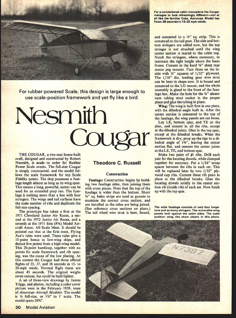
For rubber-powered Scale, this design is large enough to use scale-position framework and yet fly like a bird.
Theodore C. Russell
Construction
#### Fuselage Construction begins by building two fuselage sides, then joining them with cross pieces. Note that the top of the fuselage is wider than the bottom. Short 1/8" sq. balsa strips are used as gussets to maintain the correct cross section, and are installed as the sides are being joined. (See reference cross sections on plans.) The tail wheel wire strut is bent, bound, and cemented to a 1/8" sq. strip. This is cemented to the tail post. The side and bottom stringers are added now, but the top stringer is not attached until the wing center section is mated to the cabin top. Notch the stringers, where necessary, to maintain the right height above the basic frame. Cement in the hard 1/8" sheet rear motor peg mounts. Face these on the inside with 1/2" squares of 1/32" plywood. The 1/16" dia. landing gear wire strut can be bent to shape now. It is bound and cemented to the LG mount, and the whole assembly is glued to the front of the fuselage box. Make the hole for the 1/4" aluminum tubing strut socket in the proper place and glue the tubing in place.
#### Wing The wing is built first in one piece, with the dihedral angle built in. After the center section is cemented to the top of the fuselage, the wing panels are cut loose. Lay LE, bottom spar, and TE on the plan, and cement in all the ribs, except at the dihedral joints. Glue in the top spar, except at the dihedral breaks. When the framework is dry, prop up the tips to a dihedral angle of 1 3/8", leaving the center section flat, and cement the center joints at the LE, TE, and bottom spar.
Make two pairs of #1 ribs. Drill each pair for the locating dowels, while clamped together for accuracy. Put a 1/16" scrap spacer between the ribs in each set. This will be replaced later by two 1/32" plywood cap ribs. Cement rib pairs in place at the dihedral breaks. Glue the locating dowels solidly to the center section rib inside rib set. Now finish up the top spar.
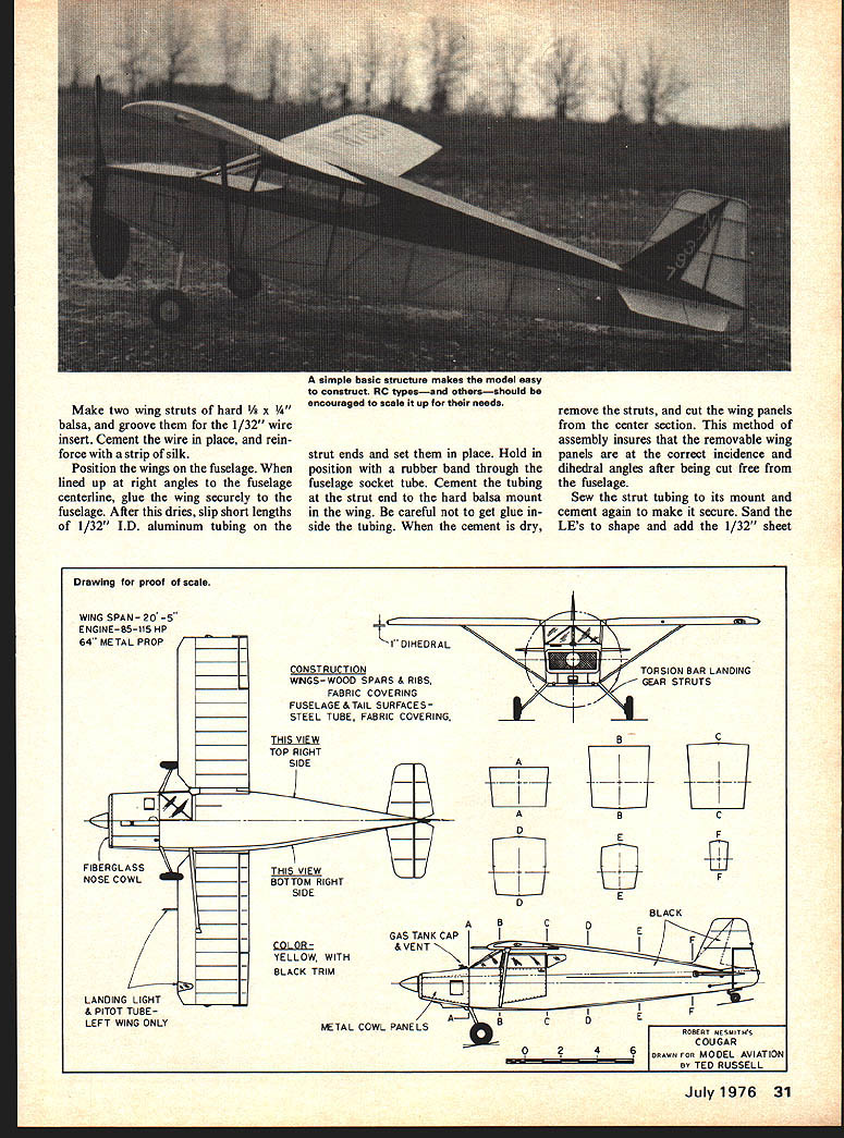
Make two wing struts from hard 3/16" x 1/4" balsa, groove for 1/32" wire insert. Cement the wire in place and cement a reinforcing strip of silk. Position wings on fuselage lined up at right angles to the fuselage centerline and glue wing securely to fuselage. After it dries, slip short lengths of 1/32" I.D. aluminum tubing over the strut ends to set in place. Hold position with a rubber band through the fuselage socket tube. Cement the tubing strut end to the hard balsa mount on the wing; be careful to get glue on the side of the tubing. When cement is dry, remove struts and cut the wing panels from the center section. This method of assembly insures removable wing panels with correct incidence and dihedral angles after being cut free from the fuselage. Slip the strut tubing into its mount, cement again and make secure. Sand LEs to shape and add 1/32" sheet as required. balsa from the top spar forward. The 1/32" ply cap ribs should be added now at the tips, roots, and to the center section on
Brush on one coat of clear dope. Now cut the license numbers, side fuselage, and rudder color patterns, from black tissue. Attach these in the proper positions with straight thinner. Brush two more coats of half dope, half thinner, on the fuselage and wings, and one coat on the tail surfaces.
Install the 1/16" and 1/8" cabin windshield dowels. Dope the 1/16" dowels silver, and the 1/8" dowels black. Make the windshield of heavy celluloid, and side windows of light celluloid. Use tissue strips over the balsa window framework. Add a black tissue strip to the center of the windshield, also.
Make landing gear struts of hard balsa. Groove the struts and cement to the landing gear wire. Reinforce with a strip of silk, and cover with yellow tissue. Also, cover the wing struts with yellow tissue. Make the air intake, cover with tissue, and mount in position. Make exhaust stacks, dope flat black, and mount. Line up the stab in the fuselage slot, making sure it is straight, and cement in place. Cement the fin in position, again making sure it is straight.
Bend the prop shaft from 1/16" dia. wire, with a winding hook on the front. Put a flat washer, a ball-bearing washer, and another flat washer, between the propeller and the nose block. Make the wheels from hard 1/16" sheet, laminated cross-grain. Install bushings for the axles and fill the grain with sanding sealer. Dope the tires flat black, and the hubs yellow. Install the main wheels with soldered washers (#0 brass washers from the model railroad department). Cement the tail wheel directly to the wire strut. It does not revolve.
Put the wing struts in place with short rubber bands through the fuselage tube. Attach the wings with short rubber bands through the center section paper tube, and slip the wire strut ends into the tubing on the wings.
Make up a motor of six strands of Pirelli rubber, 20 to 24" long. Install the motor and check the model's balance. It should balance about 9/16" in front of the main spar. Add weight to nose or tail to get the indicated balance point. Mine took just a small amount of nose weight. Hand glide over tall grass to make sure there is no bad stall or dive. If there is, add weight at the appropriate place to cure it. Start with a few winds and slowly increase power. Shim the nose block for side or down-thrust to keep away from a power stall. Use the hinged rudder for glide turn. Make final weight adjustments for a flat glide.
The original had a wide right power circle and turned to the left in the glide. It could probably turn to the right in the glide, too. If so, put a slight amount of wash-in in the right wing panel. You may have to use eight strands of rubber in windy conditions to punch through the turbulence and get altitude. The model is very steady in the wind.
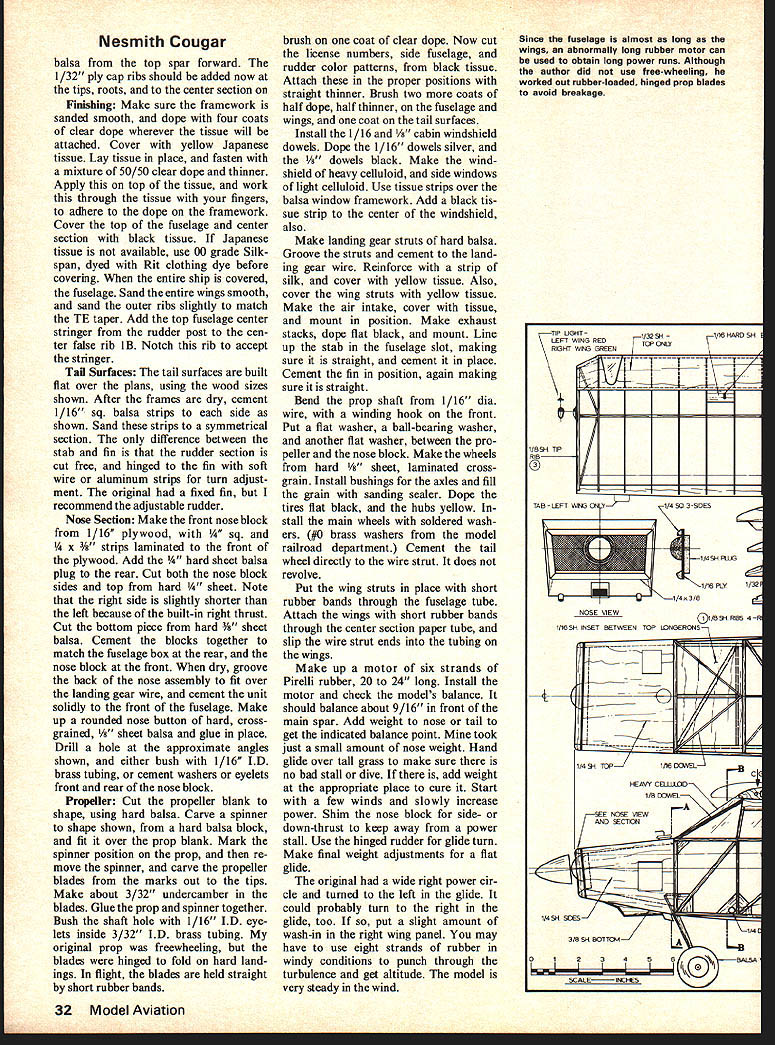
Since the fuselage is almost as long as the wings, an abnormally long rubber motor can be used to obtain long power runs. Although the author did not use free-wheeling, he worked out rubber-loaded, hinged prop blades to avoid breakage.
Nesmith Cougar
The Cougar, a two-seat home-built craft designed and constructed by Robert Nesmith, was made for rubber-power scale events. The full-size Cougar is simply constructed and the model follows the scale framework. In scale-fidelity points the ship possesses a fuselage almost as long as its wing span, which means a long, powerful motor can be used for extended prop run. The fuselage is nothing more than a box of four stringers; the wings and tail surfaces have the scale number of ribs duplicated at full-size spacing.
The prototype has taken first at the 1971 Cleveland Junior Air Races, second at the 1972 Junior Air Races and seventh at the 1971 Erie, Pa., Model Aircraft Assoc. Scale Meet. It should be pointed out that the Erie meet used Flying Aces rules. These rules give a 15-point bonus to low-wing ships and a 20-point handicap to high-wing models; together such scoring can affect placing in a contest.
The Cougar made three official flights of 35, 37 and 38 seconds in 15–20 mph winds. Normal flight times are about 45 seconds. The original weighs seven ounces but could be built lighter. A set of three-view drawings by James Triggs and photos, including the color cover picture, appeared in the February 1959 issue of American Aircraft Modeler.
Construction
Fuselage Construction begins by building two fuselage sides and joining them with cross pieces. Note the top of the fuselage is wider than the bottom. Short balsa strips are used as gussets to maintain the correct cross section while the sides are being joined. See the reference cross sections on the plans.
The tail-wheel wire strut is bent and bound in the conventional cabin-monoplane manner. The Cougar manages to look refreshingly different — not like the familiar Cubs and Aeroncas. Cement a 1/8 sq. strip and cement the tail post. Side bottom stringers are added, then the top stringer is attached until the wing center section is mated to the cabin top. Notch stringers as necessary to maintain the right height above the basic frame.
Cement a hard sheet rear motor peg mount. Face the sides with 1/32 plywood. A 1/16 dia. landing-gear wire strut can be bent to shape, now bound and cemented to the LG mount. The whole assembly is glued to the front fuselage box. Make a hole in a short length of aluminum tubing for the strut socket in the proper place and glue the tubing in place.
Wing The wing is built as the first piece; the dihedral angle is built in after the center section is cemented to the top fuselage. Lay the leading-edge (LE), bottom spar and trailing-edge (TE) on the plan. Cement ribs except at the dihedral joints. Glue the top spar except at the dihedral breaks. Dry-prop up the tips to the dihedral angle (1/8"), leaving the center section flat, and cement the center joints, LE, TE and bottom spar.
Make two pairs of No. 1 ribs. Drill a pair of locating dowels and clamp the ribs together for accuracy. Put a 1/16" scrap spacer between the ribs (this will be replaced later) and fit two 1/32" ply cap ribs. Cement the rib pairs in place at the dihedral breaks. Glue the locating dowels solidly into the center section rib inside the rib set. Now finish up the top spar.
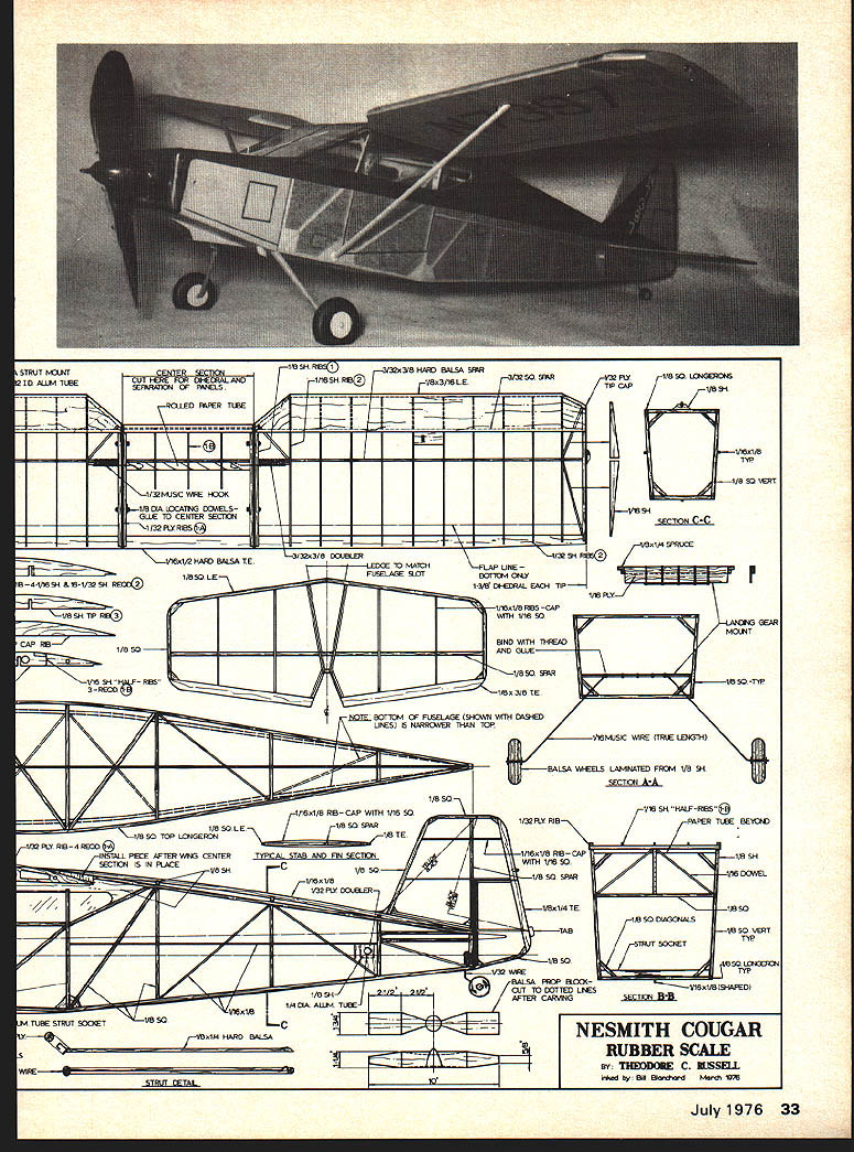
The wide fuselage consists of four longerons and stringers. Removable wing panels butt against the cabin sides; the scale-position wing ribs show clearly in the photo. Make two wing struts from hard 3/8" x 1/4" balsa with a groove for a 1/32" wire insert. Cement the wire in place and reinforce with a strip of silk.
Position the wings on the fuselage, aligned at right angles to the fuselage centerline, and glue the wing securely to the fuselage. After the glue dries, slip short lengths of 1/32" I.D. aluminum tubing over the strut ends and set them in place. Hold the position with a rubber band through the fuselage socket tube. Cement the tubing to the strut end and cement a hard-balsa mount on the wing. Be careful to get the glue on the side of the tubing; when the cement is dry remove the struts and cut the wing panels free of the center section. This method of assembly insures removable wing panels with correct incidence and dihedral angles after being cut free from the fuselage. Sew the strut tubing to its mount, cement again and make secure.
Sand the leading edges to shape and add 1/32" sheet as required.
Transcribed from original scans by AI. Minor OCR errors may remain.

