
Nesmith Cougar
Julie M. Abel
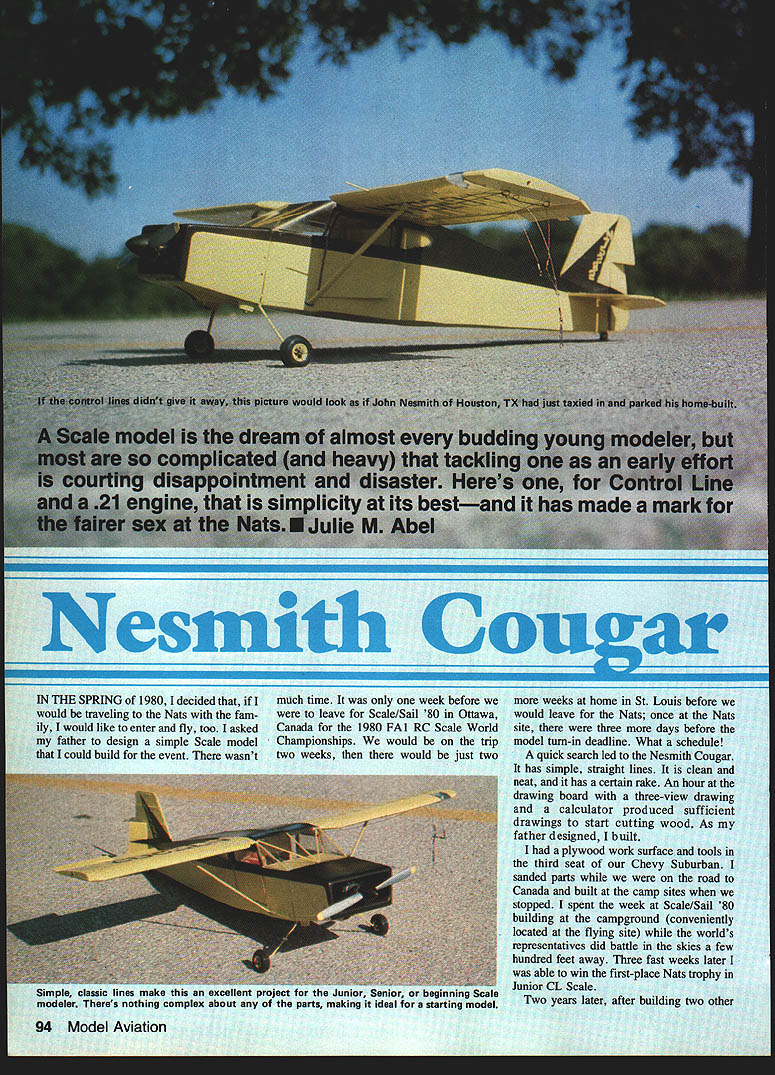
A scale model is the dream of almost every budding young modeler, but most are so complicated (and heavy) that tackling one as an early effort is courting disappointment and disaster. Here's one, for control line and a .21 engine, that is simplicity at its best—and it has made a mark for the fairer sex at the Nats.
In the spring of 1980, I decided that, if I would be traveling to the Nats with the family, I would like to enter and fly, too. I asked my father to design a simple scale model that I could build for the event. There wasn't much time. It was only one week before we were to leave for Scale/Sail '80 in Ottawa, Canada, for the 1980 FAI RC Scale World Championships. We would be on the trip two weeks, then there would be just two more weeks at home in St. Louis before we would leave for the Nats; once at the Nats site there were three more days before the model turn-in deadline. What a schedule!
A quick search led to the Nesmith Cougar. It has simple, straight lines — clean and neat, with a certain rake. An hour at the drawing board with a three-view drawing and a calculator produced sufficient drawings to start cutting wood. As my father designed, I built.
I sanded parts while we were on the road and built at the camp sites when we stopped. I spent the week at Scale/Sail '80 building at the campground while the world's representatives did battle in the skies a few hundred feet away. Three fast weeks later I was able to win the first-place Nats trophy in Junior CL Scale.
There's nothing complex about the parts, making the Cougar an excellent project for the junior or senior beginning scale builder.
Fuselage construction
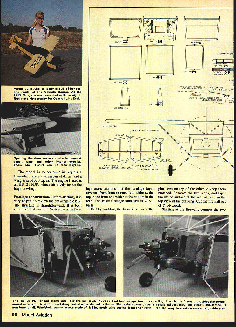
Before starting, review the drawings closely. The fuselage structure is straightforward — both strong and lightweight. Note the fuselage cross sections: the taper reverses from front to rear (wider on top at the front, wider on the bottom at the rear). The basic fuselage structure uses 1/4-in. square balsa.
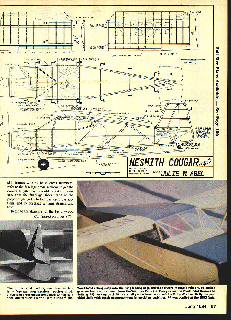
Start building the basic sides over the plan. Pin the top of each side and keep the two sides matched. The two sides taper on the inside surface at the rear as seen in the top-view drawing. Cut the firewall from 1/4-in. plywood. Beginning with the firewall, connect the two sides, using 1/4-in. balsa cross members for the side frames (refer to the fuselage cross sections for correct lengths). Take care to assure that the fuselage sides stand at the proper angle and that the fuselage remains straight and true.
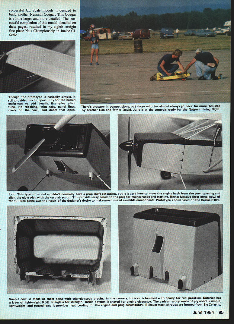
A plywood fuel-tank compartment extending through the firewall provides a proper mount for the HB .21 (PDP) engine, which looks small in the big cowl. A short length of brass tubing, silver-soldered, carries the muffled exhaust out through the scale exhaust pipe; the other exhaust stack is nonfunctional. The engine mount and fuel tank tray consist of a box of 1/4-, 1/16-, and 1/8-in. plywood assembled and epoxied onto the firewall. A radial engine mount is bolted to the front of the box.
Windshield corner braces are made from 1/8-in. music wire and extend from the firewall to the wing, creating a very strong cabin area. The music wire is attached to the firewall using landing-gear straps and wood screws and attached to the 1/8-in. plywood wing-root structure by tacking in place with a cyanoacrylate (CYA) adhesive (Jet, Hot Stuff, Zap, etc.).
Insert the 5/32-in. I.D. brass tubing through the 1/16-in. plywood wing-root attachment pieces; this tubing carries the 5/32-in. music-wire wing rod. Also insert the 1/16-in. I.D. tubing for the rear 1/16-in. music-wire wing rod. Add the 1/16-in. plywood bellcrank mount, laying it tightly on top of the music wire and fitted between the brass tubing carrying the wing rods, and epoxy it in place. Reinforce with 2-oz. fiberglass cloth and resin at the junction of the 1/8-in. music-wire windshield side former and the 1/8-in. plywood bellcrank mount. This technique ties the wing, landing gear, bellcrank mount, and firewall into a strong, rigid structure.
Refer to the drawings for pushrod layout and for aileron/elevon hardware. To keep the pushrod or wire from breaking out of the small aileron stock, add a small piece of 3/32-in. plywood, top and bottom, on each elevon where the hole is drilled. Use your favorite hinging technique.
The cowling is a 1/4-in. balsa box (3/32-in. balsa front) with a 1/16-in. plywood carb scoop added to the bottom. Reinforce the corners with 1/2-in. triangle balsa stock, sanded to the proper angle. After sanding the cowl to shape, cover the outside with one layer of 2-oz. fiberglass cloth and coat with epoxy resin inside and outside. Brush the interior with epoxy for fuel-proofing. Inside, shave the bottom for engine clearance. Exhaust-stack shrouds are formed from Sig Celastic.
Note: Complete the tail construction at this point, then return to final fuselage fairing and sheeting.
Final fuselage finishing
With the tail assemblies installed, the upper and lower fuselage fairings and side stringers can be added. The fuselage forward section aft of the cowling can now be sheeted with 1/16-in. balsa. Add the remaining fuselage items — window fairing, instrument panel, and doors.
Do not use ballast unless absolutely necessary; only 1 oz. of additional weight is an increase of more than 5% in the total model weight.
Tail assemblies
The vertical fin is assembled over the plan. Remove it from the plan and add the 1/16 x 1/8-in. balsa rib strips (two required at each location — refer to drawing section I-I). Attach the vertical fin to the aft fuselage with care to align it correctly.
Construct the horizontal surface over the plan, remove it, and place it through the aft fuselage. Add the remaining four pieces of 1/4-in. square balsa to the fuselage through the tail assembly. The rudder and elevator are conventional flat structures.
Wing
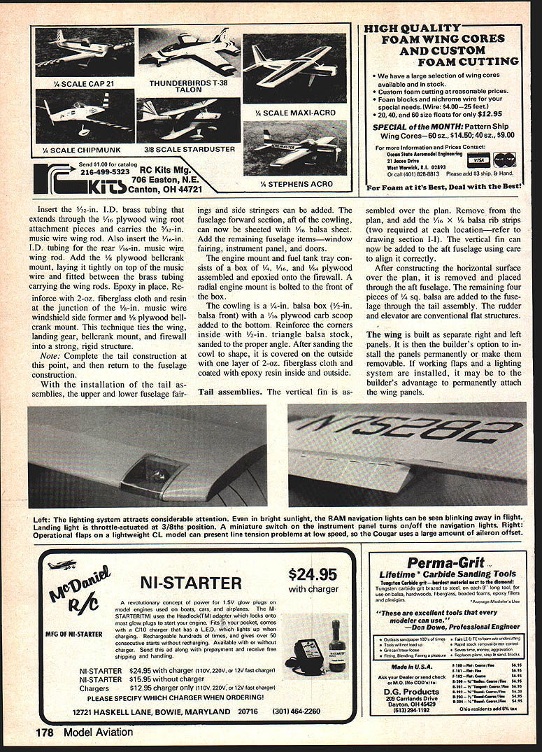
The wing is built as separate right and left panels. The builder may choose to install the panels permanently or make them removable; if working flaps and a lighting system are to be installed, permanent attachment may be advantageous.
Cover the wing with a low-temperature covering film directly over the foam. Cover the rudders and attach them. Make sure the aileron horns do not touch the rear of the fuselage with full-up elevator and full aileron deflection.
The model is 1/6 scale — 2 in. equals 1 ft. — which gives a wingspan of 41 in. and a wing area of 330 sq. in.
Covering and finishing
The model is very realistic, including details such as simulated rib stitching and taping. To assure the proper scale location of these details, visit your local airport to observe where reinforcement tape is applied on full-size aircraft.
- Basic covering: Super Coverite.
- Rib stitching: Simulate by gluing a strip of fabric arranged parallel on a sheet of paper, cut it into strips, and glue over the ribs. Then apply a 3/16-in. width of Coverite over the simulated stitches for added realism.
- Primer and paint: Spray one coat of Hobbypoxy primer, sand most of it off, and finish with automotive acrylic lacquer with flex-agent added to retard cracking.
Final assembly and checkout
Mount the servos and hook up the radio. Glue former F3 as far to the rear as practical; this former's sole purpose is to keep the receiver and associated cables from fouling the servos. Mount the receiver and battery into the fuselage with as much lightweight foam as necessary to keep them in place. Adjust the elevator throw to approximately ±1/4 in. and the ailerons to approximately ±1/6 in. Check all combinations of elevator and aileron control for freedom of movement and absence of binding. Screw on the engine.
Check the center of gravity (CG) and move the radio components as necessary to get the balance point in the correct place. Avoid adding ballast unless absolutely necessary.
Preflight checklist:
- Verify controls are not reversed and are free to operate.
- Ensure engine, cowling, landing gear, and hinges are tight.
- Confirm aileron horns clear the fuselage at full deflection.
- Check CG and overall balance one more time.
Note: The Cougar's flight characteristics are similar to a normally configured model, but its appearance in the air is unusual. Be prepared for an audience — and for praise for your piloting skill from those who think unusual configurations are touchy.
Flying
My first test flight took place on a calm day at Buder Park in south St. Louis County. The paved flying circles at this facility are first-class. The Cougar was carried out to the circle and checked several times. The engine was started and the needle valve tweaked. Throttle, flaps, and elevator were checked for free action and response. With the engine at idle and everything ready, I slowly advanced the throttle and the Cougar accelerated around the circle. In approximately a half lap the tail was up. A nudge of elevator and the Cougar lifted gracefully into a shallow climb. I leveled off at about 10 ft. and flew several relaxed laps. After several laps I retarded the throttle and the Cougar settled in for a nice wheeled landing.
The next flight proved that the Cougar is a stable and responsive model. Although not overpowered, it is capable of attaining and holding 45° of bank.
May you have many happy experiences with your Cougar.
Transcribed from original scans by AI. Minor OCR errors may remain.

