
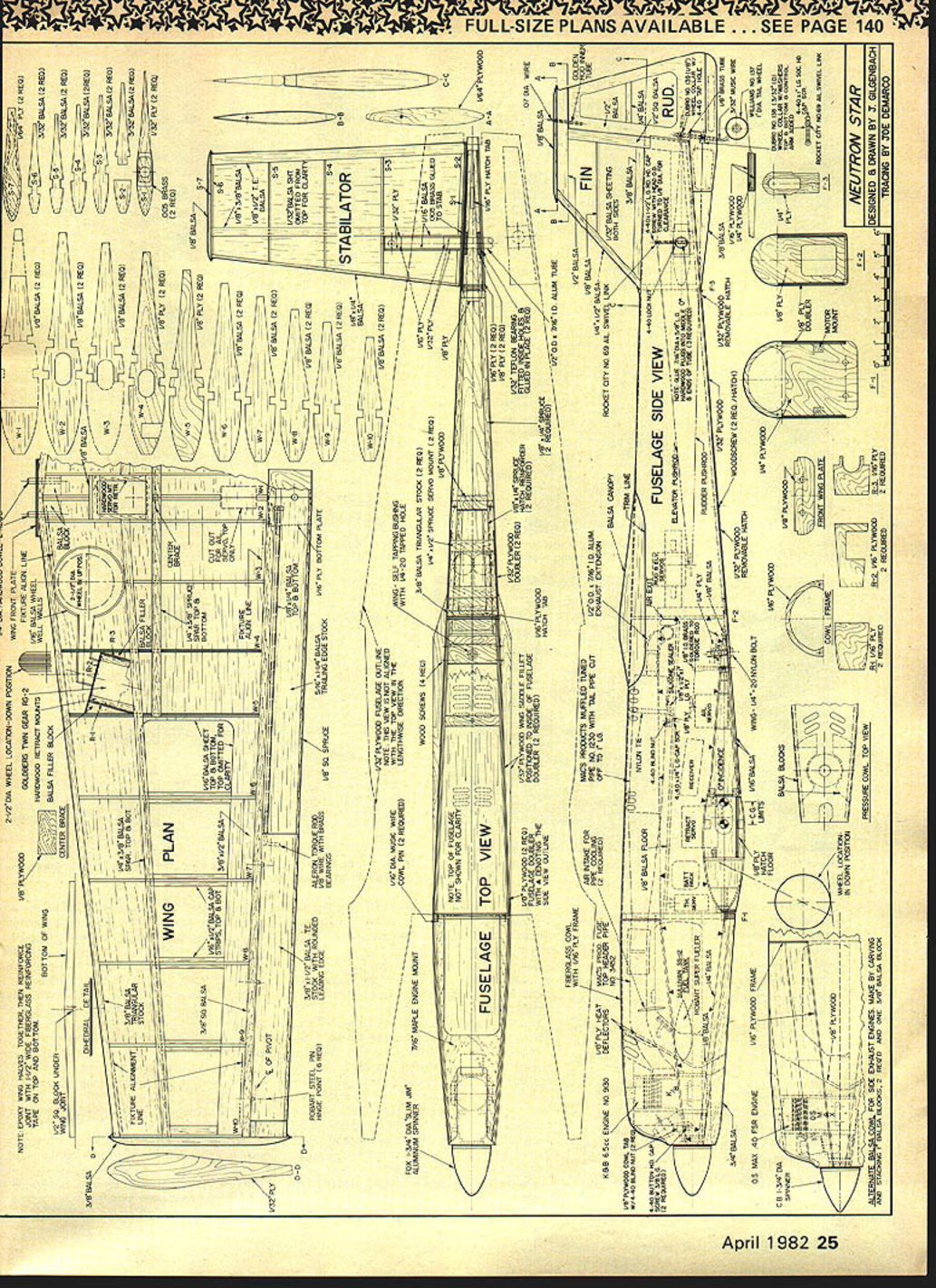
Neutron Star
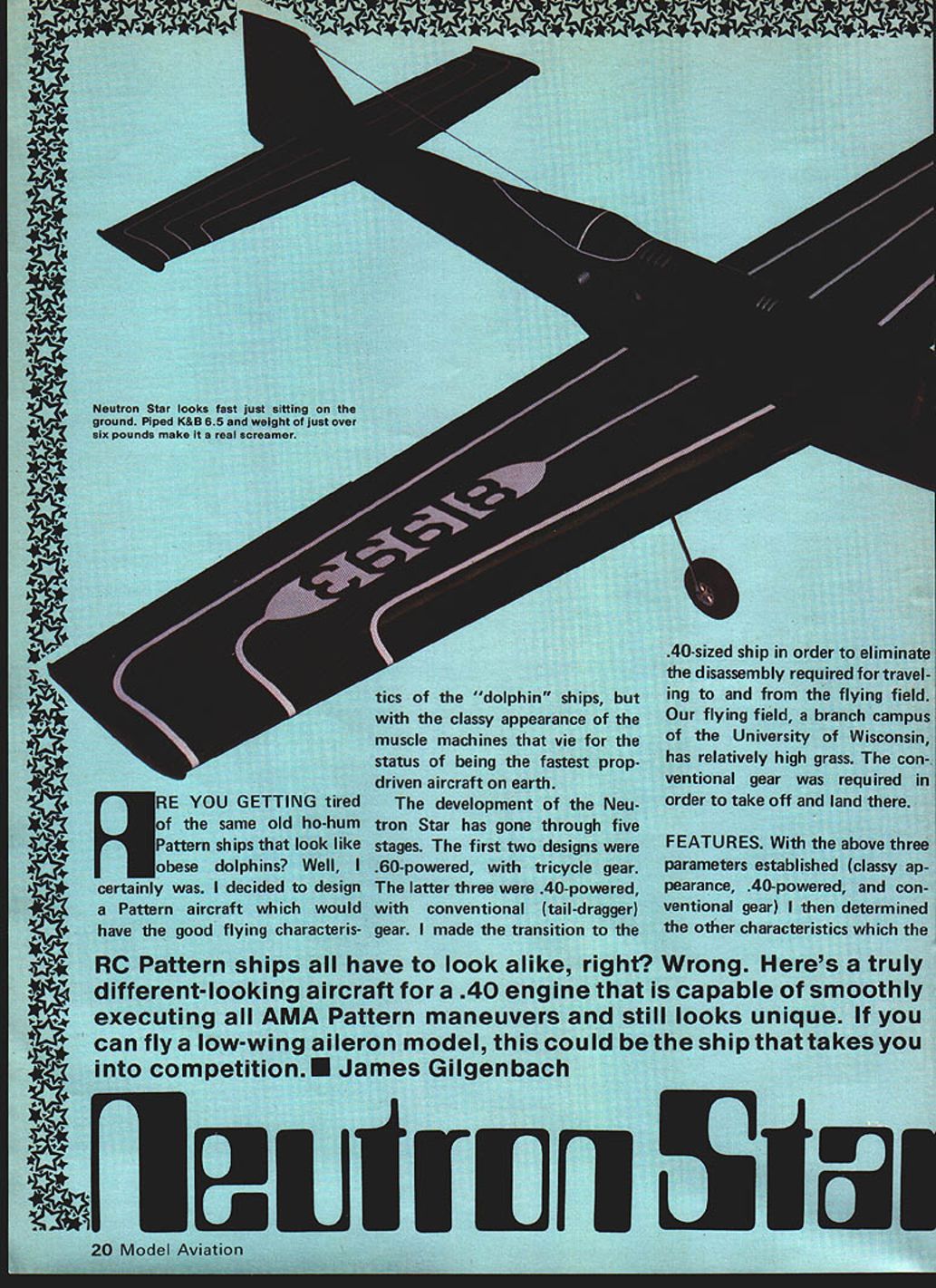
Are you getting tired of the same old ho-hum Pattern ships that look like obese dolphins? I was. I designed the Neutron Star to keep the good flying characteristics of those "dolphin" ships while giving a classier appearance—more like the muscle machines that vie for fastest prop-driven status.
Development
The Neutron Star development went through five stages. The first two designs were .60-powered with tricycle gear. The latter three were .40-powered with conventional (tail‑dragger) gear. The move to a .40-sized ship eliminated disassembly required for travel. Our flying field (a branch campus of the University of Wisconsin) has relatively high grass, so conventional gear was required for reliable takeoffs and landings.
Features
- Engine/exhaust: Side-exhaust engine chosen to eliminate an unsightly external tuned pipe and reduce drag. The exhaust exits out the side of the fuselage (rather than through the canopy) to resemble full-scale aircraft.
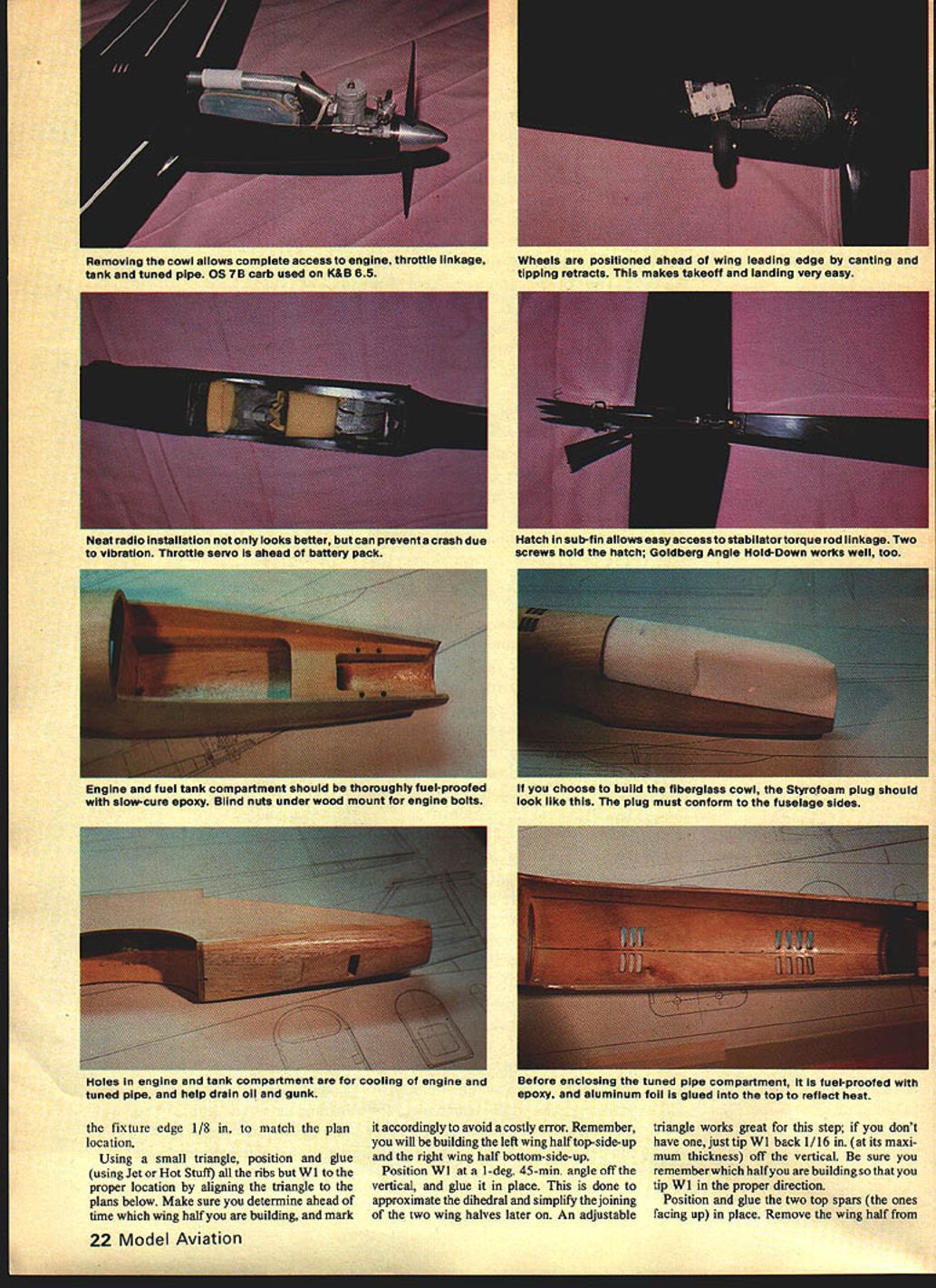
- Cowl: Fiberglass pressure-type cowl directs air past the engine to optimize cooling and has two air intakes to direct air through the tuned-pipe compartment. A simpler balsa cowl is provided as an alternative for side-exhaust engines. Either cowl is easy to make and gives good access—removing two screws exposes the engine and tank.
- Landing gear: Conventional gear is unique:
- Retracts are tipped and canted so main wheels are ahead of the wing leading edge when down, but behind the leading edge when retracted. This forward position reduces the tendency to nose over during takeoff and landing.
- Gear sets the aircraft at about a 6° angle of attack to ease takeoff and landing. Ground handling and taxiing are benign.
- Tailwheel allows rudder removal while providing a crash‑resistant assembly.
- Fixed gear can be used with only minor performance penalty.
- Wing and tips: Wing tip design smooths airflow over the tip, increasing tip-stall resistance and reducing drag. The same tip form is used on horizontal and vertical stabs for efficiency and appearance.
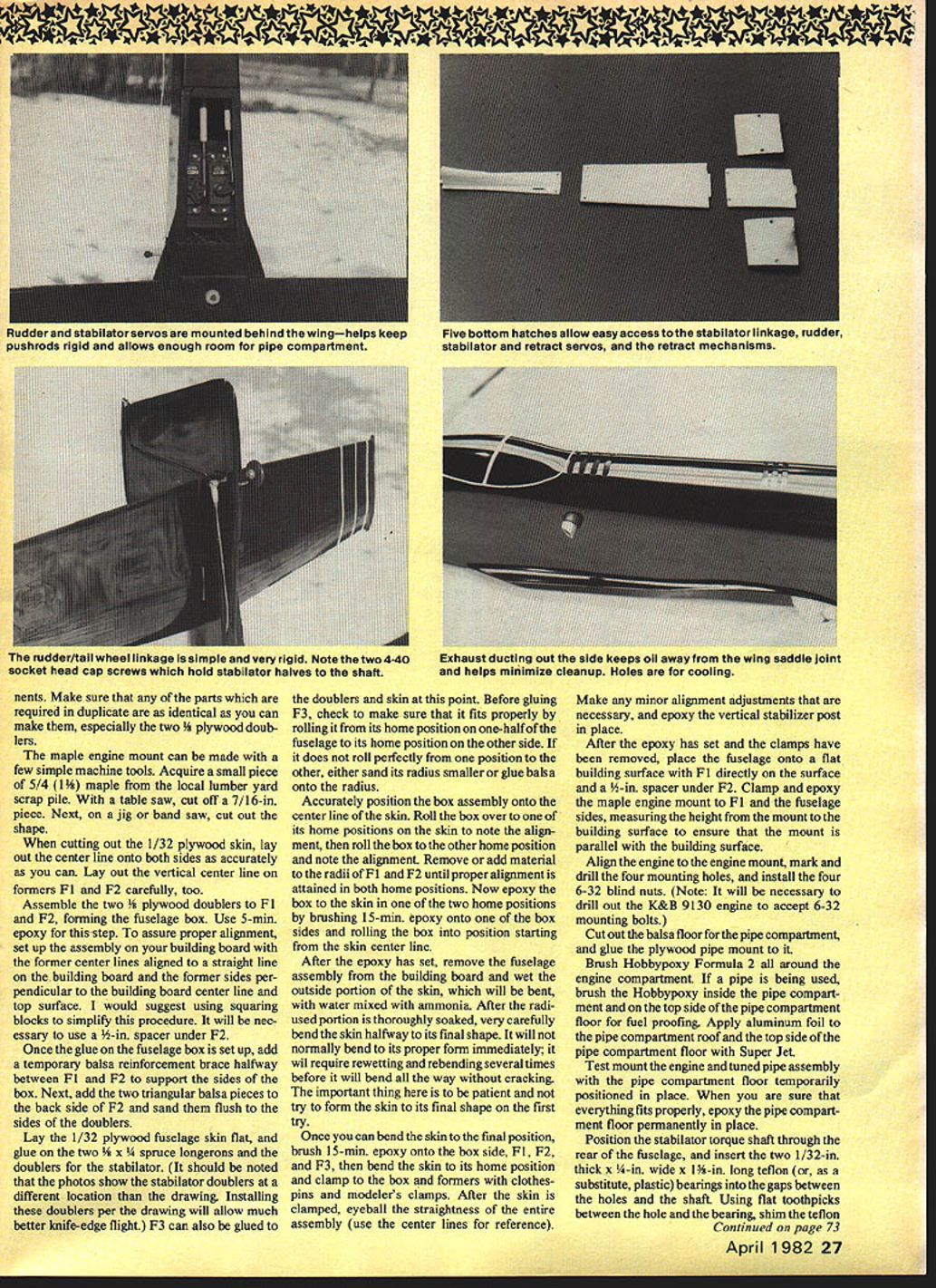
- Access: Five bottom hatches provide easy access to radio components and linkages.
- Simpler version: A simplified Neutron Star (fixed gear, side-exhaust engine, balsa cowl) can be built with about the same effort as a conventional sport plane.
WING CONSTRUCTION
Although you could core the wing from Styrofoam, the following steps describe building a straight, true built-up balsa wing.
- Preparation
- Cut out all wing components (except sheeting) and sand to size.
- If desired, order a second set of plans. Temporarily stick the plan to wood with 3M contact cement to trace ribs and parts; stick and remove the plan several times to weaken the bond so it can be removed later.
- Tape the wing plan to a flat building board and cover with waxed paper.
- Fixture blocks and layout
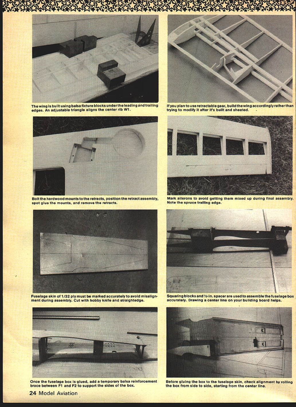
- Pin two 1" x 3" x 36" balsa fixture blocks (wrapped in waxed paper) onto the plan, aligning their edges to the outside of the fixture alignment lines. Ensure blocks are straight and the upper inner edges are sharp and uniform. Weight or pin them if necessary.
- Use 3/32" x 3/16" balsa scrap as spacer blocks at root and tip to set proper height.
- Leading/trailing edges and spars
- Pin the 3/8" triangular leading edge and 3/8" square trailing edge onto the fixture blocks, spaced back from the rib leading-edge line per the plan.
- Pin and glue the 1/8" x 3/8" spars and shear webbing. Add 1/32" plywood rib caps where indicated.
- Install dihedral braces and the center joiner plate. Make sure washout and dihedral are correct.
- Ribs and W1
- Using a small triangle, position and glue all ribs except W1 by aligning the triangle to the plans. Decide ahead which wing half you are building: left wing half builds top-side-up; right wing half bottom-side-up—mark halves to avoid error.
- Position W1 at 1°45' off vertical (tip it slightly back—about 1/16" at maximum thickness) to approximate the dihedral and simplify joining later. An adjustable triangle is helpful.
- Spars, shear webbing, and accessory pieces
- Position and glue the top spars (facing up) and the remaining spars. Add the 3/16" x 1/4" balsa piece between ribs W6 and W7 and the balsa block for the 1/4" diameter wing-locating dowel.
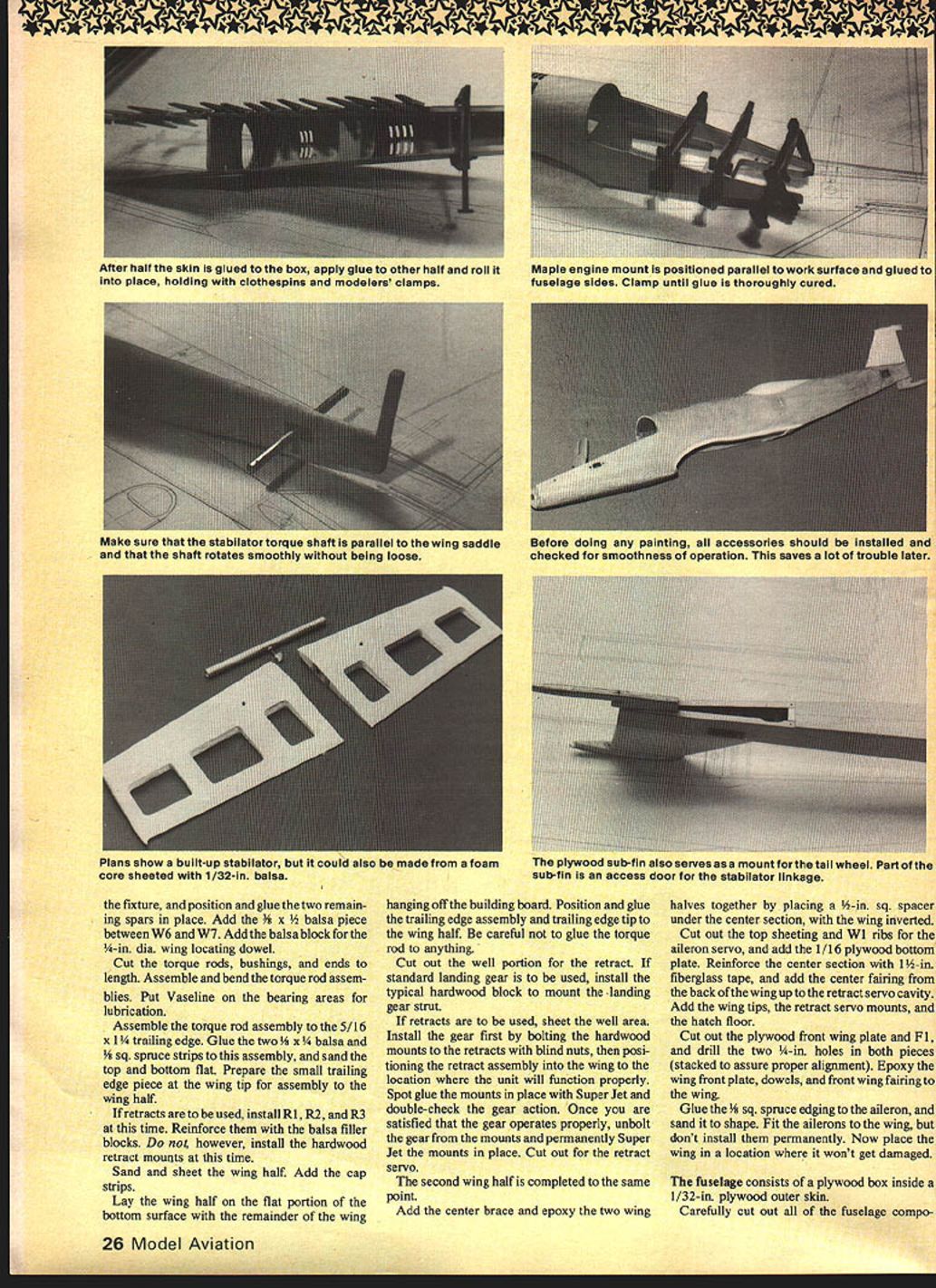
- Cut, assemble and bend torque rods, bushings and ends. Lubricate bearing areas with a little Vaseline. Assemble the torque rod assembly to the 5/16" x 1/4" trailing edge and glue the two 1/8" x 1/4" balsa and 1/8" sq. spruce strips to this assembly; sand top and bottom flat. Prepare the small trailing-edge tip piece.
- Sheeting and retracts
- Remove the wing half from the fixture and pin the bottom sheeting in place. Sheet with 1/16" balsa where shown. Complete sanding and fitting before joining halves.
- If retracts are planned, install ribs R1, R2 and R3 and reinforce with balsa filler blocks now (do not install hardwood retract mounts yet). Cut out the retract well portion; sheet the well area as needed. Bolt hardwood mounts to the retracts with blind nuts to test fit, position the retract assembly, spot-glue mounts with Super Jet and test action. Once satisfied, unbolt gear and permanently Super Jet the mounts in place, then cut out for retract servo.
- Finalizing wing half
- Sand, add cap strips, and prepare trailing-edge assembly. Lay the wing half on a flat portion of the building board with the rest hanging off, glue the trailing-edge assembly and trailing-edge tip, taking care not to glue the torque rod.
- Joining halves and center reinforcement
- Epoxy the two wing halves together. Place a 1/2" square spacer under the center section (wing inverted) while joining. Reinforce with 1/8" plywood as indicated on the plan.
- Cut top sheeting and W1 ribs for aileron servo access; add 1/16" plywood bottom plate. Reinforce center section with 1-1/2" fiberglass tape and add the center fairing to the retract servo cavity. Add wing tips, retract servo mounts and hatch floor.
- Front wing plate and ailerons
- Cut out the plywood front wing plate and F1, drill two 1/4" holes in both pieces stacked to assure alignment. Epoxy the wing front plate, dowels and front wing fairing to the wing.
- Glue 1/8" sq. spruce edging to the aileron and sand to shape. Fit ailerons but do not permanently install them yet.
- Notes
- If installing retractable gear, build the wing for retracts from the start—do not modify after sheeting.
- Bolt hardwood mounts to retracts prior to final installation. Mark ailerons to avoid mix-ups during final assembly.
FUSELAGE CONSTRUCTION
- Structure
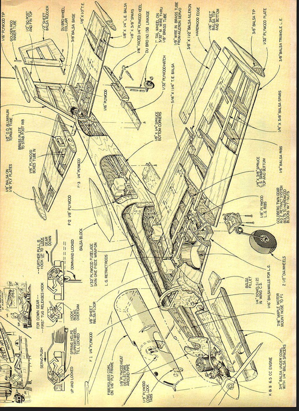
- The fuselage is a plywood box inside a 1/32" plywood outer skin, built over formers with 3/8" square stringers.
- Cut out all fuselage components from plywood and fit pieces on the plan. Glue firewall to bulkhead F2 and clamp to cure. Glue F1 to the firewall and attach side doublers to fuselage sides.
- Assemble fuselage sides to bottom and locate/glue formers F2, F3 and F4. Check top longerons alignment and glue top and bottom sheeting.
- Doublers, longerons and stabilator
- Lay 1/32" plywood fuselage skin flat and glue two 3/4" x 1/4" spruce longerons and stabilator doublers to it. (Note: install stabilator doublers per drawing for better knife-edge flight.)
- Fit F3 to doublers and skin and check rolling fit of F3 from one home position to the other; sand or add balsa to achieve smooth rolling radius.
- Gluing the box to the skin and bending
- Align the box assembly to the skin center line. Roll the box to one home position, note alignment; roll to the other and adjust F1/F2 radii until alignment is good.
- Epoxy one side of the box to the skin using 15‑minute epoxy, starting from the skin center line.
- After epoxy sets, wet the outside portion of the skin (the part to be bent) with water mixed with ammonia. Re-wet and rebend multiple times until the skin will bend to final form without cracking—be patient.
- Once bendable, brush on 15‑minute epoxy to the box side, F1, F2 and F3, bend the skin to home position and clamp with clothespins/modeler clamps. Check straightness against center lines and make final alignment adjustments. Epoxy the vertical stabilizer post in place.
- Engine mount and firewall
- After epoxy cures, place fuselage on a flat surface with F1 on the surface and a 1/8" spacer under F2. Clamp and epoxy the maple engine mount to F1 and fuselage sides, measuring height so mount is parallel to building surface.
- Align engine, mark and drill four mounting holes, and install four 6-32 blind nuts. (K&B 9130 engines must be drilled to accept 6-32 bolts.)
- Cut balsa floor for the tuned-pipe compartment and glue plywood pipe mount to it. Brush Hobbypoxy Formula 2 all around the engine compartment for fuel-proofing; if tuned pipe is used, brush Hobbypoxy inside the pipe compartment and on the top side of the pipe compartment floor. Apply aluminum foil to the pipe compartment roof and top side of the pipe compartment floor to reflect heat.
- Pipe and tank
- Test mount engine and tuned pipe with the pipe compartment floor temporarily positioned. When fit is confirmed, epoxy the pipe compartment floor permanently.
- Install engine cooling passages and fuel-proof both engine and tank compartments with Hobbypoxy Formula 2.
- Stabilator torque shaft and bearings
- Position stabilator torque shaft through the rear of the fuselage. Insert two 1/32" thick x 1/4" wide x 1-1/2" long Teflon (or plastic) bearings into the gaps between the holes and the shaft.
- Shim bearings in place with flat toothpicks between the hole and bearing, then epoxy. After epoxy cures, remove toothpicks, ensure bearings run snug to the shaft while keeping shaft parallel to the wing saddle.
- Super Jet the bearings to the fuselage, being careful not to glue the shaft to the bearings (a light coating of Vaseline on the shaft helps). Scrape bearing insides if necessary to allow free rotation without excessive play.
- Final assembly
- Install bottom of engine and tank compartments and remaining bottom fuselage panels, including sub-fin. Fit two access hatches and neat radio installation (throttle servo ahead; battery pack aft). A hatch sub-fin allows easy access to stabilator torque-rod linkage; two vibration-proof screws hold the hatch.
COWL AND CANOPY
- Fiberglass cowl: Made over a Styrofoam plug, faired to match fuselage sides, trimmed to fit and bolted on. The fiberglass pressure-type cowl directs cooling air and provides openings for tuned-pipe compartment ventilation and drainage.
- Balsa cowl: A simpler balsa cowl alternative is shown for side-exhaust engines.
- Canopy: Vacuum-formed plastic canopy fitted to fuselage.
- Access: Removing just two screws gives unobstructed access to engine and fuel tank.
BALANCE AND CONTROL THROWS
- Center of gravity: 3-1/2" back from the leading edge (check and adjust as required).
- Basic recommended throws:
- Ailerons: 3/8" up (high) / 3/16" down (low) — or 5/16" up and down for a moderate roll rate (three rolls in five seconds).
- Elevator (stabilator): 3/8".
- Rudder: 1".
- Trimming/competition throws:
- Stabilator (trailing edge): 7/16" up and 1/2" down for general flying. For snaps and spins increase to about 11/16" up and 13/16" down.
- Ailerons: 7/16" up and down for aggressive rolls/spins; dual rates recommended to switch between sport and competition throws.
- Rudder: ~1-1/4" left and right for consistent stall turns and spins; less for knife-edge and four-point rolls.
- Note: Use dual-rate feature to switch between gentle and aggressive throws. Adjust servo arms or centering screws to achieve these throws.
FINISHING
- Apply a good epoxy primer to fuselage, cowl, vertical stab, wing tips, stabilator tips, hatches and wheel wells; finish with desired paint (e.g., K&B Super Poxy). Cover wing, stabilator and rudder with Super Monokote or similar film.
- Color note: Black is often thought hard to see, but distant aircraft often appear as a black silhouette. A primarily black scheme with contrasting top colors helps distinguish top from bottom. Keep the aircraft shaded when not flying—black absorbs heat and can cause thermal trim changes.
TRIMMING AND FLYING
- Before first flight, recheck all controls for correct movement and smooth operation.
- The stabilator on this design is not overly sensitive—start with the recommended moderate throws and use dual rates for higher throw settings when needed.
- If built per plans, gross weight should be under about 6-1/2 lb with retracts and tuned pipe.
- The simplified version (fixed gear and standard muffler) can be built and flown by anyone experienced with a low-wing aileron model (e.g., Sig Kougar, Goldberg Skylark 56). The Neutron Star is resistant to wing-tip stalling and has no bad handling characteristics.
- With retracts, dual rates and a high-performance engine/muffled tuned pipe, the Neutron Star will perform all AMA Expert maneuvers with ease.
Bill of Materials
- Balsa:
- Four 1/32" x 3" x 36"
- Twelve 1/16" x 3" x 36"
- One 3/32" x 3" x 36"
- Four 1/8" x 3" x 36"
- One 1/4" x 3" x 36"
- One 3/8" x 3" x 36"
- Two 1/2" x 3" x 36"
- 3/16" x 3" x 36"
- Assorted 1/16", 1/8" and 1/4" strips for ribs, tips and gussets as shown on plans
- Aircraft plywood:
- One 1/64" x 3" x 6"
- One 1/32" x 12" x 48"
- One 1/16" x 6" x 12"
- One 1/8" x 12" x 24"
- One 1/4" x 6" x 12" (for keel and motor mount plates)
- Hardwoods:
- Two 1/8" x 3/8" x 36" spruce
- Two 1/4" x 3/8" x 36" spruce
- One 5/16" x 3/4" x 12" maple or other hardwood (dowel)
- One 1/8" diameter hardwood dowel (tailwheel support)
- Hardware:
- One pair Goldberg twin-gear RD-2
- One pair Du-Bro #250T wheels
- One Williams #137 wheel
- Two Du-Bro #140 wheel collars
- Four Du-Bro #138 wheel collars
- One Du-Bro #139 wheel collar
- Two Rocket City #69 aileron swivel links
- Four Du-Bro #136 6-32 blind nuts
- Thirteen Du-Bro #135 4-40 blind nuts
- Two 4-40 x 3/8" button-head cap screws
- One 4-40 x 1/4" button-head cap screw
- Two 4-40 x 1/2" socket-head cap screws
- Two 4-40 x 1" socket-head cap screws
- Two 4-40 x 1-1/2" round-head machine screws
- One 4-40 lock nut
- One 1/4" I.D. x 12" brass tubing
- One 3/32" I.D. x 12" brass tubing
- One 1/8" O.D. x 7/16" I.D. x 12" aluminum tubing
- One 1/16" x 36" music wire
- One 3/32" x 6" music wire
- One .070" x 1-1/2" pushrod wire
- Two 1/16" x 1-1/4" nylon clevises
- One 5/32" tapped hole
- One 1/4-20 nylon wing bolt
- Fourteen wood screws
- Six Robart steel pin hinge points
- One Sullivan SS-12 fuel tank
- One Robart Super Fueler
- Miscellaneous materials:
- One 1/4" Gold-n-Rod inner tubing
- One .005" x 1" x 4" fiberglass stock
- One 1/32" x 1" x 6" Teflon strip
- One 12" sq. 6-oz. fiberglass cloth
- One Ace 1/8" fiberglass reinforcing tape
End of instructions and materials.
Transcribed from original scans by AI. Minor OCR errors may remain.

