
A New Way to Make Super Fiberglass Fuselages
Revolutionary technique eliminates wood plug and female mold — foam is dissolved when shell is completed.
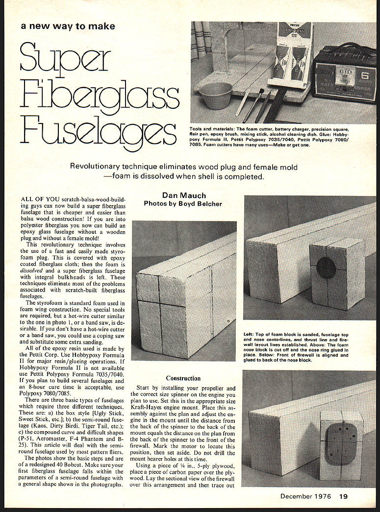
Dan Mauch Photos by Boyd Belcher
ALL OF YOU scratch-balsa-wood-building guys can now build a super fiberglass fuselage that is cheaper and easier than balsa wood construction! If you are into polyester fiberglass you now can build an epoxy glass fuselage without a wooden plug and without a female mold!
This revolutionary technique involves the use of a fast and easily made styrofoam plug. This is covered with epoxy-coated fiberglass cloth; then the foam is dissolved and a super fiberglass fuselage with integral bulkheads is left. These techniques eliminate most of the problems associated with scratch-built fiberglass fuselages.
The styrofoam is standard foam used in foam wing construction. No special tools are required, but a hot-wire cutter similar to the one in photo 1, or a band saw, is desirable. If you don't have a hot-wire cutter or a band saw, you could use a coping saw and substitute some extra sanding.
All of the epoxy resin used is made by the Pettit Corp. Use Hobbypoxy Formula II for major resin/gluing operations. If Hobbypoxy Formula II is not available use Pettit Polypoxy Formula 7035/7040. If you plan to build several fuselages and an 8-hour cure time is acceptable, use Polypoxy 7080/7085.
There are three basic types of fuselages which require three different techniques. These are: a) the box style (Ugly Stick, Sweet Stick, etc.); b) the semi-round fuselage (Kaos, Dirty Bird, Tiger Tail, etc.); c) the compound curve and difficult shapes (P-51, Aeromaster, F-4 Phantom and B-25). This article will deal with the semi-round fuselage used by most pattern fliers.
The photos show the basic steps and are of a redesigned 40 Bobcat. Make sure your first fiberglass fuselage falls within the parameters of a semi-round fuselage with a general shape shown in the photographs.
Construction
Start by installing your propeller and the correct size spinner on the engine you plan to use. Set this in the appropriate size Kraft-Hayes engine mount. Place this assembly against the plan and adjust the engine in the mount until the distance from the back of the spinner to the back of the mount equals the distance on the plan from the back of the spinner to the front of the firewall. Mark the motor to locate this position, then set aside. Do not drill the mount bearer holes at this time.
Using a piece of 1/4 in., 5-ply plywood, place a piece of carbon paper over the plywood. Lay the sectional view of the firewall over this arrangement and then trace out the vertical and horizontal thrust lines and lay out the holes for the motor mount, fuel lines, throttle linkage and steering linkage. Center the motor mount on the front firewall, align the thrust lines and mark the holes. Now drill the holes for the motor mount, fuel lines, throttle linkage and steering linkage. Sand the outside edges until you have duplicated the taper shown on the plans; place aside.
Using a piece of 1/16 in. plywood, make the nose ring identical to that shown on the plans, except cut out the center hole. Be sure to sand the taper on the periphery of the nose ring as shown on the plans. Place the completed nose ring and firewall against the plan to assure the parts are accurate.
Lay a large piece of poster board on a drafting table. Lay long sheets of graphite (carbon) paper over the poster board. Lay the plans over the arrangement; the poster board must be long enough to trace the entire side and top view, therefore it will be necessary to make templates in sections. Make the templates from the outside lines of the side view, including the nose ring, back end, wing saddle and tail. Be sure to draw the stabilizer cut-out. Repeat the procedure for the top view, making sure to trace the centerlines from nose to tail onto the templates. When the lines are transferred to the poster board, carefully cut out the shapes and cut out the stabilizer lines at this time. Check the templates against the plans and set the templates aside.
Sheet 4-in. foam: cut out a block the same length as the templates. Make the blocks wider and deeper than the templates. If you cannot obtain 4-in. thick foam, you can laminate two pieces of 2-in. foam to form one 4-in.-wide block. Regardless of whether you use 2- or 4-in. foam, you must make sure that the top is straight, that the top is cut 90 degrees to the sides and the front is cut 90 degrees to the sides and top, unless thrust offset is required. The top or sides can be sanded straight by contact cementing a piece of 69-grit open-coat sandpaper to a flat board. Plane the block of foam over the sandpaper until the block of foam is straight along the top and 90 degrees to the sides.
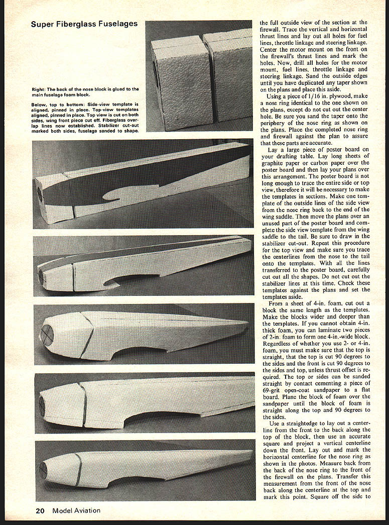
Use a straightedge to lay out a centerline from the front to the back along the top of the block, then use an accurate square and project a vertical centerline down the front. Lay out and mark the horizontal centerline for the nose ring as shown in the photos. Measure back from the back of the nose ring to the front of the firewall on the plans. Transfer this measurement from the front of the nose back along the centerline at the top and mark this point. Square off the side to the full outside view of the section at the firewall. Trace the vertical and horizontal thrust lines and lay out all holes for fuel lines, throttle linkage and steering linkage. Center the motor mount on the front on the firewall's thrust lines and mark the holes. Now, drill all holes for the motor mount, fuel lines, throttle linkage and steering linkage. Sand the outside edges until you have duplicated any taper shown on the plans and place this aside. Cut off the wing fairing block at this point and lay out and then draw a line across the top from side to side. Using the square, project this line from the top down each side. Pin 1/8 x 1/2 in. spruce strips against the side lines just drawn, and cut off the nose block using a hot-wire cutter (bow-type), or saw it off using a band saw. Make sure you cut it straight.
Project the top centerline down the back of the just cut off nose block. Lay out and draw the horizontal thrust line onto the back of the nose block. Using Hobbypoxy Formula 4, glue the back of the nose ring to the front of the foam block lining up the centerlines of the nose ring. Use the glue sparingly and keep the glue 1/8 in. away from the outer edges. When this cures glue the front of the ply firewall to the back of the nose block as shown in the photographs. When cured glue the back of the firewall to the large foam block using straightedges to keep the assembly aligned while it cures.
Foam Cutting
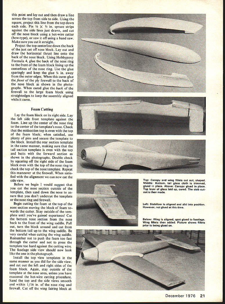
Lay the foam block on its right side. Lay the left side front template against the foam. Line up the center of the nose ring to the center of the template's nose. Check that the midsection top is even with the top of the foam block; when satisfied, use plenty of pins and secure the template to the block. Install the rear section template in the same manner, making sure that the tail section template is even with the top and butts with the forward section as shown in the photographs. Double check by squaring off the right side of the foam block even with the top of the nose ring to check the top of the nose template. Repeat this maneuver at the firewall. When satisfied with the alignment we can now cut the side view.
Before we begin I would suggest that you cut the nose section outside of the template, then sand down the nose to assure that you don't undercut the template or the nose ring and firewall.
Begin cutting the foam at the top of the nose section moving the block of foam towards the cutter. Stay outside of the template until you've gained experience! Cut the bottom nose section from the nose back to the front of the wing saddle. Pull out, turn the block around and cut from the bottom tail up to the wing saddle. Be very careful when cutting the wing saddle. Remember not to push the foam too fast through the cutter and not to press the template too hard against the cutting wire.
The fuselage side view should now look like the one in the photograph.
Install the top view templates in the same manner as you did for the side view, and cut out the left and right sides of the foam block. Again, stay outside of the template at the nose area, unless you have mastered the hot-wire cutting procedure. Sand the top and the side views smooth and within 1/16 in. of the nose ring and firewall. Cut off the wing fairing block at this point and lay out and then draw a line across the top from side to side. Using the square, project this line from the top down each side. Pin 1/8 x 1/2 in. spruce strips against the side lines just drawn, and cut off the nose block using a hot-wire cutter (bow-type), or saw it off using a band saw. Make sure you cut it straight.
Project the top centerline down the back of the just cut off nose block. Lay out and draw the horizontal thrust line onto the back of the nose block. Using Hobbypoxy Formula 4, glue the back of the nose ring to the front of the foam block lining up the centerlines of the nose ring. Use the glue sparingly and keep the glue 1/8 in. away from the outer edges. When this cures glue the front of the ply firewall to the back of the nose block as shown in the photographs. When cured glue the back of the firewall to the large foam block using straightedges to keep the assembly aligned while it cures. the leading edge of the wing saddle. (See photos for details.)
Draw lines from the center of the wing saddle leading edge forward to a point 1/4 in. above the bottom of the nose ring on both sides of the foam core. Draw a line from the top back of the wing saddle to a point 1/2 in. above the bottom at the tail. Do this on both sides of the foam plug. These lines are for the fiberglass overlap reference line.
Take the side view template and cut out the area for the stabilizer. Pin the template to the side of the core and lay out the stabilizer cutout. Make sure these lines are dark to show through the fiberglass which will be described later on.
Sanding
All sanding is accomplished with 60-100 grit aluminum oxide open-coat sandpaper. Use a sanding block to keep the areas straight and sand in one direction only.
Now study the sectional views and your foam core. Begin sanding a wide bevel from the left corner of the nose ring back to the firewall. Sand about ten passes on the left hand side and ten passes on the right side. This is important to keep the plug symmetrical during sanding. When you have sanded the nose section to within 1/16 in. of the nose ring, start sanding the radius for the left and right sectional views. Start taking longer strokes to sand back to the end of the top of the wing section. Keep moving from the left to the right sides keeping everything even. As you near the very end of the tail be very careful not to over-sand. Continue sanding the curve in the top and sides until you have duplicated the sectional views. In the same manner sand the bottom nose section and bottom tail section.
Re-establish the fiberglass overlap reference lines and the top centerline. Now check the entire shape to assure that it is within the shape shown on the plans. Fill any deep dents, gouges or pits with Dap spackling compound. Fill any low spots around the nose ring or firewall in the same manner but keep the compound off of the wooden parts. Sand smooth when hard.
Cut out top and side view templates for the wing fillets and the canopy. While a fiberglass canopy can be omitted, do not omit the wing fillets because they give the structure substantial rigidity. A clear plastic canopy can be installed after all fiberglassing has been completed but a built-in glass canopy is popular today and also lends additional strength to the fuselage. Cut out the foam canopy and wing fillets using your templates as a guide. Sand the canopy to shape, then fit the bottom of the canopy to the fuselage. Once the canopy has been fitted glue it to the fuselage using Hobbypoxy Formula 4.
Rough sand the wing fillets to the shape Use a 1/4 in. dowel wrapped with sandpaper to make the radius at the leading edge of the fillets; use larger shapes to bring the radius all the way to the end of the fillets. Use light pressure while sanding and keep your fingers behind the area being sanded to keep the foam from breaking. Final sanding of the fillets takes place after the basic fuselage has been fiberglassed. Set the wing fillets aside for now and we'll begin fiberglassing.
Fiberglassing
Fiberglassing is probably the most difficult but important task involved in this procedure. The following paragraph covers certain facts that have been tried and should be observed while performing the fiberglassing operation:
- Do not attempt to cover the entire fuselage with one piece of glass. You will develop several wrinkles and, while you may get the top and sides looking good, you'll have large air pockets or wrinkles on the bottom. This is due to gravity.
- Do not apply excessive heat to speed the curing. I have found that 90 to 95 degrees F. is a good curing temperature.
- Be careful not to deform or warp the parts of the fuselage when wet and working out the air pockets. Check for this condition after you have finished laying up the glass cloth but before the epoxy sets. A slight readjustment of the glass cloth will correct this condition; however, it can be prevented by having adequate support at the nose, midsection, and tail.
Now let's start glassing. Dust off all loose foam particles and set the fuselage in a support stand similar to the one in the photographs. Cut out a piece of 10-oz. tight-weave fiberglass cloth to cover the entire bottom of the tail section from the wing saddle to the tail. Trim the glass cloth with a sharp pair of scissors or an X-acto knife. Trim the cloth so that, when the cloth is laid on the bottom of the fuselage, it will extend down to the fiberglass overlap reference line. You should be able to see this line through the glass cloth. Now mark the trim line on the glass cloth for both sides of the bottom tail section. Cut this piece to the lines drawn, making sure that you get a clean cut and you don't warp the line by pulling the weave at an angle to the fiber orientation.
Using the above instructions, cut another piece of 10-oz. glass cloth for the bottom nose section. Now remove all loose fibers and lay these pieces of cloth in their respective locations. Work the glass until it conforms by smoothing it out carefully. Now lift the pieces off gently so that they retain their shape. Mix two tablespoons of Hobbypoxy Formula II to one tablespoon of hardener. Stir with a stiff epoxy brush and wet the glass cloth, making sure the cloth is thoroughly wetted out. Start working in the glass cloth from the center and move toward the edges, pressing out any trapped air with the brush. This is the first coat (the wet coat) and will only be tacky to the touch. Do not panic if you get wrinkles. They can be smoothed out in the second coat.
Once the first coat has been applied to the bottom of the tail and nose sections, lay the fuselage aside and allow the epoxy to tack off slightly. Next, cut two side pieces for the tail section from 10-oz. cloth. Fit them to the sides and wet them out with the same mixed epoxy. Apply the cloth in the same manner, working from the center to the edges. Use newspaper or waxed paper under the area to protect the support stand. After the cloth is in place, apply a second coat of epoxy, wetting out the glass again and smoothing out any wrinkles.
When this has been completed, allow the bottom and side sections to cure thoroughly. Sand any high spots smooth and remove any runs. Cut out the top piece of 10-oz. cloth to cover the entire top of the fuselage from nose ring to tail. Wet it out and apply it in the same manner. When all pieces are applied, let the assembly cure thoroughly.
After curing, sand the outside gently with 220-grit paper and apply a filler coat of epoxy resin mixed with milled glass or talc to fill the weave. Sand smooth when cured. Final shaping of the fuselage can now be accomplished with a sanding block and 220-grit paper. After final sanding, wipe the fuselage down with denatured alcohol and apply a primer/sanding sealer. Sand smooth and paint. Brush, brush on a thin layer of resin to the tail surface at the bottom. Work quickly but neatly. Extend the glue down to the overlap reference line. Now lay the glass cloth over the tail section, work out the wrinkles and make sure that the cloth lines up with the reference lines, do not brush additional epoxy resin on to the glass except at the reference line.
After you are satisfied that the cloth has been glued down to the foam, is smooth, and has not warped the tail section, let it set. The purpose of the 15-min. epoxy is only to glue this piece in its proper position. Hobbypoxy Formula II or Pettit 7035/7040 epoxy glue can be used and is the preferred method; but you would have to wait four hours after application before you can continue with the next step. For the sake of expedience, 15-min. glue is used to fasten the bottom nose section and bottom tail section glass cloth in place. While the glue is curing on the tail section, glue in place the piece of glass cloth that you cut for the bottom nose section, using Hobbypoxy Formula II. When the glue has set on the bottom nose section trim any excess glue, runs, or loose fibers that extend below the reference line and cut away the excess over the nose ring. Do not try to fold the glass cloth over the nose ring as you will probably develop an air pocket. Also trim the excess cloth in the wing saddle. Check the bottom tail section and trim off any excess glue or cloth.
Now sand the epoxy glue at the fiberglass overlap reference line on both sides, front and back. Sand the glue, but do not sand into the cloth. Additionally, you only want to sand no further than 1/4 in. above the reference line with the fuselage upside down as shown in the photograph. If you are building a .40-powered fuselage, cut a piece of 10-oz. glass cloth to cover the entire top from the nose to tail and down the sides at least one inch beyond the reference line. If you cannot pick up the reference line through the glass cloth, remove the top layer of the cloth and re-mark the reference line with a fair tip pen.
If you are building a .60-size fuselage cut one piece of 7-oz. glass cloth to cover the entire top and sides. Cut a half piece of 7-oz. glass cloth to cover from the nose back 2 inches beyond the wing saddle. For either a .40- or a .60-size lay the full piece of glass cloth over the fuselage and smooth it out. Work the cloth from the nose to the tail, then from the nose down the sides and in then towards the tail. The sole purpose of this step is to ascertain where, if any, wrinkles tend to appear. If your fuselage will not have a fiberglass canopy there should be almost no tending to have a wrinkle; on the other hand, a built-in canopy will probably tend to have a wrinkle show up at the top near the nose and in the wing saddle area. Depending on your particular canopy design you will probably be able to eliminate the one in the nose section by working the cloth from the middle of the canopy along the top and down towards the front. There should be no problem with wrinkles in the mid section since it will be covered with the wing fillets. If one is persistent in the nose area, work it to the area where the engine cut-out will be made and eliminated when this is cut out.
The dry run described is the same as the technique used with epoxy and will be valuable experience in working the cloth and observing any tendencies to form folds or wrinkles. All wrinkles will be slit and overlapped at the point the fold occurs. Remove the glass cloth from the fuselage and set aside. Remove any loose glass fibers from the styrofoam plug.
Now that we are all experts, we can proceed with the actual glassing operation. Mix three tablespoons of Hobbypoxy II glue to three tablespoons of hardener. Mix thoroughly, keeping in mind the temperature factors for the working life of the material. Give yourself all the time available for this step (35 minutes). Brush on a coat of resin over the center top and sides of the fuselage. Extend the layer of resin at least 1/8 in. below the fiberglass overlap reference lines. This coat of resin should be a liberal coat but should not be a heavy coat. Check to make sure the foam plug is adequately supported at the nose, midsection, and tail.
Next lay the glass cloth over the entire fuselage, top and sides. Even up the cloth between the sides, the nose and the tail. Work the cloth from the nose up the top and over the canopy and back over the top and sides of the tail. Return to the nose and rework the cloth from the top of the nose to the front of the canopy then down the sides back towards the nose. Continue working the cloth up over the canopy, holding the cloth at the front and top of the canopy with a wooden mixing stick (Popsicle stick). With another mixing stick work the cloth over the top to the back of the canopy. Now move the mixing stick that was at the front of the canopy and lay it on edge at the top middle of the canopy. With the free hand use the other mixing stick and squeeze the cloth down the left side of the canopy. With the same mixing stick now work the glass cloth down the right side of the canopy.
When you reach the junction of the bottom of the canopy and the fuselage top, hold the mixing stick at this junction. Remove the mixing stick from the top of the canopy and work the cloth down the side to the wing saddle. Return to the left side of the canopy and hold the glass cloth at the junction of the fuselage and the canopy; then work the cloth down the right side with the mixing stick. Set the sticks in denatured alcohol and continue working the cloth to the tail and down the side with an epoxy brush toward the tail, then down the side until you reach the end of the tail.
Repeat the above procedure to assure that the glass cloth is in full contact with the foam and that the epoxy glue has gone through the glass cloth and the excess resin has been carried away. Set aside and let it cure for 8 hours. While the fuselage is curing, build the stabilizer, elevator, fin and rudder. You can work on the wing to round out your evenings. After the glue has cured on the top and sides, drill a small hole in the ply nose ring at the center. Press a nail into the nose ring and push a piece of 1/16" x 6" rod straight into the base of the tail. The nail and rod are used to support the fuselage after you brush a second coat of epoxy over the entire fuselage. Keep this coat light enough so it doesn't run. Let the second coat cure overnight while it is supported.
When this coat is cured, scrub the entire fuselage with a stiff bristle scrubbing brush and Bon Ami cleanser. Rinse thoroughly and blow dry with a hair dryer. Sand any glue runs. Trim the excess cloth below the fiberglass reference lines. You should maintain a 1/8 to 3/8 in. overlap. Again, avoid sanding into the glass cloth except at the overlap lines.
If you are building a .60-size airplane lay up the half layer of 7-oz. glass cloth in the same manner as described above. Be sure the cloth extends from the nose to a few inches beyond the back of the wing saddle and down the sides to 1/2 in. below the reference line. Sand when cured. Lay up another piece of glass cloth over the bottom nose section and overlap at the sides at the reference line. When this is cured put on a coat of epoxy resin and let cure overnight.
Now inspect the fuselage to make sure the fiberglass is completely filled. There will probably be some areas that will have a waffle appearance. This should be eliminated by spot touch-up with epoxy resin.
Cut the slot in the fuselage for the stabilizer. Finish the stabilizer with epoxy resin. Sand smooth when cured. Join the elevator and stabilizer using conventional techniques. With the elevator and stabilizer completed, slide the stabilizer into the cut-out and check the alignment. When the stabilizer is aligned, glue it in place with Hobbypoxy Formula 4. When glue is set, turn the fuselage upside down and set the wing in place. Sand the wing saddle area until the wing is at the proper incidence. Spot glue the wing to the fuselage where the aileron servo cut out will be made.
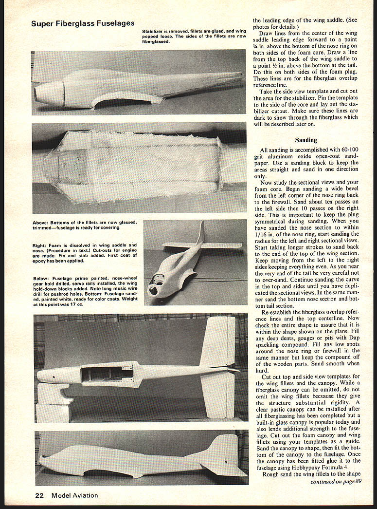
Turn the wing over and with a light coat of Hobbypoxy 4, glue both wing fillets in place. Make sure there is full contact with the wing and fuselage. When the glue is cured, sand the wing fillets to the final shape. Pop the wing loose from the wing saddle. Cut two pieces of glass cloth for the wing fillet sides. Cut two pieces of glass cloth for the bottoms of the wing fillets. These pieces can be laid up using 5-minute epoxy to position them. After the 5-minute glue has set, trim the excess glass cloth, apply a coat of Hobbypoxy II to the glass cloth and set aside while it cures.
Hold the fuselage up to a light and sight along all surfaces. Observe any areas that show shiny spots. These are low spots, which if not corrected will cause the surface to be wavy. To correct any waviness brush on a third coat of resin over the entire fuselage. Let this cure overnight and then sand with 100-grit open-coat sandpaper to remove the glaze. Switch to 240-grit wet-or-dry and wet sand using isopropyl alcohol. You should now have a satin smooth fuselage ready for a final wet sand with 400-grit wet-or-dry paper.
Foam Removal
In this step we will remove only the unwanted foam in the nose section and midsection. Do not remove the foam in the tail section as this adds little weight but gives additional strength. If the wing fillets are completely sealed, the foam will not be dissolved in the fillets.
Start by laying out the hole to be cut in the nose ring. Cut a hole through the nose ring into the foam with a Dremel moto-tool. Lay out the nose section for the engine cut. Cut along the line with a hot-knife attachment on your soldering iron. Do not try to pull this piece off. It will fall off in a later step. Decide if you want an access panel cut in the bottom of the fuel tank compartment. If you do, lay out the shape and cut with a hot knife. Again do not try to pull this panel off. It will fall off in the next steps.
Obtain a pint of gasoline and take the fuselage outdoors. No smoking. Stay away from any possible sparks, etc. Now point the nose down into a large can at a 75-degree angle to the horizon with the bottom of the wing saddle facing you. Pour a little gasoline into the middle of the wing saddle. In a few seconds the foam will start to dissolve. Pour another ounce of gas into the wing saddle in the same place. At no time should you pour it in at the back of the wing saddle or tilt the nose up. Pour another ounce of fuel into the wing saddle with the fuselage vertical. The tank compartment panel should have fallen off by now and almost all the foam would be dissolved in the wing saddle and tank compartment. The nose section should be partially dissolved with the gasoline that flowed through the holes in the firewall. Remove the engine cut-out panel and pour a little more gas into the nose section. Now all the foam should be dissolved and all that remains is dissolved foam. Rinse out the entire inside of the fuselage for two full minutes with cold water, then pour hot water into the fuselage and remove the remains of the foam. Remove all that can be reached. Shake all the loose water out and dry inside and out with an old cloth. Leave it outdoors overnight to eliminate the strong odor. Scrape the inside of the fuselage to remove any hardened pieces of foam residue. Remove the remaining foam at the back of the wing saddle with a Dremel and drum sander.
Finishing the Fuselage
Temporarily install the motor mount to the firewall. Set the engine in place. Install the propeller and spinner. With everything in line, mark the holes for the engine bearers. Remove the engine and motor mount and drill the holes. Reinstall the motor mount. Reinforce the back of the firewall with a piece of fiberglass tape, using Hobbypoxy Formula 4.
Make a bulkhead for the front of the wing saddle to mount the wing, using dowels or a block of hardwood to bolt the front of the wing in place. Fit this piece so that there is no bulging or recession in the fuselage. Glue in place with 5-minute epoxy. Make two servo tray mounting rails. Carefully fit these pieces and glue in place.
Cut a slot in the top of the tail for the vertical fin or place according to the plans. Install the rudder and elevator horns. Posi- tion your servos in the servo tray and set them on the rail. Check the direction of the servos for proper orientation to give the correct side of the servo output arm so the controls will be correct. Use a piece of straight 3/16 x 24" landing gear wire and position this over the bottom of the fuselage from the elevator servo to the elevator horn. Mark this line with a pencil. Draw another line on the side of the fuselage from the horn to the servo to establish the location and angle of the pushrod exit. Repeat this step for the rudder servo. Cut out the servo pushrod exits with a hot knife and remove the panels. Sharpen one end of the 3/16 inch landing gear wire to a point. Grind a flat onto the point to form a router bit. Start the router into the exit, keeping it in line to make the lines on the bottom and side of the fuselage. When the router bit gets too hot or is hard to turn by hand, chuck up the end in an electric drill. Hold the fuselage securely and drill up to the servo. Remove the router and drill the other exit in the same manner. Install the Nyrods and clevises. Now try to deflect the control surface. You will find that the Nyrods are just as stiff as wooden pushrods.
Install the wing hold-down blocks and glue them in place. Align the wing and drill for the hold-down bolts. Remove the servos and anything you don't want painted. Prime the entire fuselage with Hobbypoxy undercoat. Sand it almost all off when it dries with 400 wet-or-dry sandpaper. Now paint the fuselage with your favorite Hobbypoxy colors. With all the painting completed, install the fuel tank, cowl, engine, radio equipment, linkage and landing gear. Check for proper operation and directions.
I will be glad to answer any questions addressed to me in care of this magazine.
Transcribed from original scans by AI. Minor OCR errors may remain.

