
NIBBLE 300
Norman D. Poti
1/2A gas has traditionally been one of the most popular Free Flight events, for a variety of reasons including simplicity, low cost, and small size. Some of the same attributes apply to the generation of, and recent surge in, the F1J Power event. Miniaturization of Schnuerle-port engine technology into .061s and .049s has breathed new life into the small gas events heretofore dominated by Cox Tee Dees.
(Editor's note: F1J is an FAI event—the "international" 1/2A class—for models powered by engines with displacements of .061 cubic inches (1 cc) or less. AMA 1/2A Gas limits displacement to .050 cubic inches.)
Nibble 300 was created to fill a void in Poti's hangar: a small, reliable, fun model that could perform a dual role in 1/2A Gas and F1J Power. The process from conception to first flight spanned three years.
The dual role of Nibble 300 revolves around the CS .049 engine. A powerful Doug Galbreath–modified CS was procured (note: Galbreath no longer offers engines). Research into the experience base with this power plant resulted in the selection of a 300-square-inch wing.
Progress was sidelined for other priorities, but interest was rekindled the next winter. Comparison of aspect ratios and tail volume coefficients for the author's successful B and C Gas Niblites led to the final planform layout. Acquisition of a fuselage system from Ken Oliver (2213 El Cejo Dr., Rancho Cordova, CA 95670) and construction of the flying surfaces was accomplished the second year, before another hiatus put the project on hold again. The concept was finally brought to fruition in 1995 with completion of the model and first flights.
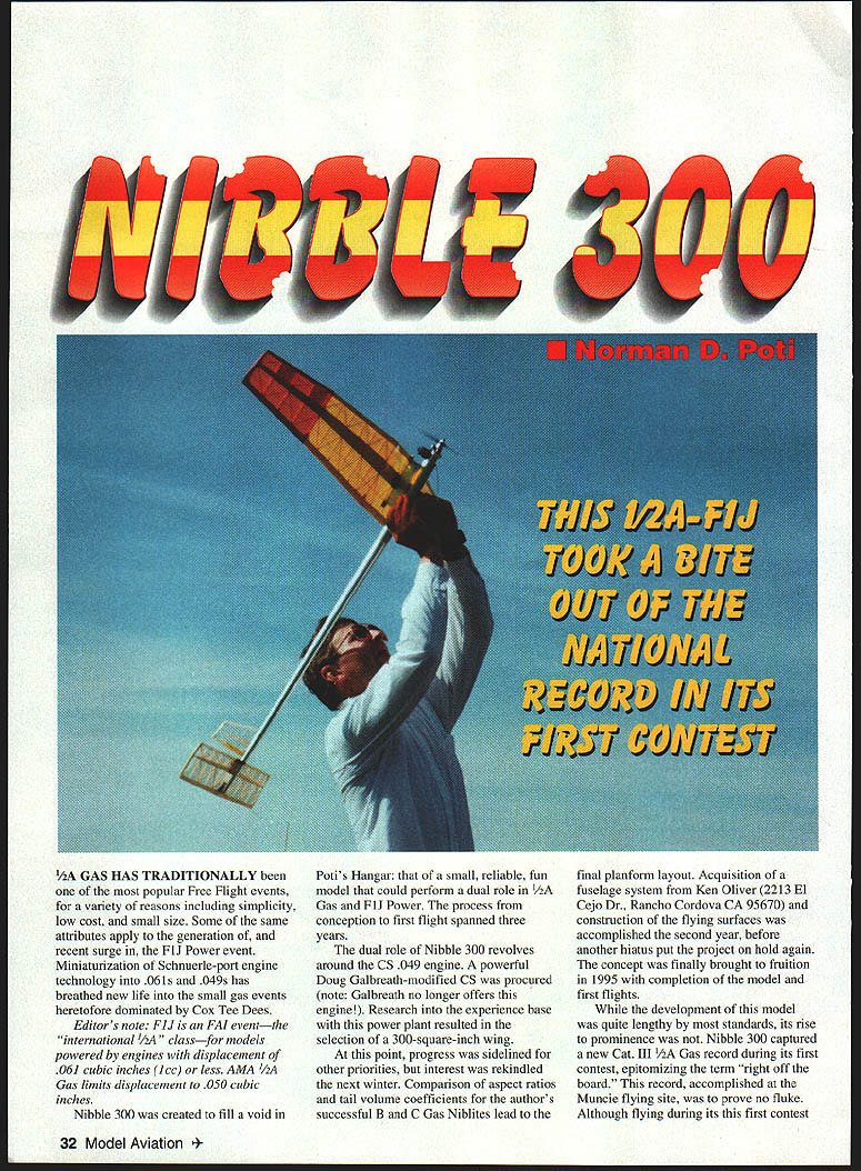
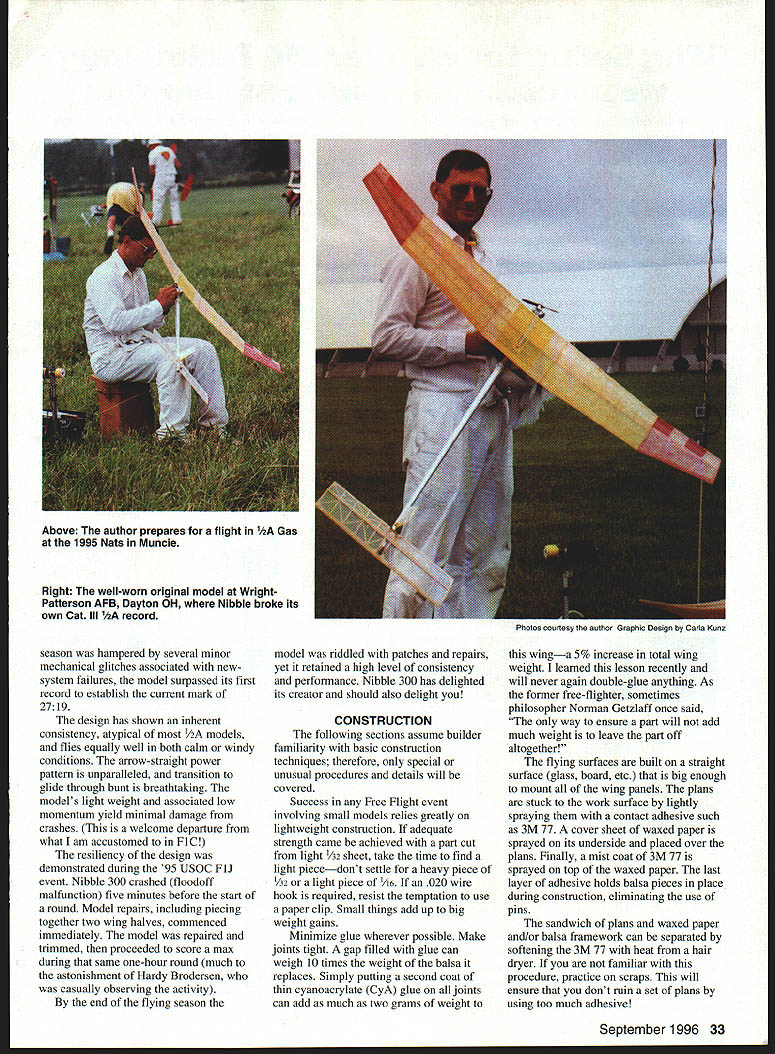
While the development of this model was lengthy by most standards, its rise to prominence was not. Nibble 300 captured a new Cat III 1/2A Gas record during its first contest—right off the board—at the Muncie flying site. This was no fluke. Although flying during its first contest at Wright-Patterson AFB, Dayton, OH, Nibble broke its own Cat III record the next season. Hampered by several minor mechanical glitches associated with the new system, the model surpassed its first record to establish a mark of 27:19.
The design has shown inherent consistency atypical of models its size; it flies equally well in calm and windy conditions. Its arrow-straight power pattern, unparalleled transition and glide through the bunt are breathtaking. The model's light weight and associated low momentum yield minimal damage in crashes—a welcome departure from the heavy resilience required in F1C models.
The design was demonstrated during the 1995 USOC F1J event. Nibble 300 crashed as the result of a flood-off malfunction five minutes before the start of a round. Model repairs, including piecing together two wing halves, commenced immediately. The model was repaired, trimmed, and proceeded to score a max during the same one-hour round, much to the astonishment of Hardy Brodersen, casually observing the activity. At the end of the flying season the model was riddled with patches and repairs, yet retained a high level of consistent performance. Nibble 300 has delighted its creator and should also delight others.
CONSTRUCTION
The following sections assume the builder's familiarity with basic construction techniques; only special or unusual procedures and details are covered.
Success in any Free Flight event involving small models relies greatly on lightweight construction. If adequate strength can be achieved with a part cut from light 1/32" sheet, take the time to find a light piece—don't settle for a heavy piece of 1/32" or a light piece of 1/16". A .020" wire hook is required; resist the temptation to use a paper clip. Small things add up to big weight gains.
Minimize glue wherever possible. Make joints tight. A gap filled with glue can weigh ten times the balsa it replaces. Simply putting a second coat of thin cyanoacrylate (CyA) glue on all joints can add as much as two grams to the wing—a 5% increase in total wing weight. From a lesson learned recently: I will never again double-glue anything. As the former free-flighter (and sometime philosopher) Norman Getzlaff once said, "The only way to ensure a part will not add much weight is to leave the part off altogether."
Flying surfaces are built on a straight surface (glass, board, etc.) big enough to mount all of the wing panels. Stick the plans to the work surface by lightly spraying contact adhesive such as 3M 77. Place a cover sheet of waxed paper (sprayed on its underside) over the plans. Finally, mist a coat of 3M 77 on top of the waxed paper. The adhesive layer holds balsa pieces in place during construction, eliminating the use of pins.
The sandwich of plans, waxed paper and balsa framework can be separated by softening the 3M 77 with heat from a hair dryer. If you are not familiar with this procedure, practice on scraps to avoid ruining a set of plans.
Wing
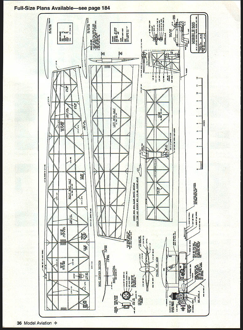
- The Nibble 300 has a five-section wing and uses a logarithmic-spiral airfoil. The five panels eliminate a center joint where the highest bending stress is concentrated. Multiple dihedral breaks allow easy tailoring of wood sizes and densities.
- Note and follow the wood densities indicated on the plans. The tapered, closed-box spar carries the majority of the bending and torsional loads. Use:
- Center spar wood: 8–10 lb/ft³
- Main spar wood: 6–8 lb/ft³
- Tip spar wood: 4–6 lb/ft³
- Other wing pieces: 4–6 lb/ft³ (these simply fair the airfoil)
- Use an 8% logarithmic-spiral curve to cut all straight ribs. This spiral has the unique characteristic that any radial curve emanating from the source will be geometrically similar—ribs of various lengths share this characteristic.
Wing construction sequence (overview):
- Cut and stick the wing spar bottom, leading edge, and trailing edge pieces to the building plan. Assure tight-fitting dihedral joints, but do not glue at this time.
- Cut six full-size ribs to the main pattern and glue them in place on the wing center section with thick CyA.
- For ribs in the tapered portions, cut to fit: place a full-size rib on the plan, mark the desired length, trim, then use a straightedge to mark leading and trailing edge heights and the main spar location. This produces shorter ribs similar in shape but reduced in size.
- Repeat for every rib in the tapered wing. Cutting ribs in pairs saves time.
- Glue all ribs, except those at dihedral joints, in place using thick CyA. While panels are on the plan, use a long sanding block to even out minor imperfections.
- Remove all five panels from the plans and join them at the proper dihedral angles. The partially built wing will be flexible—this is normal.
- Glue the straight dihedral ribs in place. Lay the structure flat on each consecutive panel and glue the main spar tops in place.
- Mark turbulator spar locations, notch ribs for the spars, and glue the spars in place.
- Install the main-spar vertical webs and dihedral gussets. Position and trim the half-depth cross braces so their thickness at the trailing edges matches the straight ribs already glued in place. With proper fit these cross-braces just touch the turbulator spar bottoms—gluing this joint adds considerable strength.
- Glue in place the cross ribs; the wing structure will now be complete.
Finish:
- Carve the leading edge, final-sand the top and bottom of the wing, and prepare to cover.
- Apply one coat of covering adhesive (Sig Stix-It recommended), allow to dry overnight, and cover with light, clear (white-appearing) Micafilm.
- Dye the inside of the covering with a Higgins Permanent Marker for a low-weight color variation.
- Seal all Micafilm joints with a 1/8" strip of MonoKote to increase seam durability.
- Use care to evenly apply and shrink Micafilm without introducing unwanted warps. During final shrinking ensure tip washout matches the plans. Tip washout (twist) is an asset—use about 3/16" washout at the tip. The washout is built into the wing during the dihedral gluing operation; final sanding and filling of gaps is required in this area before covering.
Your completed wing should be carefully weighed and balanced; aim to keep weight low without sacrificing strength.
Tail Surfaces
- The stabilizer and rudder are built over the plans using the 3M 77 hold-down technique. There is very little load on these structures; use 4–6 lb/ft³ wood.
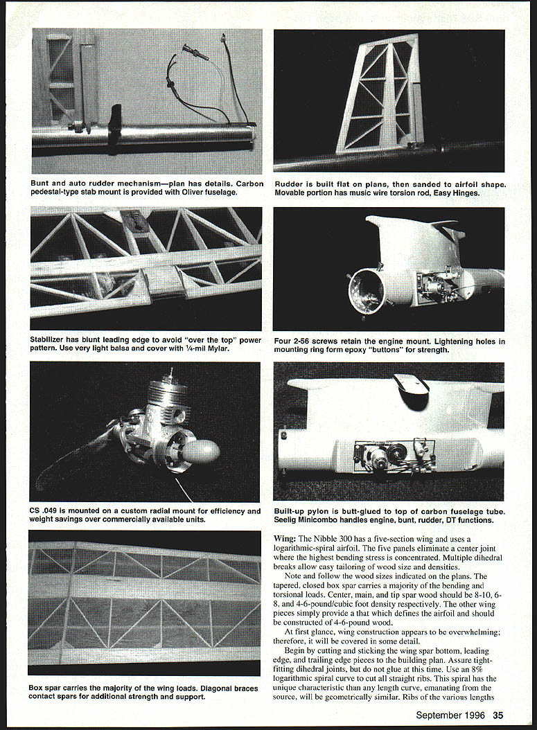
- Note the blunt shape of the stabilizer leading edge. Stabilizer leading edge radius has been directly linked to the "over the top" phenomenon. The bluntness increases drag but yields a more consistent power pattern.
- Carefully drill and align the bunt hold-down piece of 1/64" plywood. Glue this piece to the stabilizer top surface and leave the bottom open to allow maximum glue clearance for the glue and bunt posts.
- The rudder is built on the plans with no airfoil shape; carve and sand to a symmetrical section after structure completion.
- Use easy hinges to secure the rudder tab; a buried music wire torsion rod transmits movement to the glide position. Rudder position stops are provided by 2-56 socket-head bolts secured to the fuselage by a part formed from 1/4" plywood.
- Rudder tab position must be very positive for consistent power adjustments.
- Cover both stabilizer and rudder with 1/4-mil Mylar. Upon final shrinking ensure warp-free surfaces.
Fuselage
- The Oliver boom has proven crash-tough on the original Nibble 300; if the fuselage survives a crash, the model can generally be repaired in the field and returned to flying the same day.
- Ken Oliver provides an insert doubler to reinforce and mount the timer and a small lightweight stabilizer rest. This system simplifies fuselage work.
- Build a pylon and butt-glue it to the carbon tube with 3M DP-460 epoxy (industrial-grade product available through 3M distributors). Drill some 1/8" holes in the top of the fuselage where it mates with the pylon so epoxy will run into the holes and form "buttons" to help hold the pylon. Reinforce with a fillet of microballoons and 5-minute epoxy.
- Both motor tube and tailboom must be shortened for the Nibble 300. Leave the nose length longer than indicated during the initial build. Final nose length is determined by assembling the nearly-complete model and determining the center of gravity (CG). Trim the nose until a proper CG is obtained.
- Secure the engine hold-down sleeve to the inside front of the tube using DP-460 epoxy. This sleeve interfaces with the custom-turned backplate, providing a very light engine mount. The mounting ring inserted in the fuselage has many lightening holes; when epoxy fills these holes it acts as buttons locking the ring to the carbon tube. This style mount has survived severe crashes on engines from .049 to .40.
- Secure the rudder, stabilizer rest, and VIT (Variable Incidence Tailplane) mechanism holder with 3M DP-460. Rudder alignment is critical; use calipers to align leading and trailing edges. Stab tilt is provided by the angular position of the stabilizer rest.
- Attach the wing to the pylon, measure correct tilt, and glue in place.
- Finish the front fuselage with three coats of Super Poxy filler, sanding thoroughly between coats. Remove approximately 80% of filler by thorough sanding. Spray the final coat of filler and sand lightly with 600-grit before spraying a final color coat. Use Super Poxy paint sparingly—paint can build up weight quickly. A light topcoat of thinned clear Super Poxy will give a brilliant shine.
Variations and Development
- A second wing was built featuring a 9% mid-section logarithmic-spiral airfoil tapering to 7% at the tips. The mid-section thickness increase (and associated strength increase) allowed a lighter structure. Complexity and weight were reduced by omitting the cross-ribs (they can be added later if required). This alternative wing weighs about 48 grams and will be evaluated with back-to-back testing on the common fuselage.
- Other design changes that might be considered: smaller tail volumes (shorter tailboom or less stab area), a higher wing aspect ratio, and further lightening of the fuselage front tube by sanding or by negotiating a lighter carbon lay-up with the supplier.
- For application to an F1J model with a .061 engine, scale the design up to 380 square inches. Most Kinko’s (or similar services) can enlarge 40" drawings for a nominal cost.
The Nibble 300 will make an impressive addition to your stable of power models. Every attempt has been made to accurately document the design so duplicates can be built. Special thanks to Don Simpkins, whose computer skills developed the plans set.
FINAL ASSEMBLY
At this point your model is about 95% complete, but avoid the urge to rush final assembly and rigging.
- The brain of your model is the timer. A significant percentage of this model's weight is in the Seeling Minicombo timer. Plastic Tomy-type timers were considered but rejected for reliability reasons. Auto-surface functions, bunt and flood-off timing are critical for Cat. III engine runs.
- Make all control lines from lightweight monofilament. There is very little load on lines for small models. Lightweight monofilament is stretchy; the stretch eliminates the requirement for springs but is temperature-variable. The original Nibble 300 was flown all season without breaking or changing a line.
- Since there is no tailboom joint, rigging is accomplished by threading a feeder line through the rear of the fuselage and the front exit holes to the timer compartment (possible because there are no bulkheads aft of the timer). Join the two feeder lines and use them to pull in all control lines.
- Check all variable functions 20 times in your shop. Become comfortable adjusting stabilizer and rudder. Set the initial power position for 0° wing-to-stab alignment. Add 1/8" trailing-edge negative (up) for the initial glide position. Check DT angle and set your timer for a two-second flood-off and quick DT (just after flood-off).
Belabor the final details to ensure a successful first flying session. If you are rushing to meet an imminent contest, re-evaluate your schedule. No one can afford to rebuild because of an avoidable error.
Flying
- Begin with a series of test glides with the stab set in the glide position, then in the power position. The objective is a floating glide with a gentle right turn and a shallow straight dive under power.
- If unsure, take a trimmed model and hand-toss in the power position to develop confidence in the idea of a shallow dive.
- Run your engine several times to ensure consistency and test your two-second flood-off setting. Flood-off reliability is essential for initial flights since power trim has not yet been obtained.
- Launch your first flight straight up under full power. If you followed the procedure and have no mechanical failures, an event-free first flight is likely.
- Gradually increase engine runs, trimming for a straight-up climb with a slight right roll to position the model into the thermal (often located to the right of the launch).
- The first gliding flight should be done with the DT set at 20 seconds to provide DT altitude margin if glide trim is off or a malfunction occurs.
Engine/prop notes:
- The initial 1/2A record was set with a Poti's Hangar 5.7" x 2.7" prop running on 50% nitro at 27,000 rpm. The engine was difficult to tune in this configuration.
- After exhaustive rework of the fuel system and head clearances proved fruitless, Ed Keck discovered that "unloading" the engine by trimming prop diameter to 5.4" provided the desired consistency. This reworked prop increased rpm to 28,500 and observers noted a significant increase in altitude with the smaller-diameter prop which was used to set the second record.
Nibble 300 has great potential in the hands of an experienced flier. It can achieve all but the four-second engine run, 150-second max easily. Both competitors and spectators enjoy the spectacular performance of this model.
A collection of Nibble 300 photos will be assembled; please send a photo of your model. Both you and I will be pleased once your Nibble 300 is airborne and collecting hardware. Thermals!
Norman D. Poti 5695 Marshall Rd. Dayton, OH 45429-6022
Transcribed from original scans by AI. Minor OCR errors may remain.

