
Niblite 584
This Class B free-flight model for Category III has done it all.
Norman D. Poti
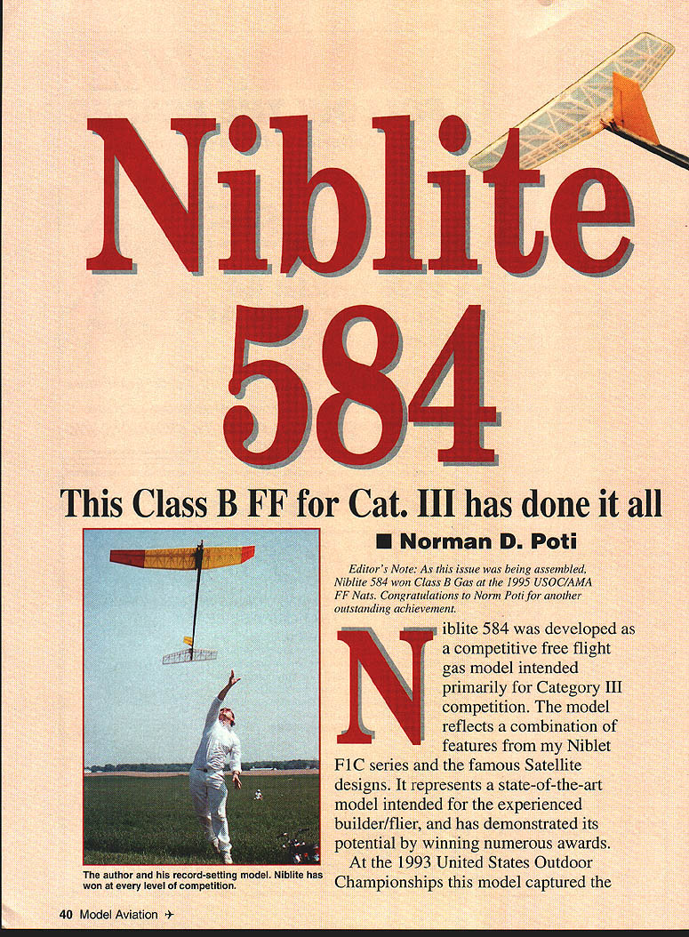
Editor's Note: As this issue was being assembled, Niblite 584 won Class B Gas at the 1995 USOC/AMA FF Nationals. Congratulations to Norm Poti for another outstanding achievement.
Niblite 584 was developed as a competitive free-flight gas model intended primarily for Category III competition. The model reflects a combination of features from my Niblet F1C series and the famous Satellite designs. It represents a state-of-the-art model intended for the experienced builder/flier and has demonstrated its potential by winning numerous awards.
At the 1993 United States Outdoor Championships this model captured the Category III national record, completing 33 maxes for a total of 80 minutes. That accomplishment represents a pinnacle in my 29-year free-flight career and resulted in Niblite's selection as a National Free Flight Society (NFFS) Model of the Year.
The objective was to build a lightweight 600-square-inch model that could handle the powerful O.S. Max .25 ducted fan engine. Long tail moment and ample dihedral lead to a very stable and consistent model that is flown with auto-rudder and auto-stab, but without bunt. At 752 grams (26.5 ounces) Niblite accelerates quickly under power — a quality essential for four-second Category III flyoff flights — and provides a very buoyant glide.
Niblite weighs the same as an F1C but has 100 more square inches in the wing, 80% more displacement, and is flown on 60% nitro.
The 584 was first flown in 1990. The original wing was built with an open main spar, no vertical webs, and was covered with Micafilm. That wing weighed 188 grams and was flown for one contest season, but proved to be too flexible; it could handle bending loads, but was too weak in torsion. The wing would wash out and provide a bunt-like pattern on long engine runs with the stab fixed. While this aeroelastically induced bunt concept was intriguing, consistency could not be achieved. The wing was stripped, vertical spar webs were added, and the wing was re-covered with MonoKote. The rebuilt wing weighed about 41–49 grams heavier and produced a very stable configuration.
Wing and stabilizer utilize 9% and 6% Simplex flat-bottom airfoils, respectively. The airfoils are based on a logarithmic spiral which produces a curve geometrically similar to the original at any scale. This property is invaluable when building a tapered wing, as it allows ribs to be cut from a master rib curve. A combination of airfoils, a 25% stabilizer set, and a 34-inch moment produces a very stable power pattern. The lightly loaded wing yields an impressively slow glide.
Specifications
- Type: FE Class B
- Wingspan: 71-1/2 inches (flat)
- Wing area: 584 square inches
- Engine: O.S. Max .25 ducted fan
- Flying weight: 26.5 ounces (752 grams)
- Construction: Built-up
- Covering/finish: MonoKote, Mylar
Construction
Anyone attempting to build this model should be familiar with basic construction; only unusual techniques and procedures are provided here.
Wing
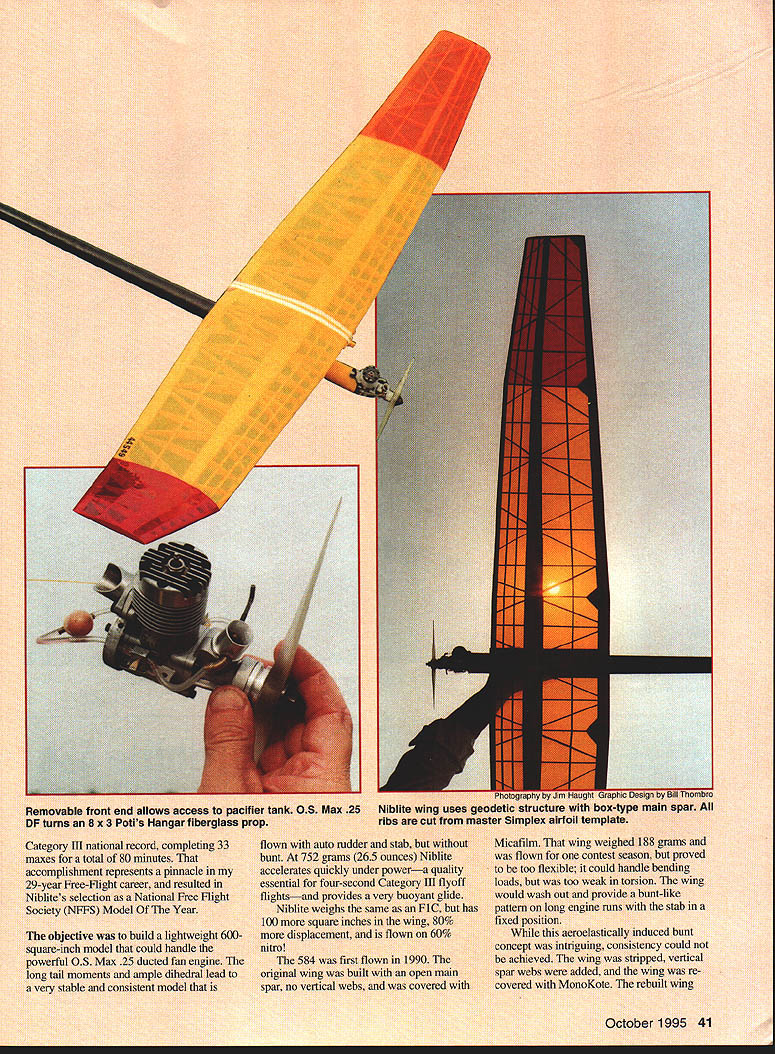
At first glance the wing construction appears overwhelming; therefore it is covered in detail. The wing is built in five parts, which eliminates the typical center joint and associated stress concentration. Major bending and torsional loads are carried by a closed, fully tapered box spar. The spar is built as a single unit instead of being assembled only as an integral part of the wing. This technique allows the straight diagonal ribs to carry through the spar.
The five-panel layout produces four dihedral joints. Wood sizes and densities can be tailored to minimize weight while still carrying loads. Note and follow the wood sizes indicated on the plans:
- Center spar wood: 8–10 lb/cu ft
- Main spar wood: 6–8 lb/cu ft
- Tip spar wood: 4–6 lb/cu ft
- All other wing components: 4–6 lb/cu ft (these carry little load and primarily define airfoil shape)
The wing is built on a straight board large enough to mount all panels. The board is lightly sprayed with 3M 77 contact adhesive and the plans are stuck to the board. If unfamiliar with this technique, practice sticking and removal with scraps. The plans are sprayed with 77 and covered with waxed paper; then the waxed paper is sprayed with 77. This last layer holds parts in place while assembling and permits fast construction without pins.
Construction sequence (overview):
- Stick the spar bottom, leading edge, and trailing edge bottom to the plans. Assure tight-fitting dihedral joints but do not glue them yet. Cut and glue the center section straight ribs in place.
- Use the main wing rib pattern to cut six ribs for the center section. For tapered portions, trim full-size ribs to fit using the cut-to-fit method: place a full rib on the plan with its leading edge set, mark and cut the trailing edge to length, then slice along the bottom surface with a straightedge to form the new rib bottom. Mark and cut the main spar and trailing edge locations. Repeat for each rib in the tapered portion, cutting ribs in pairs (one per wing half).
- Glue all straight main panel ribs (except at dihedral joints) in place with thick cyanoacrylate (CyA). Use a long sanding block to even out minor imperfections while panels are still on the plans.
- Remove panels from the plans and join them at the proper dihedral angles. A hair dryer will soften the 3M 77 if panels are stuck to waxed paper.
- CyA the straight dihedral ribs in place. Lay the partially built structure flat and, starting with the center section, cut, fit, and glue diagonal ribs. Use the rib-cutting procedure above but follow diagonal lengths and spar-center thickness for dimensions. Tight joints at the main spar intersection add considerable strength.
- Sand diagonal ribs as needed so airfoil contour is smooth and consistent.
- CyA the spar tops and trailing edge tops in place. Notch the ribs and install stringer spars per the plans.
- Lift the wing from the board and glue the other side of the spar in place. Ensure the wing is not twisted. After the second side is glued, allow to dry, remove excess CyA, and sand smooth.
- Join the center section box to the outer panels using 1/8-inch balsa shear webs bonded with aliphatic resin glue. Cut shear webs to fit the taper and bond into main spar slots—check for full contact. Glue main spar caps, sand lightly, and coat spar caps with thin CA for added strength.
- Install main spar vertical webs, trailing edge cap, and dihedral gussets to close the box spar. Carve the leading edge shape, final-sand the top and bottom of the wing, and prepare to cover.
Covering: Transparent MonoKote is preferred. Evenly apply and shrink without introducing warps. During covering, wash-in the right main panel 3/32 inch and wash-out each tip 1/8 inch. The completed wing should weigh about 237 grams and be very strong.
Tail Surfaces
The stabilizer is built over the plans using the 3M 77 hold-down method. There is very little load on the stabilizer, so use only 4–6 lb. wood. All ribs are made using the cut-to-fit method described for the wing.
- Finish the stab framework with one coat of Balsarite and cover with 1/2-mil clear Mylar. Seal leading and trailing edges with 3/16-inch strip of clear MonoKote (Balsarite is not fuelproof).
- The rudder frame is built up and covered with 1/32 light balsa. The peg that extends into the fuselage is a 3/16 hardwood dowel, providing strength for the rudder-fuselage joint.
- Rudder tab movement uses Sig Easy Hinges thin-CyAed in place; a torsional rubber spring provides movement into the glide position. Rudder position stops use 2-56 socket-head bolts. The rudder tab position must be very positive for consistent power adjustments.
- Cover rudder and tab with transparent MonoKote.
Fuselage
The fuselage is built around a commercially available carbon tube manufactured for modeling use. The tube is cut to length and used as the main fuselage structure.
- Several tube sources are listed in the Source List. Ken Oliver’s aluminum/carbon/aluminum system is popular; Ken also produces an insert doubler used to reinforce and mount the timer.
- The pylon is glued to the tube with 3M DP-460 epoxy. Fillet the pylon-fuselage joint with a 5-minute epoxy/microballoon mixture.
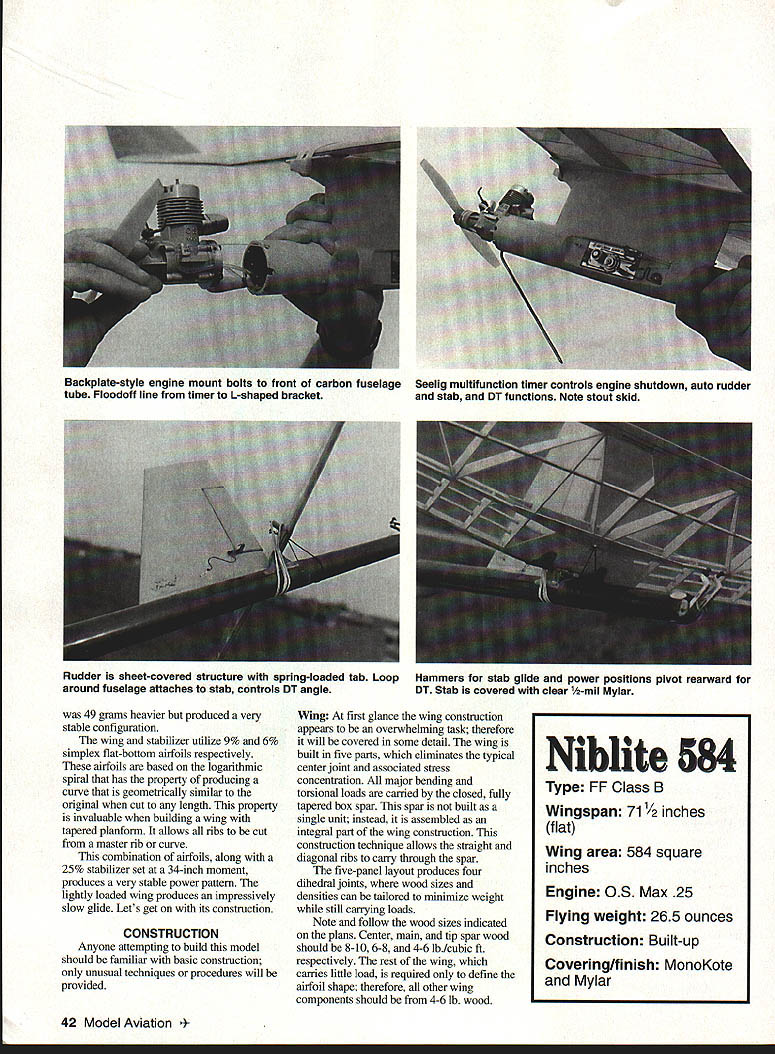
- The engine is mounted using the backplate bolt holes. The mount and sleeve insert are custom-turned, producing a light system. The mounting ring inserted into the carbon tube has many 1/8-inch lightening holes; these form glue buttons that lock the ring to the tube. If you do not have lathe access, Dub McCormick will turn parts to your specifications.
- The rudder, stab rest, and variable incidence tailplane (VIT) arms are secured with 3M DP-460 epoxy.
Rudder alignment is critical: hold the fuselage securely and use calipers to align the rudder leading edge with the stabilizer. Use small shims to fine-tune alignment and ensure the rudder is true fore and aft.
Timer and servo installations are conventional. The Seelig multifunction timer controls engine shutdown and auto-rudder functions. The L-shaped bracket provides stab/DT functions. Note the stout skid. The rudder sheet-covered structure and spring-loaded tab are installed as shown on the plans. Loop the spring around the fuselage and attach the stab controls. The DT (dethermalizer) angle hammers the stab into glide and power positions; pivot the rearward DT as shown. The stabilizer is covered with clear 1/2-mil Mylar.
Stab tilt is provided by the position of the stab rest. Attach the wing to the fuselage and epoxy the stab rest in place with the proper glue.
Begin finishing the front of the fuselage with three coats of Super Poxy filler, sanding thoroughly between coats. Spray a final coat of filler and sand lightly with 600-grit paper before spraying a final coat of color. Use Super Poxy paint sparingly, as it can add weight quickly. A light coat of thinned clear Super Poxy will give the fuselage a brilliant shine.
Final Assembly
At this point the model is about 95% complete, but the most important part of the building is yet to come. Extreme care must be given to rigging and final assembly details—this care will make the model safe and consistent.
The timer is the brain of the model and controls engine run, auto-rudder, auto-stab, and dethermalizer. Doug Galbreath provides a procedure for modification and care of all Seelig timers—follow it exactly. More free-flight models are demolished or lost by timer-related failures than by any other source.
Rigging and checks:
- Use .015 control line cable for the control lines. Terminate rigging lines so they do not catch on wire-arm corners. Ensure the DT wire does not catch on the winding-scroll handle (the handle can be eliminated if a winding tool is used).
- Ensure the floodoff system is flawless—one failure and the airplane is gone.
- Make sure stab power and glide positions are positive and that lines apply enough tension to properly set stabilizer and rudder.
- Check VIT arm travel to assure they move away from the stabilizer completely.
- Set the DT angle as shown on the plans and ensure lines do not tangle or limit full travel.
- Set all timer functions and test both quick-DT and full-flight modes at least 20 times in the shop. Resolve any failure mode now.
- Set stabilizer position to 0° relative to the wing for the power setting. Set the glide position to 2° relative to the wing.
Once this setup is completed you can go to the flying field with confidence that you will return with your model intact.
Flying
Begin the first flying session with a series of test glides with the stab and rudder in glide positions. The objective is a floating glide with a gentle right-hand turn.
Continue with test glides in the power position. The objective is a shallow, perfectly straight dive. If unfamiliar with this procedure, take a trimmed model and glide it in the power setting to get experience. Set the timer for a two-second engine run with a quick-DT one second later. Run the engine on the ground until it runs consistently, testing the floodoff and quick-DT on the ground at least four times. Only then attempt the first flight.
For the first flights:
- Reset the timer and launch straight up for a two-second run and a quick DT. Gradually increase engine runs, trimming for a straight-up climb with a slight roll to the right.
- For the first gliding flight set the DT for only 20 seconds to allow a DT with plenty of altitude in case the glide position is off or the glide function malfunctions. If satisfactory, "dial in" the glide with longer flights.
Powerplant and propeller: The 584 is powered by a stock O.S. Max .25 ducted fan engine. Using 60% nitro, the engine turns a Poti's Hangar 8 x 3 fiberglass propeller at about 23,000 rpm. Never use a plastic or wood prop on an engine of this potential—safety is paramount.
This model draws attention every time it is flown; competitors and spectators enjoy its spectacular performance. All but final flyoff flights can be attained without thermal help.
Possible design improvements to consider:
- Decrease wing thickness to 8%
- Lower stabilizer area to about 20%
- Shorten and thin the pylon
- Use a smaller-diameter carbon tube
- A meticulous builder might remove an additional 30–40 grams of weight
This design has been scaled up to a 750-square-inch C-D Gas model and scaled down to a 310-square-inch F1J size. These three sizes provide the author with a configuration for almost any AMA Gas event.
It has been gratifying to see the interest and accolades this model has garnered. Please contact me with questions or comments about construction or flying. You will remain impressed, and I will be pleased, once your Niblite 584 is airborne!
Norman D. Poti 5695 Marshall Rd. Dayton, OH 45429
Source List
Carbon Tubes
- Ken Oliver
2213 El Cojo Circle Rancho Cordova, CA 92041
- Bob Waterman
4480 Northwest Wallowa Ct. Portland, OR 97229
Custom Machining
- Dub McCormick
3800 Shellbrook Ave. Fort Worth, TX 76109
Seelig Timers
- Doug Galbreath
2810 Cowell Blvd. Davis, CA 95616
Transcribed from original scans by AI. Minor OCR errors may remain.

