
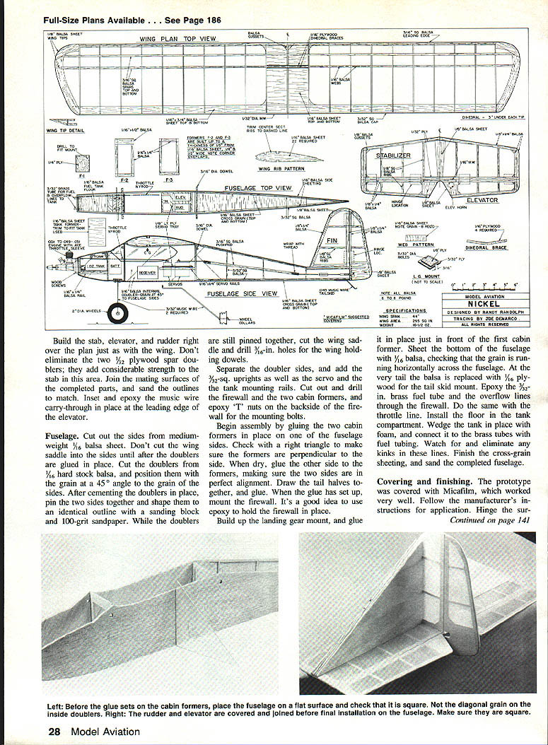
Nickel
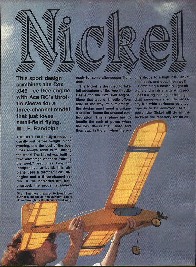
This sport design combines the Cox .049 Tee Dee engine with Ace RC's throttle sleeve for a three-channel model that just loves small-field flying. — L. F. Randolph
The best time to fly a model is usually just before twilight in the evening, and the best of the best times always seem to fall during the week. The Nickel was built to take advantage of those "during the week" best times. Easy and inexpensive to build, this airplane uses a throttled Cox .049 engine and a three-channel radio. If the batteries are kept charged, the model is always ready for some after-supper flight time.
The Nickel is designed to take full advantage of the Ace throttle sleeve for the Cox .049 engine. Since that type of throttle offers little in the way of a midrange, the design must meet a unique situation — hence the unusual configuration. This airplane has to handle the rush of power when the Cox .049 is at full bore, and then stay in the air when the engine drops to a high idle. The Nickel does both, and does them well.
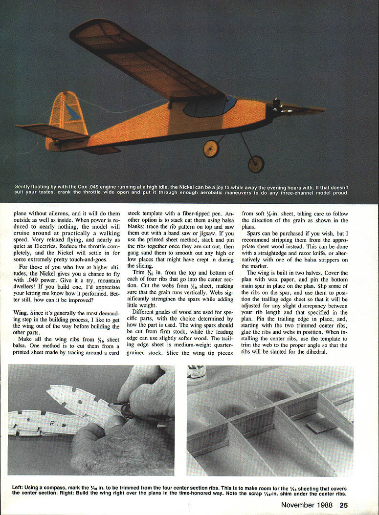
Combining a basically light airplane and a fairly large wing provides a wing loading in the single-digit range — an absolute necessity if a wide performance envelope is to be achieved. At full power the Nickel will do all the tricks in the repertory for an airplane without ailerons, and it will do them outside as well as inside. When power is reduced to nearly nothing, the model will cruise around at practically a walking speed. Very relaxed flying, and nearly as quiet as electrics. Reduce the throttle completely, and the Nickel will settle in for some extremely pretty touch-and-goes.
For those who live at higher altitudes, the Nickel gives you a chance to fly with .049 power. Give it a try, mountain dwellers! If you build one, I'd appreciate your letting me know how it performed. Better still, how can it be improved?
Wing
Since it's generally the most demanding step in the building process, I like to get the wing out of the way before building the other parts.
Make all the wing ribs from 1/16-in. sheet balsa. One method is to cut them from a printed sheet made by tracing around a card-stock template with a fiber-tipped pen. Another option is to stack-cut them using balsa blanks: trace the rib pattern on top and saw them out with a band saw or jigsaw. If you use the printed-sheet method, stack and pin the ribs together once they are cut out, then gang-sand them to smooth out any high or low places that might have crept in during the slicing.
Trim 1/16 in. from the top and bottom of each of four ribs that go into the center section. Cut the webs from 1/16-in. sheet, making sure that the grain runs vertically. Webs significantly strengthen the spars while adding little weight.
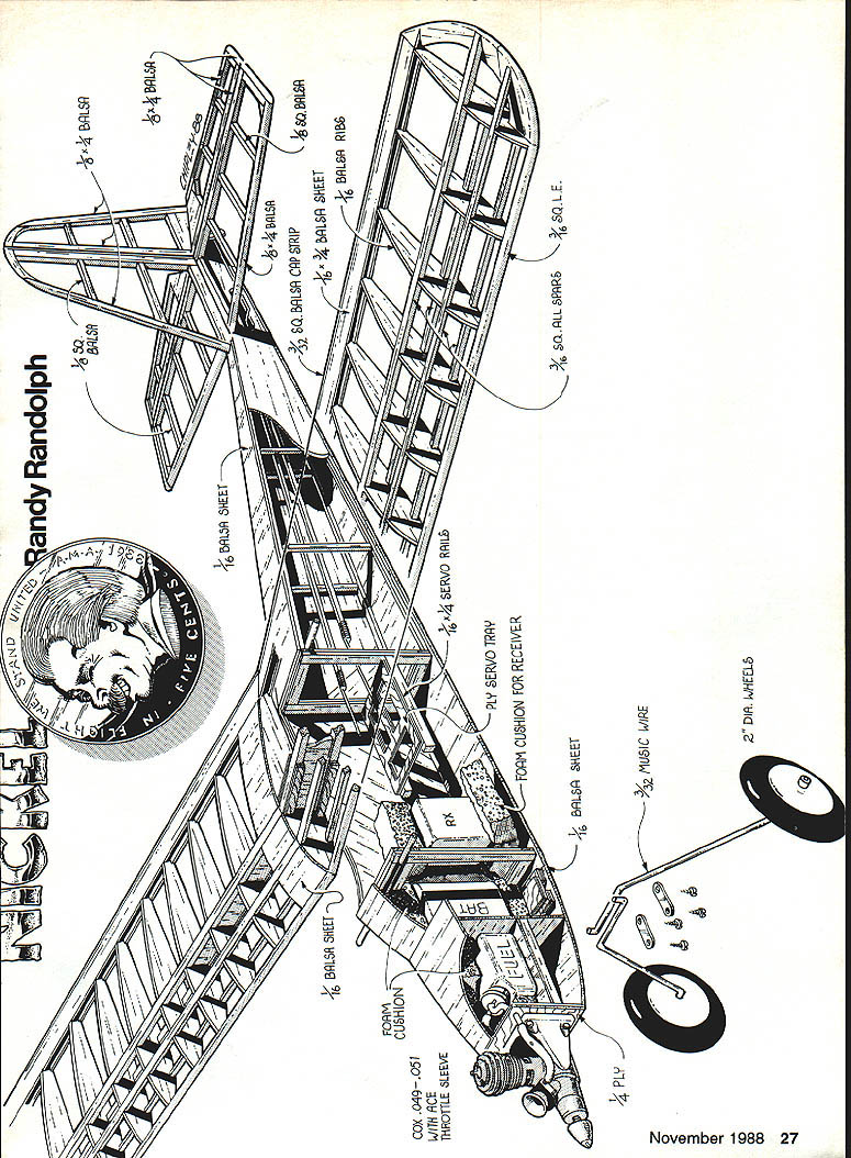
Different grades of wood are used for specific parts, with the choice determined by how the part is used. The wing spars should be cut from firm stock, while the leading edge can use slightly softer wood. The trailing-edge sheet is medium-weight quarter-grained stock. Slice the wing-tip pieces from soft 1/8-in. sheet, taking care to follow the direction of the grain as shown in the plans.
Spars can be purchased if you wish, but I recommend stripping them from the appropriate sheet wood instead. This can be done with a straightedge and razor knife, or alternatively with one of the balsa strippers on the market.
The wing is built in two halves. Cover the plan with wax paper, and pin the bottom main spar in place on the plan. Slip some of the ribs on the spar, and use them to position the trailing-edge sheet so that it will be adjusted for any slight discrepancy between your rib length and that specified in the plan. Pin the trailing edge in place, and, starting with the two trimmed center ribs, glue the ribs and webs in position. When installing the center ribs, use the template to trim the web to the proper angle so that the ribs will be slanted for the dihedral.
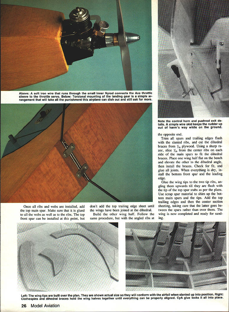
Trim spars and trailing edges flush and cut the slanted ribs. Cut dihedral braces from 1/16-in. plywood. Using a sharp razor, slice the 1/16-in. center ribs so the main spars fit the dihedral braces. Place one wing half flat on the bench, elevate the other at the dihedral angle and install the braces. Check the fit and glue the joints; when everything is dry, install the bottom front spar and the leading edge. Glue the wing tips (two tip ribs), gluing upwards until flush with the top spar stubs per the plans. Use scrap spar material to shim up the bottom main spars at the tips. Add the top trailing edge and the center-section sheeting, taking care that the sheeting goes between the spars rather than over them. The wing is now completed and ready for sanding.
Once all ribs and webs are installed, add the top main spar. Make sure that it is glued to all the webs as well as to the ribs. The top front spar can be installed at this point, but don't add the top trailing-edge sheet until the wings have been joined at the dihedral. Build the other wing half following the same procedure, but with the angled ribs at the opposite end.
Trim all spars and trailing edges flush with the slanted ribs, and cut the dihedral braces from 1/16-in. plywood. Using a sharp razor, slice 1/16 in. from the center ribs on each side of the main spars to fit the dihedral braces. Place one wing half flat on the bench and elevate the other to the dihedral angle, then install the braces. Check for fit, and glue all joints. When everything is dry, install the bottom front spar and the leading edge.
Glue the wing tips to the two tip ribs, angling them upwards till they are flush with the tip of the top spar stubs as per the plans. Use scrap spar material to shim up the bottom main spars and the tips. Add the top trailing edges and then the center-section sheeting, taking care that the latter goes between the spars rather than over them.
Left: Wing tips built over plan shown actual size will conform to airfoil slanted-up position.
Right: Clothespins and dihedral braces hold wing halves together until everything can be properly aligned. CyA glue locks place.
Above: A soft iron wire runs through a small inner nylon sleeve; the throttle pushrod connects to the sleeve on the Cox .049–.051.
Below: Torsional-mounting landing gear — a simple arrangement that will take the punishment the airplane can dish out. Note control horn/pushrod exit details. A simple wire skid keeps the rudder up and out of harm's way on the ground.
Build the stab, elevator, and rudder right over the plan just as with the wing. Don't eliminate the two 1/32-in. plywood spar doublers; they add considerable strength to the stab in this area. Join the mating surfaces of the completed parts, and sand the outlines to match. Inset and epoxy the music-wire carry-through in place at the leading edge of the elevator.
Fuselage
Cut out the sides from medium-weight 1/16-in. balsa sheet. Don't cut the wing saddle into the sides until after the doublers are glued in place. Cut the doublers from 1/16-in. hard stock balsa, and position them with the grain at a 45° angle to the grain of the sides. After cementing the doublers in place, pin the two sides together and shape them to an identical outline with a sanding block and 100-grit sandpaper. While the doublers are still pinned together, cut the wing saddle and drill 3/16-in. holes for the wing-holding dowels.
Separate the doubler sides, and add the 3/32-in. uprights as well as the servo and the tank-mounting rails. Cut out and drill the firewall and the two cabin formers, and epoxy 1/4-in. plywood "T" nuts on the backside of the firewall for the mounting bolts.
Begin assembly by gluing the two cabin formers in place on one of the fuselage sides. Check with a right triangle to make sure the formers are perpendicular to the side. When dry, glue the other side to the formers, making sure the two sides are in perfect alignment. Draw the tail halves together, and glue. When the glue has set up, mount the firewall. It's a good idea to use epoxy to hold the firewall in place.
Build up the landing gear mount, and glue it in place just in front of the first cabin former. Sheet the bottom of the fuselage with 1/16-in. balsa, checking that the grain is running horizontally across the fuselage. At the very tail the balsa is replaced with 1/16-in. plywood for the tail-skid mount. Epoxy the 3/32-in. brass fuel tube and the overflow lines through the firewall. Do the same with the throttle line. Install the floor in the tank compartment. Wedge the tank in place with foam, and connect it to the brass tubes with fuel tubing. Watch for and eliminate any kinks in these lines. Finish the cross-grain sheeting, and sand the completed fuselage.
Covering and finishing
The prototype was covered with Micafilm, which worked very well. Follow the manufacturer's instructions for application. Hinge the surfaces using whatever method you're most familiar with.
Trim the covering away from the stab where it contacts the fuselage on the bottom and the rudder on the top. Epoxy the fin and rudder to the top of the stab, checking alignment with a square, and then epoxy the stab to the fuselage. Trim the covering away, then epoxy the 1/16-in. wing-mounting dowels in place. Epoxy the tail skid to the 1/16-in. plywood mount.
The engine mount is attached to the firewall with wood screws. Before doing so, harden the screw holes with thin CyA and paint the firewall with a coat of epoxy. Once the engine is mounted, attach the fuel line to the carburetor, then run a piece of soft iron wire through the throttle nylon sleeve to connect the latter to the throttle arm. Bend the landing-gear legs, add the wheels, and install the units in the gear mount with metal brackets and small wood screws.
Check that the plane balances at the point indicated on the plans, moving the battery pack and servos around as necessary. Install the radio, and recheck the balance point. Connect the elevator and rudder to the servos with pushrods made from soft 1/16-in. wire as shown. Make a "Z" bend in the throttle wire to engage the servo. Satisfy yourself that everything reacts properly to the transmitter controls, and do a range check. With that accomplished, your airplane is ready to fly.
Flying
The prototype has so far only been acquainted with rough and weedy fields. Most of the time I've flown her from a hand launch. Actually, not much of a throw is required to get the Nickel on its way. A wings-level, nose-on-the-horizon, baseball pitch does the job quite well.
Once she's in the air, trim the Nickel for level flight at full throttle. In this configuration, low-speed trim will still be well within the range of the trim lever on the transmitter.
The performance envelope will surprise you. Control response is positive and solid, like that of a much larger airplane. The Nickel's combination of light wing loading and throttle control lets the flier range from an almost straight-up climb to a quiet cruise — from fast and peppy to slow, gentle, and sedate.
Rolls aren't as smooth as with an aileron-equipped model—this is a rudder airplane, after all—but they unmistakably are rolls. Inverted flight is smooth and easy, even at reduced throttle, and outside loops are just as tight as inside ones. During taxiing, the rudder is quite effective for directional control without the need for a tail wheel. Finally, on a smooth field you can have great fun putting the Nickel through touch-and-go maneuvers.
The next time that after-supper urge to go flying strikes, you couldn't take along a better bet than a Nickel. It's the perfect antidote for those middle-of-the-week jangled nerves — fun, versatile, and maybe even a little daring. This model keeps you alert, on your toes, and ready for more fun. And what it does for me, it can do for you — help you make those best times even better!
Transcribed from original scans by AI. Minor OCR errors may remain.

