
Nieuport's Marvelous Monoplanes
Nieuports even prior to WW I were scientifically designed machines with extraordinary performance for their day.
This rubs off on our all-balsa CO2-powered model.
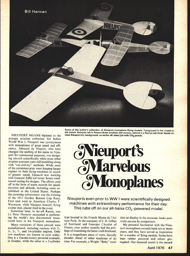
NIEUPORT MEANS biplanes to the average aviation enthusiast but before World War I, Nieuport was synonymous with monoplanes of great speed and efficiency. Edouard de Nieuport, who later changed the spelling of his name to Nieuport for commercial purposes, was designing aircraft scientifically while most other aviation pioneers were still bumbling along with "cut-and-try" methods. While most of his contemporaries were hanging larger engines on their flying machines in search of greater speed, Edouard was working with Gustave Eiffel (of tower fame) wind-tunnel testing his designs. The efforts paid off in the form of many records for speed, duration and altitude, including some established in the United States. Perhaps the crowning achievement was the winning of the 1911 Gordon Bennett Cup Race. First spot went to American Charles T. Weymann, while Nieuport himself, flying a sister ship, placed third in the event.
Sometime later, in far-off Russia, one Lt. Peter Nesterov succeeded in performing the world's first documented intentional loop in his Nieuport monoplane.
Many variations of these aircraft were manufactured, including versions with 2-, 3-, 5-, 7- and 14-cylinder engines. Only two machines are known to exist today. One is a Gnome-rotary powered example in Sweden, while the other is a 2-cylinder type located in the French Musee de l'Air near Paris. In the company of J. D. Gillies of Scotland and Georges Chaulet of France, your author recently had the privilege of examining the latter craft firsthand. It is a magnificent piece of work, literally decades ahead of other machines of its time. For example, a Wright "Baby" racer also on display in the museum looks positively ancient by comparison.
My personal fascination with the Nieuport monoplanes extends back ten or more years, and they have served as inspiration for a number of flying models. Some have been rubber powered and others glow-engined. Our featured model is the second PLAN REPRODUCED HERE IS PERFECT FOR PEANUT SCALE!
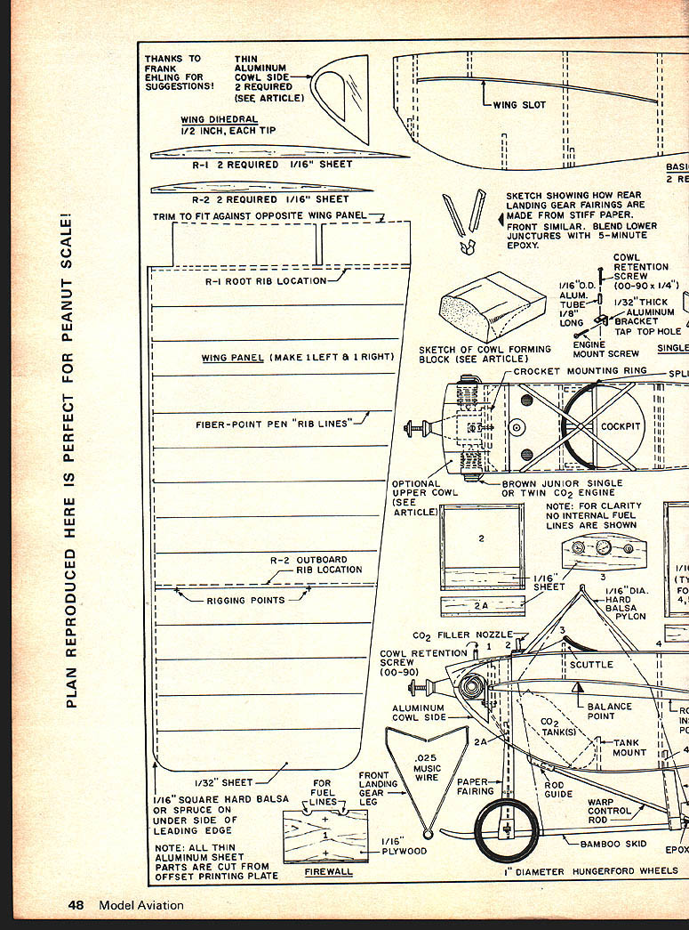
THANKS TO FRANK EHLING FOR SUGGESTIONS!
THIN ALUMINUM COWL SIDE — 2 REQUIRED (SEE ARTICLE)
WING DIHEDRAL 1/2 INCH, EACH TIP
R-1 2 REQUIRED 1/16" SHEET
R-2 2 REQUIRED 1/16" SHEET
TRIM TO FIT AGAINST OPPOSITE WING PANEL
R-1 ROOT RIB LOCATION
WING PANEL (MAKE 1 LEFT & 1 RIGHT)
FIBER-POINT PEN "RIB LINES"
R-2 OUTBOARD RIB LOCATION
RIGGING POINTS
1/32" SHEET
1/16" SQUARE HARD BALSA OR SPRUCE ON UNDER SIDE OF LEADING EDGE
NOTE: ALL THIN ALUMINUM SHEET PARTS ARE CUT FROM OFFSET PRINTING PLATE
SKETCH SHOWING HOW REAR LANDING GEAR FAIRINGS ARE MADE FROM STIFF PAPER. FRONT SIMILAR. BLEND LOWER JUNCTIONS WITH 5-MINUTE EPOXY.
SKETCH OF COWL FORMING BLOCK (SEE ARTICLE)
1/16" O.D. ALUM. TUBE 1/8" LONG
1/32" THICK ALUMINUM BRACKET — TAP TOP HOLE
COWL RETENTION SCREW (00-90 x 1/4")
ENGINE MOUNT SCREW
CROCKET MOUNTING RING
COCKPIT
OPTIONAL UPPER COWL (SEE ARTICLE)
BROWN JUNIOR SINGLE OR TWIN CO2 ENGINE
NOTE: FOR CLARITY NO INTERNAL FUEL LINES ARE SHOWN
1/16" SHEET
1/16" DIA. HARD BALSA PYLON
CO2 FILLER NOZZLE
COWL RETENTION SCREW (00-90)
ALUMINUM COWL SIDE
BALANCE POINT
CO2 TANK(S)
TANK MOUNT
FRONT LANDING GEAR LEG
.025 MUSIC WIRE
PAPER FAIRING
ROD GUIDE
1/16" PLYWOOD
FIREWALL
1/16" BAMBOO SKID
WARP CONTROL ROD
BALSA ROD GUIDE
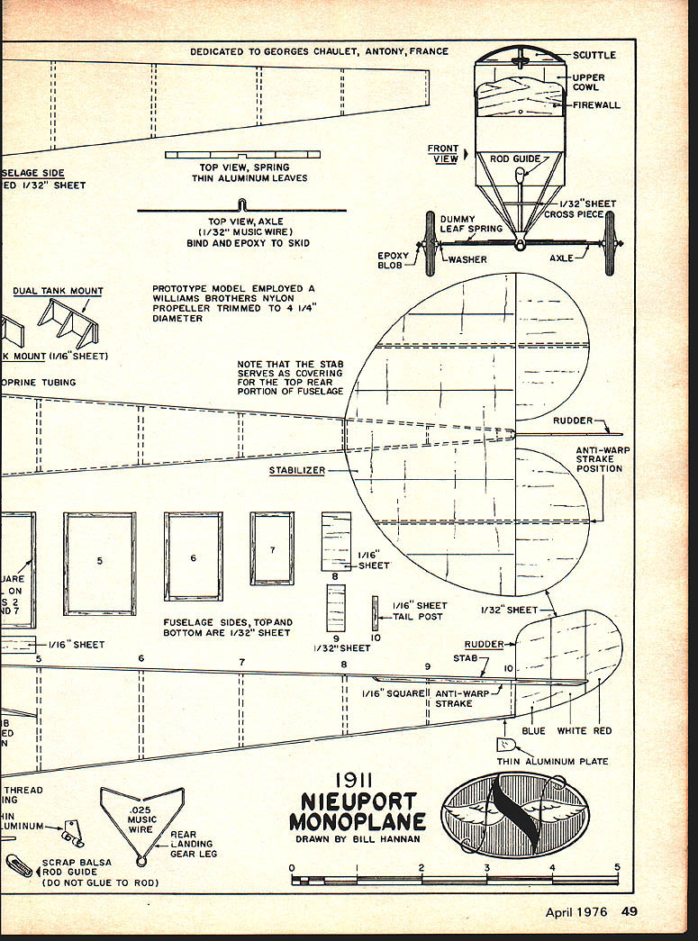
1" DIAMETER HUNGERFORD WHEELS DEDICATED TO GEORGES CHAULET, ANTONY, FRANCE
TOP VIEW, SPRING — THIN ALUMINUM LEAVES
FRONT VIEW
SCUTTLE UPPER COWL FIREWALL
ROD GUIDE
1/32" SHEET CROSS PIECE
DUMMY LEAF SPRING EPOXY BLOB WASHER AXLE
TOP VIEW, AXLE (1/32" MUSIC WIRE) BIND AND EPOXY TO SKID
DUAL TANK MOUNT
PROTOTYPE MODEL EMPLOYED A WILLIAMS BROTHERS NYLON PROPELLER TRIMMED TO 4-1/4" DIAMETER
K MOUNT (1/16" SHEET)
NOTE THAT THE STAB SERVES AS COVERING FOR THE TOP REAR PORTION OF FUSELAGE
STABILIZER
RUDDER
ANTI-WARP STRAKE POSITION
1/16" SHEET
FUSELAGE SIDES, TOP AND BOTTOM ARE 1/32" SHEET
1/16" SHEET TAIL POST 1/32" SHEET
RUDDER STAB
1/16" SQUARE ANTI-WARP STRAKE
BLUE WHITE RED
THIN ALUMINUM PLATE
SCRAP BALSA ROD GUIDE (DO NOT GLUE TO ROD)
.025 MUSIC WIRE REAR LANDING GEAR LEG
1911 NIEUPORT MONOPLANE
DRAWN BY BILL HANNAN
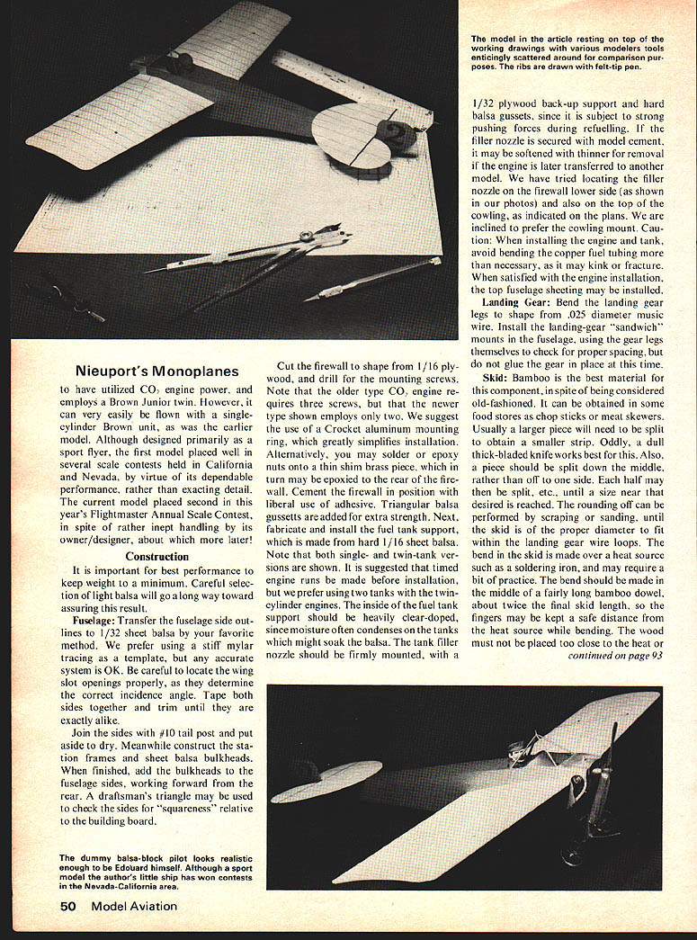
Nieuport's Monoplanes
to have utilized CO2 engine power, and employs a Brown Junior twin. However, it can very easily be flown with a single-cylinder Brown unit, as was the earlier model. Although designed primarily as a sport flyer, the first model placed well in several scale contests held in California and Nevada, by virtue of its dependable performance, rather than exacting detail. The current model placed second in this year's Flightmaster Annual Scale Contest, in spite of rather inept handling by its owner/designer, about which more later!
Construction
It is important for best performance to keep weight to a minimum. Careful selection of light balsa will go a long way toward assuring this result.
Fuselage: Transfer the fuselage side outlines to 1/32" sheet balsa by your favorite method. We prefer using a stiff Mylar tracing as a template, but any accurate system is OK. Be careful to locate the wing slot openings properly, as they determine the correct incidence angle. Tape both sides together and trim until they are exactly alike.
Join the sides with #10 tail post and put aside to dry. Meanwhile construct the station frames and sheet balsa bulkheads. When finished, add the bulkheads to the fuselage sides, working forward from the rear. A draftsman's triangle may be used to check the sides for "squareness" relative to the building board.
Cut the firewall to shape from 1/16" plywood, and drill for the mounting screws. Note that the older type CO2 engine requires three screws, but that the newer type shown employs only two. We suggest the use of a Crockett aluminum mounting ring, which greatly simplifies installation. Alternatively, you may solder or epoxy nuts onto a thin shim brass piece, which in turn may be epoxied to the rear of the firewall. Cement the firewall in position with liberal use of adhesive. Triangular balsa gussets are added for extra strength. Next, fabricate and install the fuel tank support, which is made from hard 1/16" sheet balsa. Note that both single- and twin-tank versions are shown. It is suggested that timed engine runs be made before installation, but we prefer using two tanks with the twin-cylinder engines. The inside of the fuel tank support should be heavily clear-doped, since moisture often condenses on the tanks which might soak the balsa. The tank filler nozzle should be firmly mounted, with a 1/32" plywood back-up support and hard balsa gussets, since it is subject to strong pushing forces during refuelling. If the filler nozzle is secured with model cement it may be softened with thinner for removal if the engine is later transferred to another model. We have tried locating the filler nozzle on the firewall lower side (as shown in our photos) and also on the top of the cowling, as indicated on the plans. We are inclined to prefer the cowling mount. Caution: When installing the engine and tank, avoid bending the copper fuel tubing more than necessary, as it may kink or fracture. When satisfied with the engine installation, the top fuselage sheeting may be installed.
Landing Gear
Bend the landing gear legs to shape from .025" diameter music wire. Insert the large gear "sandwich" mounts in the fuselage, using the gear legs themselves to check for proper spacing, but do not glue the gear in place at this time.
Skid
Bamboo is the best material for this component, in spite of being considered old-fashioned. It can be obtained in some food stores as chop sticks or meat skewers. Usually a larger piece will need to be split to obtain a smaller strip. Oddly, a dull thick-bladed knife works best for this. Also, a piece should be split down the middle, rather than off to one side. Each half may then be split, etc., until a size near that desired is reached. The rounding off can be performed by scraping or sanding, until the skid is of the proper diameter to fit within the landing gear wire loops. The bend is made in the skid over a heat source such as a soldering iron, and may require a bit of practice. The bend should be made in the middle of a fairly long bamboo dowel, about twice the final skid length, so the fingers may be kept at a safe distance from the heat source during the shaping. The wood must not be placed too close to the heat or it may char and lose strength. When a satisfactory bend has been achieved, trim a skid to length using a fine-toothed razor saw. Next sand each end to shape.
Insert the landing gear legs into their fuselage slots and apply glue generously into the slots. Before the glue hardens, insert the skid through the two gear leg openings, and use it to help align them correctly. Check for accuracy by sighting from both the side and bottom of the model. When dry, add the music wire axle, and bind each intersection with strong thread and glue. When the landing gear assembly is completely dry, add the fuselage bottom sheeting.
Next, the dummy leaf spring may be assembled from either thin card stock or thin aluminum strips. It is secured at the center only with epoxy, to permit the outer leaves to flex with the axle. The folded paper landing gear fairings are then glued onto the wire legs. Note a slight clearance allowed between them and the fuselage, to permit rearward flexing of the landing gear during hard landings. A small fillet of epoxy is used to blend together the lower intersections for improved appearance and greater strength. The cross piece in the front landing gear "V" is made from 1/32" sheet stock. Hungerford spoked wheels were used on the original models and are highly recommended. Alternatively, the clear plastic "pseudo-spoke" wheels available from Peck-Polymers or Vintage Aero may be employed, and secured with tiny drops of epoxy.
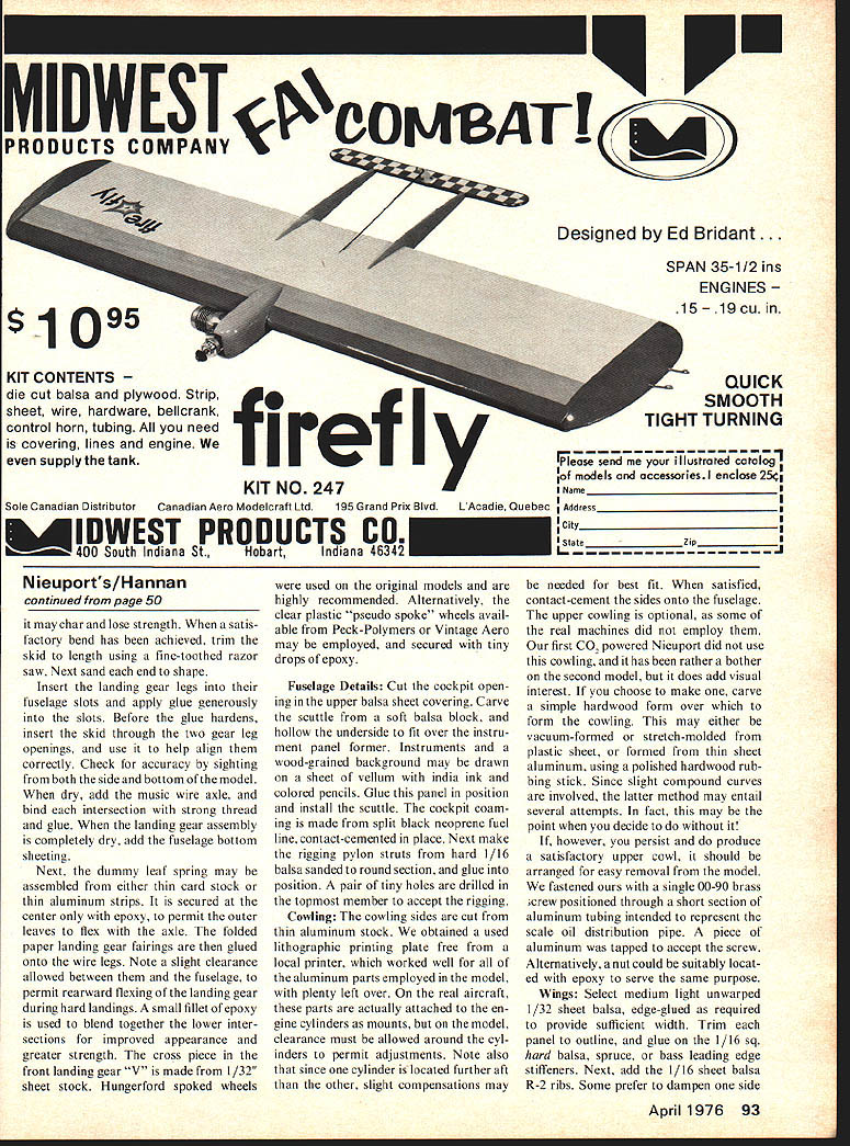
Fuselage Details: Cut the cockpit opening in the upper balsa sheet covering. Carve the scuttle from a soft balsa block, and hollow the underside to fit over the instrument panel former. Instruments and a wood-grained background may be drawn on a sheet of vellum with India ink and colored pencils. Glue this panel in position and install the scuttle. The cockpit coaming is made from split black neoprene fuel line, contact-cemented in place. Next make the rigging pylon struts from hard 1/16" balsa sanded to round sections, and glue into position. A pair of tiny holes are drilled in the topmost member to accept the rigging.
Cowling: The cowling sides are cut from thin aluminum stock. We obtained an electrographic printing plate free from the local printer, which worked well for all of the aluminum parts employed in the model, with plenty left over. On the real aircraft, these parts are actually attached to the engine cylinders as mounts, but on the model, clearance must be allowed around the cylinders to permit adjustments. Note also that since one cylinder is located further aft than the other, slight compensations may be needed for best fit. When satisfied, contact-cement the sides onto the fuselage. The upper cowling is optional, as some of the real machines did not employ them. Our first CO2-powered Nieuport did not use this cowling, and it has been rather a bother on the second model, but it does add visual interest. If you choose to make one, carve a simple headrest/form over which to form the cowling. This may either be vacuum-formed or stretch-molded from plastic sheet, or formed from thin sheet aluminum, using a polished hardwood rubbing stick. Since slight compound curves are involved, the latter method may entail several attempts. In fact, this may be the point when you decide to do without it!
If, however, you persist and do produce a satisfactory upper cowl, it should be arranged for easy removal from the model. We fastened ours with a single 90-oz brass screw positioned through a short section of aluminum tubing intended to represent the scale oil distribution pipe. A piece of aluminum was tapped to accept the screw. Alternatively, a nut could be suitably located with epoxy to serve the same purpose.
Wings: Select medium-light, unwarped 1/32" sheet balsa, edge-glued as required to provide sufficient width. Trim each panel to outline, and glue on the 1/16" square hard or spruce leading edge stiffeners. Next, add the 1/16" sheet R-2 ribs. Some prefer to dampen one side to obtain the required dihedral without hinging the ribs. This method is quicker but requires care. The method shown here uses the dihedral built into the panels, with 1/2" rise at each tip. Build the wing panels on a flat board, using the plan and spars to establish rib spacing. Fit the center section and join the panels, taking care to align the trailing edges. When dry, sand the wing to shape and add the 1/32" sheet center-section fairing. of the wing panel to create an automatic camber, but ours were simply curved dry, and the ribs were held in place with masking tape while drying. Contact cement represents another possible approach. Sandpaper all surfaces smooth, and round off the edges.
The lines representing the real aircraft wing rib locations are drawn on with a fine-tipped fiber-point pen or ball-point pen. We prefer brown ink, as it provides a more subtle effect than black. A couple of sprayed-on coats of clear will protect the lines from moisture. Caution: Try first on a scrap, as some coatings will attack the ink and cause "bleeding" of the lines. Clear enamels, such as used on plastic models, seem not to affect any inks we have tried, whereas clear dope may.
Tailplanes: Select light, flat 1/32" balsa stock for the tailplanes, and cut to outline, noting the grain direction in each part. Assemble the stabilizer/elevator parts, and add the very hard 1/16" square anti-warp strips to the underside. Sand all edges smooth, and draw on the rib and control separation lines.
Decor: Before final assembly, attend to the detail finishing, which contributes a great deal toward alleviating that stark, plain balsa look. The cowl sides, top, bottom, and firewall are all natural aluminum color, as is the scuttle. The landing gear assembly should be painted flat medium gray, as should the warp control rod. The dummy leaf-spring may be painted Pactra "steel" color for a realistic appearance.
Most of the real machines seem to have been covered in natural fabric, which was probably a slightly off-white when new, but which gradually aged to a buff color, not unlike the color of balsa. The aircraft in the Musee de l'Air features a tri-color rudder as indicated on the plans.
At least a few Nieuports featured carmine-colored fuselages and rudders, and we simulated this scheme by covering those components with colored tissue. Some of the machines featured the manufacturer's name in bold letters on the fuselage sides, while still others bore racing numbers on the fuselage or rudder sides. Supposedly, a few of these machines served as trainers and scouts during the early stages of World War I and may have sported cockades, but to date we have only seen photographic evidence of the Gnome rotary engine versions so marked.
If you are using a horizontally mounted single-cylinder CO2 engine, a Williams Brothers 1/2" scale dummy cylinder will simulate the second cylinder very realistically. For flying purposes, a Williams Brothers nylon prop trimmed to 4-1/4" diameter will serve. These may be dyed brown using regular clothing dye in hot water, for better appearance.
Assembly: Install the wings. Probably a small amount of trimming will be required to obtain a good fit at the center juncture, and to clear the aluminum side cowl. Cover the wing center joint with a strip of tissue or silk for added strength. Check carefully that the dihedral angle is correct. Add the hard 1/16" sheet balsa R-1 ribs to additionally reinforce the wing/fuselage joints.
Add the fairings, being certain that they are correctly aligned. Cement the warp control rod and its aluminum control arm in position. Note that the rod is not glued at the top, and is free to slide back and forth in the rod housing. This allows movement, as in hard landings. Incidentally, the warp control rod in the real machine was actuated by the pilot's feet, while the rudder was operated by sideways movement of the control stick.
Install the silk thread rigging, which, with planning, may be done in one continuous length. A sewing needle may be used to pass the thread through the wing panels outside the R-2 ribs. This rigging pattern corresponds to the strength of the model, and should not be omitted. Also, minor warps may be corrected by means of the rigging. Simply use a drop of glue to fix the rigging to the wing while holding it in the desired position. Silk thread is very strong and free of the unrealistic "fuzz" found in more common sewing thread. Nylon thread is unsuitable, as it sags excessively with temperature and moisture changes, as your author learned the hard way!
We suggest adding a dummy pilot (or even a smart one!) to avoid that empty cockpit look. Our "Lucky Pierre" was carved from soft balsa and painted with matte colors.
Flying: Your model should balance close to the point indicated on the plans, and may possibly require ballast to achieve this. Recheck model for freedom from warps. It is particularly important that there not be even a hint of down elevator, or your Nieuport may exhibit ballistic tendencies! A shade of up elevator is relatively harmless, but may bring about the need for additional nose ballast. Testing should be performed on a windless day, as the model is sensitive to gusts. If possible, test over grass, but avoid weeds which may become entangled in the wing rigging. Usually any stalling or diving tendencies can be corrected with ballast, and elevator bending is discouraged. If model persists in falling off on one wing the addition of clay ballast to the opposite wing tip may effect a cure. When the glide appears reasonable set the engine for low speed and charge with fuel. Hand launch, being certain the engine is running in the proper direction, and observe flight path carefully. If model stalls, add a thin shim for slight side thrust to tighten the turn circle. Rudder adjustments should be approached with caution, as in spite of its small area, it can be powerful in action.
We did not need downthrust on either of our models, and in fact one required a tad of upthrust. With power increases, readjustments may be needed. We prefer to fly our models slowly and realistically rather than rapidly. This also reduces the risk of high-altitude thermal flyaways, easily possible with such a light craft!
CO2 Engines: A few words regarding the care and feeding of these powerplants will be appropriate here. These units offer many advantages, since they are very light in weight, quiet in operation, offer no fire hazard, and require no batteries or model fuel-proofing. Yet, like any other form of power, they do have certain limitations, and should be treated with care and understanding.
First, the capsules used to charge the fuel tanks vary widely in quality. Even in a given box, we have found surprising differences in power output. Temperature differences can also affect engine operation, and typically they are handicapped in cold weather. Conversely, an increase in air temperature can increase power output significantly, and it is well to consider this before launching a model previously adjusted in lower temperatures. For example, our Nieuport, set for very docile flight in San Diego, climbed wildly in the elevated temperatures found at Taft, Calif.
Engine speed adjustments, made by rotating the cylinder(s), should be very slight to avoid damage. We prefer to do this with the engine running. Don't forget to oil your engine occasionally. Remember that it does not receive lubrication from its fuel, as do glow engines. Make every effort to keep it clean, and avoid operation in sandy areas. It is made with watch-like precision and deserves the best of care. With proper attention it should last for years.
Sidelight: Although the author has constructed several different variations of Nieuport models over the years, and thought he knew all their idiosyncrasies, he was forcefully reminded otherwise, during the recent Flightmaster Annual Scale Contest. Although one fully-tested Nieuport was available, it was rather old and decrepit looking. The brand-new model shown in our photos was entered instead, in virtually untested condition. On the morning of the event, a heavy fog had settled, which resulted in three unfortunate effects. First, the power output of the engine was reduced; second, the nylon rigging went slack in the moisture-laden air; and third, the model flew backward in an updraft and was lost.
Nieuport's (continued)
reducing wing rigidity; and third, the elevators took on a slight but decidedly negative warp. Probably had the model been left alone for a few hours until the fog lifted and the sun appeared, all three problems would have corrected themselves. However, a fog had also evidently settled over the author's brain, and in the resulting comedy-of-errors, the model was repeatedly crashed. It is a testimony to the easy repairability of a sheet balsa model that when the difficulties were finally identified and corrected, the model was flown to second place in its category. The lesson is, of course, an old one, but a humbling reminder: Think before you fly.
Acknowledgments: Special thanks for assistance are extended to the following: D. J. Gillies, Bill Warner, John Underwood, Georges Chaulet, Jim Leukeb and all the Flightmasters.
Supply Sources: Hungerford wheels: FH Wheels, 1770 Lilac Circle, Titusville, Fla. 32780; Peck-Polymers, Box 2498, La Mesa, CA 92041; Vintage Aero, 1 The Glen, Tenafly, N.J. 07670.
Clear "pseudo-spoke" wheels: Peck-Polymers, Vintage Aero.
Crockett Co. engine mount rings: Peck-Polymers, Jim Crockett, 1442 N. Fruit Ave., Fresno, Ca. 93728.
Transcribed from original scans by AI. Minor OCR errors may remain.

